To avoid these ads, REGISTER NOW!

50" press brake build

Dwerden

Well-known member
Joined
Dec 28, 2018
Messages
130
Location
Ontario
Things are about to get real. I have been stockpiling parts for a few years and finally almost have all of the necessary goods. This will be a single cylinder design with a mechanical linkage for advantage.

These 4x8's will be the uprights, got these for free.99 from a buddy


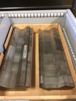
Scored this half inch plate from the scrap yard for $45. This will be used for the punch, arms and links. I willthicken with 1/4 plate on either side for a total of 1" thick


Score on the hydraulic pump and resevoir unfortunetely the motor is 3 phase so will either scrounge another motor or get a vfd. This will probably be the last thing ill worry about and run the ram off of my tractor for now


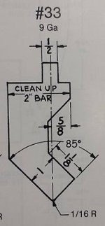
This is the basic design im going with


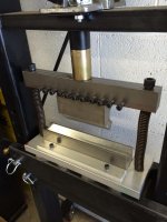
Started on some of the pins and sleeves for the arms

 
Last edited:
To avoid these ads, REGISTER NOW!
OP
D

Dwerden

Well-known member
Joined
Dec 28, 2018
Messages
130
Location
Ontario
Looking forward to see the build progress. How many tons do you thick this will produce?

In the mean time I will utilize a 2.5" ram I have, if run off of my tractor @ 1850psi that only works out to about 10 ton. Perfect for a stainless steel maple syrup pan i need to finish ASAP. Eventually a 4 inch ram will go in its place and if i get a proper power pack sorted out @2500 psi will be about 45 ton. I would like to keep it safe at about 30 and my main goal is to bend 4 feet of 10 ga. so I should be fine at that level. A buddy of mine at the machine shop I used to work at is machining a punch for me this week which I will eventually cut up and make into fingers
 

dr_clyde

Well-known member
Joined
Jan 7, 2009
Messages
6,432
Location
Holland, MI
I think it's a neat idea, but I'm not so sure of the geometry on the ram.

You want your hydraulics more or less on the same axis as your ram. You lose leverage and therefore tonnage when you go on angles that perpendicular.

Look at regular commercial press brakes. The cylinders are pressing up, and the ram is positioned around an axle pressing opposite. Think teeter-totter. This allows a very linear transmission of force.

I think you're really going to struggle to bend 4 feet of 10ga. Unless you're planning to air bend everything, you're gonna need a lot more tonnage to coin 10ga. I know the 60 ton Accurpress has trouble with 4 feet of 11ga, but that's a coined bend. Meaning bottomed in the die.

I bend a LOT of sheet metal on some pretty big brakes. I've never seen a linkage configuration like what you have. Hopefully it works well for you.

Good luck, I'll be following along with interest.
 

Bodj Built

Well-known member
Joined
Feb 3, 2016
Messages
1,165
Location
Moorpark, CA
Additionally, with the configuration you have, your die will shift to the right slightly as it moves down, dragging the piece along with it or scoring it. The added friction probably won't help the compressive forces.
 
OP
D

Dwerden

Well-known member
Joined
Dec 28, 2018
Messages
130
Location
Ontario
I think it's a neat idea, but I'm not so sure of the geometry on the ram.

You want your hydraulics more or less on the same axis as your ram. You lose leverage and therefore tonnage when you go on angles that perpendicular.

Look at regular commercial press brakes. The cylinders are pressing up, and the ram is positioned around an axle pressing opposite. Think teeter-totter. This allows a very linear transmission of force.

I think you're really going to struggle to bend 4 feet of 10ga. Unless you're planning to air bend everything, you're gonna need a lot more tonnage to coin 10ga. I know the 60 ton Accurpress has trouble with 4 feet of 11ga, but that's a coined bend. Meaning bottomed in the die.

I bend a LOT of sheet metal on some pretty big brakes. I've never seen a linkage configuration like what you have. Hopefully it works well for you.

Good luck, I'll be following along with interest.


There are quite a few do it yourselfer brakes built in this fashion online. They seam to be the way to go because they only require one cylinder and no fancy proportioning valves to keep everything in sync $$$. I will just be doing air bends and mostly on 18 ga. SS.
 
OP
D

Dwerden

Well-known member
Joined
Dec 28, 2018
Messages
130
Location
Ontario
Additionally, with the configuration you have, your die will shift to the right slightly as it moves down, dragging the piece along with it or scoring it. The added friction probably won't help the compressive forces.

There are 4" links on the bottom of the arms hard to tell in the 2d drawing but the punch should stay reletively level through the cycle. Having said that I essentially have no idea but these are all semi educated guesses
 

vpd66

Well-known member
Joined
Mar 1, 2010
Messages
709
Location
Central Wisconsin
Looks like a cool project. Why not make it accept commercial tooling? I see brake press tooling come up for sale all the time.
 

dr_clyde

Well-known member
Joined
Jan 7, 2009
Messages
6,432
Location
Holland, MI
Whats your plan for the ways on the ram? You will want some way to allow the ram to slide freely up and down, and have minimal backlash.
 
OP
D

Dwerden

Well-known member
Joined
Dec 28, 2018
Messages
130
Location
Ontario
Little bit of a design change this morning, I decided I wanted to mount the ram above the arms and keep it within the uprights


After that I picked up a ram, wanted to make sure the arms would work and needed to know the dimensions of the clevis end


Once I was happy I started burning out the plates. I'm committed now


This is the sandwiching that will hopefully prevent the entire thing from folding in half


matt_i

Well-known member
Joined
Mar 14, 2008
Messages
10,725
Location
SE Michigan
Additionally, with the configuration you have, your die will shift to the right slightly as it moves down, dragging the piece along with it or scoring it. The added friction probably won't help the compressive forces.

I had the same thought, that while the linkage shown forces parallel operation of the moving die, it also will side-load. You could get away with cam rollers which is a heavy duty rolling element, but those need a hard surface track to run inside.
 
OP
D

Dwerden

Well-known member
Joined
Dec 28, 2018
Messages
130
Location
Ontario
Looks like a cool project. Why not make it accept commercial tooling? I see brake press tooling come up for sale all the time.


The punch that my buddy is making is a standard 1/2" toungue style. The print i gave him is cross section I got from a press brake site .
 
OP
D

Dwerden

Well-known member
Joined
Dec 28, 2018
Messages
130
Location
Ontario
I had the same thought, that while the linkage shown forces parallel operation of the moving die, it also will side-load. You could get away with cam rollers which is a heavy duty rolling element, but those need a hard surface track to run inside.

Most of the brakes I have seen like this just have angle iron bolted to the uprights on either side of the punch to keep it vertical, I was considering using roller bearings but that will depend on how straight everything welds up. I dont see it wanting to push over once it is in contact with the material but I have been wrong before
 
To avoid these ads, REGISTER NOW!

f150skidoo

Well-known member
Joined
Dec 29, 2012
Messages
1,206
Location
Ontario, Canada
In the mean time I will utilize a 2.5" ram I have, if run off of my tractor @ 1850psi that only works out to about 10 ton. Perfect for a stainless steel maple syrup pan i need to finish ASAP. Eventually a 4 inch ram will go in its place and if i get a proper power pack sorted out @2500 psi will be about 45 ton. I would like to keep it safe at about 30 and my main goal is to bend 4 feet of 10 ga. so I should be fine at that level. A buddy of mine at the machine shop I used to work at is machining a punch for me this week which I will eventually cut up and make into fingers

These designs of press brakes due to the lever actually multiply the force. I would guess by your pics your brake would be 2.5 or 3:1 mechanical advantage.
 
OP
D

Dwerden

Well-known member
Joined
Dec 28, 2018
Messages
130
Location
Ontario
These designs of press brakes due to the lever actually multiply the force. I would guess by your pics your brake would be 2.5 or 3:1 mechanical advantage.

Yes, 2.3:1 to be exact, the ram I just bought is 31400lbs @ 2500psi x 2.3 = 72200lbs. So 36 tons. If I use my tractor @ 1850 psi it is about 25 ton. If that will meet my goals i will keep it at that level and hopefully It will last a lifetime without self destructing.

The ram I had wouldnt work once I changed the arm to stay inside the uprights, I needed more travel
 
OP
D

Dwerden

Well-known member
Joined
Dec 28, 2018
Messages
130
Location
Ontario
How will you control the stroke of the punch?


Not 100% sure yet. If it is slow enough that i can repeat on a digital readout i will probably make due with that. I also have a 120v solenoid that could be actuated by a limit switch.

If my math is correct the punch will be travelling 1 inch in 5 seconds. If i do a test bend, get 90 degrees and 0 the readout Im hoping it is slow enough that I can repeat that zero on the next piece . I am not a press brake opperator but that seems to make sense and it is simple if it works
 

Fix Until Broke

Well-known member
Joined
Feb 21, 2016
Messages
794
Location
SE Wisconsin
The cylinder to the 1st set of arms has a ~2.3:1 ratio (when things are perpendicular), but the linkage between the 1st set of arms and the little dogbones gets progressively higher as the cylinder extends.

Think of a vicegrip - this works the same way, but (hopefully :)) does not go over center. You're 33 tons is at first engagement with everything more/less perpendicular, it will be way more than that as the cylinder extends and the three lower pivot points get closer and closer to a straight line.

This gives you two advantages - Much higher force at the end of the bend, and also much lower motion ratio at the end of the bend. So the cylinder will move 2.3" and the dies will move 1" at the beginning of the stroke, but at the end of the stroke it might be 2.3" for the cylinder and 0.1" for the dies (for example).
 
OP
D

Dwerden

Well-known member
Joined
Dec 28, 2018
Messages
130
Location
Ontario
I cut a chunk of 6x6 square tube this morning and started laying it out for my pins. I cut these templates so I could hand cut some half decent holes


Then I turned it over and cut some square holes. The inside plates fit pretty good, 2 joints had about an 1/8 gap but nothing a little 6010 couldnt fix


Then i slid in my pin with the collars on it and tacked everything


Then lots of velding


This is where im at, good accomplishment for the day. Tommorow I need to machine some more pins and sleeves for the links and tie rod


mrolds88

Well-known member
Joined
Feb 17, 2010
Messages
117
Location
WV
At 31400lbs pressure (push) how is that 4x8 tubing going to act? I would think that there is going to be a fair amount of flex with a simple upright, as I see in your drawings.
 
OP
D

Dwerden

Well-known member
Joined
Dec 28, 2018
Messages
130
Location
Ontario
At 31400lbs pressure (push) how is that 4x8 tubing going to act? I would think that there is going to be a fair amount of flex with a simple upright, as I see in your drawings.


You're not wrong.. I have a few different ideas of how im going to brace that one.
 
OP
D

Dwerden

Well-known member
Joined
Dec 28, 2018
Messages
130
Location
Ontario
Lots more pins and sleeves machined yesterday


Got em all tacked in, one pass of weld on the sleeves then put the 1/4 plate on and welded everything up.


Then I cut out the clevis ends for the connecting/tie rod


Just got done machining the last of the sleeves, have one more little shaft to turn then I should have everything to get this linkage done and after that its a walk in the park. Just trying to figure out how to build it so I can stand it up afterwwards because shes gettin' heavy
 
Last edited:

jeepinerdeep

Well-known member
Joined
Dec 28, 2013
Messages
2,099
Location
South Central PA
Love it all, but hope you'll consider a chunk of commercial gooseneck punch.

I am sure glad I did.
 

Attachments

  • $_10.jpg
    $_10.jpg
    12.7 KB · Views: 144
  • IMG_0655.JPG
    IMG_0655.JPG
    98.3 KB · Views: 185
  • IMG_0748.jpg
    IMG_0748.jpg
    96 KB · Views: 192

bullnerd

Well-known member
Joined
Sep 17, 2012
Messages
5,690
Location
Jersey
How will you control the stroke of the punch?

If you seriously want to control this thing, get in touch with JGSFAB, Instagram would probably be the easiest. Tell him Bullnerd sent you. Super nice guy and crazy talented with cnc/control ideas on a budget. He designed the tube pro (bend techs Dragon) in his garage with basically scraps.

Actually I think he just cnc'd a huge press brake, its on his IG.
 
OP
D

Dwerden

Well-known member
Joined
Dec 28, 2018
Messages
130
Location
Ontario
Love it all, but hope you'll consider a chunk of commercial gooseneck punch.

I am sure glad I did.

Would be nice but 50 inches of that is likely worth more than the whole press haha. If this thing works as it should and doesnt self destruct I will probably invest in a proper 4 way die.. maybe
 
OP
D

Dwerden

Well-known member
Joined
Dec 28, 2018
Messages
130
Location
Ontario
If you seriously want to control this thing, get in touch with JGSFAB, Instagram would probably be the easiest. Tell him Bullnerd sent you. Super nice guy and crazy talented with cnc/control ideas on a budget. He designed the tube pro (bend techs Dragon) in his garage with basically scraps.

Actually I think he just cnc'd a huge press brake, its on his IG.


Thanks I checked out his page. Maybe somewhere down the line but for now it will be old school lever and protractor
 

bullnerd

Well-known member
Joined
Sep 17, 2012
Messages
5,690
Location
Jersey
Sounds good, just wanted to mention it.

Looks good so far.

What plasma table are you using?
 
OP
D

Dwerden

Well-known member
Joined
Dec 28, 2018
Messages
130
Location
Ontario
Sounds good, just wanted to mention it.

Looks good so far.

What plasma table are you using?

Im always open to suggestions as I'm just winging it. The table is a "plasmatech" a guy a couple hours from me that builds them. It has been pretty good, I couldnt even imagine building this without it. Definetely a huge time saver

 
OP
D

Dwerden

Well-known member
Joined
Dec 28, 2018
Messages
130
Location
Ontario
Only a bit of progress today on the brake, wifey wanted to go do some work on the sugar shack this morning so I got my new stainless chimney installed


Back to the brake, got the clevis ends welded up with the sleeves and tacked the tie rod in place. Hopefully it drops level and doesnt need an adjustment like I see in most of these, I match the center to center distance of the pivot point so it should be pretty close, if not i have a plan B
 
OP
D

Dwerden

Well-known member
Joined
Dec 28, 2018
Messages
130
Location
Ontario
I've also decided to trade my 12" ram in for a 14" which should give me almost 6" of stroke.
 
Last edited:
To avoid these ads, REGISTER NOW!
Top Bottom