You are using an out of date browser. It may not display this or other websites correctly.
You should upgrade or use an alternative browser.
You should upgrade or use an alternative browser.
66 F100 Rustomod
- Thread starter Ohmthis
- Start date
I’ve done two other projects (race vehicles though) and definitely learned the good and bad. I’ve built this truck in my head dozens of times looking for potential issues. This is my only area to work on vehicles and I can’t afford to have a stranded project waiting on me to get my **** together. I appreciate you following along.You only do it because NOT doing it has cost you time and money before in the past.
Ask me how I know.
Quick update. I had a bit of free time to play in the shop. My engine was in the basement and it was a bit of a job to get it upstairs to my shack shop. My so. Drove the truck around and helped me load it up. Once we got it up I connected the transmission and had help from my son changing the oil pan (required to get the sump behind the cross member). We sat it in place and realized that the factory transmission mount cross member is definitely in the way. That’s as far as I had time for. Thanks for looking!
Attachments


emeraldcoupe
Well-known member
i don't know how it compares, but when i put the 4r70w in my 71 i had to move the trans x member back about a half inch
It looks like I’ll have to move it a quite a bit. The mount studs on the transmission are about 1/2-3/4” away and the whole drivetrain needs to move back 5-6” or maybe more.i don't know how it compares, but when i put the 4r70w in my 71 i had to move the trans x member back about a half inch
You are absolutely correct. I played a little with it last night. Nothing I did was picture worthy. I need to trim the floor to get the transmission up into the cab. Hopefully I can get to that today.The trans tunnel is shallow on the 2wd trucks as well. BUt you would think still enough room.

Transmission Floor Cover Plate - 1965-72 Ford Truck | Dennis Carpenter Ford Restorations
Transmission Floor Cover Plate - 1965-72 Ford Truck 1965 1966 1967 1968 1969 1970 1971 1972 F100 F250 F350 C5TZ8112110A
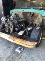
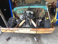
Oh my!!! It seems like I’ve been tweaking the placement of the drivetrain for days…….not really, but damn. I’ve got some progress to report. After dozens of in and outs of the drivetrain, moving crossmembers, and cutting the floor I’ve got the engine and transmission resting in place. I now need to come up with an idea for motor mounts and modify the transmission crossmember. Here it is before final placement. I was looking to make sure there is room around the engine for exhaust, the starter, and see where the fuel and return lines can route.
Attachments


After liking what I saw i finagled the drivetrain in a very basic place and started measuring. The factory setup is skewed the the passenger side, but I mocked it up centered in the frame. I then laid on the floor (WTF, I have a lift. I’m not supposed to laying on the dirty floor!) and marked where the shifter would penetrate the floor. With the whole setup out of the way I cut the floor. I made a smallish cut first and then lined things up again. Here is a picture of the cut.
Attachments

After more wrestling with a 5.0 HO and the transmission I got things centered and lined up level side to side. Ive got the transmission up between the frame and resting on the factory crossmember for now. There is plenty of room around the transmission so no knocking or banging . Sorry for the ****** pictures, the garage door was open and glare from outside.
Attachments
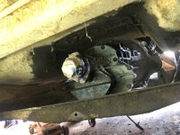
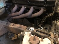
And finally resting in place with the intake on. Here are pictures of the motor mount areas. The factory CV are the squares on the subframe. The studs pointed downwards are the engine mounts. Id like to come up with something to connect the two. I want something that looks nice and is also strong. I’ve got a few ideas and I’ll cut some things in CAD (Cardboard Aided Design) and see what I can make that’s not too complicated, yet works for what’s in my head. If you guys have any suggestions, please let me have them. Thanks for looking!
Attachments


Getting that truck back on the road is what it is all about. Just think our trucks were used and abused for all those years and now have new life and will survive maybe even longer than us instead of being recycled.Thank You! I appreciate the help that you’ve given me. I’m hoping I can repay you someday.
I love taking things that are “Junk” to other people and making them new(ish) again. Plus, it’s a cool legacy to look at it later and say “I built that”.Getting that truck back on the road is what it is all about. Just think our trucks were used and abused for all those years and now have new life and will survive maybe even longer than us instead of being recycled.

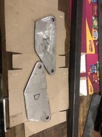
I measured kinda what I needed and sketched a few designs for the plate that mounts to the block. Once I found one that cleared everything and was wide enough to mount to. I drew it out on cardboard and checked it out. Here are my cardboard templates and it copied on plate. I used a bandsaw and cutoff wheel to cut out the plate and filled the holes.
Attachments


I wanted the box pieces to have shape versus just be strong. I cut the side that mounts to the subframe on a 45, partly to slide the mount bolt in and have access to weld it and partly to have it not so blocky. I plan to weld a piece of plate over the opening and blend the welds to finish the look.
Attachments

I really want to put some type of vibration control into the mount. The vertical piece of box tube might be temporary. I’m going to looks for a rubber isolation piece with studs on both sides. This being solid mount might shake my teeth out. Here it is all tacked together that’s the way it will stay until either I find something suitable or I just get impatient.
Attachments


rattle_snake
Well-known member
Given this is GJ, I suggest you get a CNC plasma...
Truck is really coming along quickly. Impressed.
Truck is really coming along quickly. Impressed.
Justin, I wish I had the room for one. What really ***** is that I have all kinds of cool useful tools. Too bad they are spread between 4 places. 3 are at least at my house, but a lot of my fab tools (2 drill presses, horizonta/vertical bandsaw, belt/disc sander, notching tool, and my 80 gal 2 stage compressor) are at my dad’s place. I am getting by and making pretty good headway. Thanks for looking and I appreciate the kind comments. I’ve taken some ideas from your truck and will be using them when I progress.Given this is GJ, I suggest you get a CNC plasma...
Truck is really coming along quickly. Impressed.
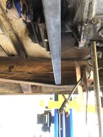
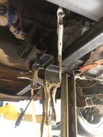
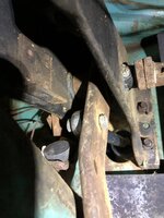
it’s been a little while since I last posted. Between a weekend being sick and activities for my older kids I got “play” some today. Not much really, but progress none the less. I fabbed up the transmission cross member. I measured between the frame rails and cut a 1.25 square tube. I placed it between the rails and held a piece of angle iron that the transmission pad will bolt to. After checking the angle of the transmission (3-5* was what I was shooting for) I marked all of the centers and clamped together. I didn’t have any exhaust pipe, but I did have a piece of 2.5” PVC conduit. I used it to mock up the exhaust pipe. I wanted to make sure I had room.
Attachments


Last edited:
I wanted to tig this bracket together only because I haven’t used my tig in almost 2 years. I got it tacked and then ran a couple of beads. In my small shop it’s hard to get the welding cart over to my work bench with something in the bay. I stood next to the cart and welded. I know I definitely need some practice, but I couldn’t even rest my torch hand. All in all it will do.
Attachments


Next up was to drill the holes for the mounting studs. I took a pair of digital calipers and measured the center to center of the studs. Then the diameter was measured. I split the center to center in half and scribed off of the center of the mount. Once both marks were scribed, I measured them to make sure my math or layout was correct. I center punched them and drilled the out.
Attachments


Boltsandnuts.com has great selection on hardware. I bought a small SAE set a few months back for my F100. Using old beatup bolts drives me nuts. No pun intended.I still need to drill the frame and bolt it all down. I need to get some hardware first. Thanks for looking.
")
I’ll need a bunch of hardware to put the front sheet metal back on. Would you recommend them or one of the restoration companies? I usually just hit ACE down the road for a few fasteners here or there. Besides them being most specialty, buying in bulk should save me some money. Thanks for looking.Boltsandnuts.com has great selection on hardware. I bought a small SAE set a few months back for my F100. Using old beatup bolts drives me nuts. No pun intended.
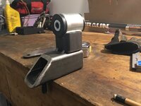
I’ve been kinda lazy with getting things posted. I’ve been working and taking some pictures. I have been looking for the mount I wanted to complete my motor mount. Well, I got tired and went a different way. I bough A kit that has a 2” piece of DOM, bushings, and the sleev to mount it. I bought two of them. I cut the riser section short and notched it for the DOM.
Attachments


Now that the drivetrain is permanently mounted, I can move forward. I pulled the engine and transmission to clean them and paint things. The firewall and frame was crusty, greasy, and just nasty from years of oil leaks and rod grime. I dosed it down with super clean and pressure washed it. I hit the inside of the cab as well. It took several attempts, but it’s much better. So now I’ve got a date with a wire wheel and some paint.I can’t decide to paint the firewall satin black (same as the inner fenders and core support) or the original color. What say you guys? My engine will either be black with silver valve covers and intake, or ford blue withe the silver valve covers and intake. Any other ideas? Thanks for looking!
Attachments
-
 B9FD1D70-26B9-401A-9451-4CF2003E43C1.jpeg931.4 KB · Views: 31
 -
 836304BC-8B9E-4C8A-BC2A-F71AB2564A18.jpeg790.2 KB · Views: 30
 -
 0DD9E900-629D-43D4-B519-D63CFE2D07E0.jpeg693.1 KB · Views: 27
 -
 7914C6FD-1CCE-4022-8D36-AAA6DF886B49.jpeg674.7 KB · Views: 25
 -
 F36EB16C-F639-4AF5-BF65-D85136412CC1.jpeg622.8 KB · Views: 40
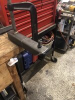
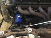
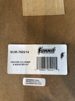
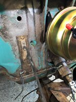
Time for another installment of how the Rustomod turns. Well before I can paint the firewall I need to mount the brake and clutch master cylinders. Lucky for me I found a kit supposedly made for the 57-72 f100. Reviews were mostly positive and I thought what the hell. This kit is from summit and the biggest knock that I saw was that there are no instructions. Im the kinda guy that starts putting things together and then go back to the instructions  . It really was a good kit and was actually easy to install if you’ve been around vehicles and know how they work. Here are the pictures of the brake set up. I’d love to keep the components looking fresh like this. Can anyone suggest a paint or clear that will play nice with brake fluid?
. It really was a good kit and was actually easy to install if you’ve been around vehicles and know how they work. Here are the pictures of the brake set up. I’d love to keep the components looking fresh like this. Can anyone suggest a paint or clear that will play nice with brake fluid?Attachments

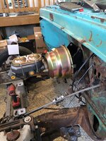
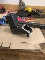
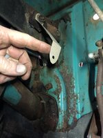
On to the clutch master cylinder. My transmission is from a 95 F150, so naturally I’d use the factory clutch master. I had planned on mounting this on the right side of the brake booster since there is so much room. But, When setting up the brakes I noticed the clutch pedal actuates a rod. I decided to uses that side to actuate the pushrod of the clutch master cylinder. I took the rod off and made a piece of cardboard to mimic the linkage. I marked the firewall and measured the center at full pedal up and down. I needed 2” of stroke to completely push the clutch. I ended up getting 2.5”. I had made a mark with a marker, in my pictures you will see a hole. I had committed by that point.
Attachments

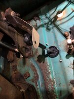
I used my knock out set to make the hole for the master cylinder access. I then double and triple checked my measurements. You can see that once the master cylinder is installed how the linkage will line up. The last two show how much stroke I’ll have.
Attachments
-
 514A6ADF-A345-4ADB-8E5A-E1B9F3A56F81.jpeg697.3 KB · Views: 25
 -
 273CA84C-27D9-40D7-BD30-77CFA4E25A47.jpeg697.3 KB · Views: 24
 -
 547A1025-082C-4FE7-874B-B45F974CCDF4.jpeg734.8 KB · Views: 22
 -
 B073CBA2-599B-4746-BC4E-645D9E7F9107.jpeg859.3 KB · Views: 21
 -
 703F9033-3A57-4DAE-8AD0-AAAF05B04107.jpeg815.2 KB · Views: 21
 -
 E658CE27-2EF1-4740-B7F2-C1205B20F912.jpeg893.5 KB · Views: 23
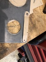
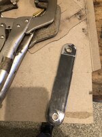
I transferred the cardboard to metal. I used a socket to mark the round ends and center punched the bolt hole. I cut it out of 1/4” plate and cleaned things up with a sanding disc. I don’t have anything that will bend 1/4” so I marked where the bends are from my template. I used a cut off wheel to cut about half way and bent the angles I needed.