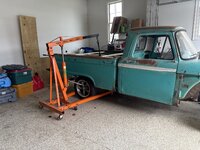
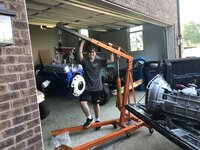
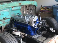
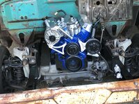
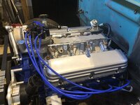
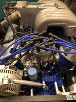
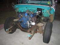
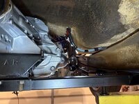
My son and I went to the Street Rod Nationals here in Louisville. We enjoyed the weather and cars. Once I got home I was motivated to get some work done. I’ve been puttering around with small details on the engine and waiting to install the drivetrain permanently. I finished bolting down the lower intakes and got the rest of my driveline parts set up. My son and I got the engine off of its stand and added the pilot bearing, flywheel, clutch disc, and pressure plate. We put a new hydraulic throw out bearing in the transmission and mated them together. He helped me line it all up and gently place them in. There was no cursing or stress. All in all a great day together. Here he is helping me and acting silly (like he’s holding the whole drivetrain). The engine looks great in the frame. Thanks for looking.

You are using an out of date browser. It may not display this or other websites correctly.
You should upgrade or use an alternative browser.
You should upgrade or use an alternative browser.
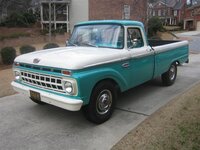
66 F100 Rustomod
- Thread starter Ohmthis
- Start date


WoodsTruck
Well-known member
- Joined
- Jan 12, 2013
- Messages
- 1,029
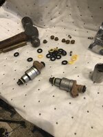
What is your process for the inejectors in the UC?I installed the injectors and fuel rails. I forgot to mention when rebuilding the injectors That they got multiple baths in the ultrasonic cleaner.
Solvent of choice?
Pulsing the injectors while in the bath?
I pull the little filters out. Run the temp up to about 140f (55c on the display). I add 2 capfuls of super clean and set it for 15 minutes. I did three sessions. I did not pulse the injectors.What is your process for the inejectors in the UC?
Solvent of choice?
Pulsing the injectors while in the bath?
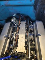
I got to work (play) a little last night. I’ve been working on wire tucking all of the wiring on the engine. I’ve got the alternator wiring and EFI harness tucked up next to the fuel rail. I plan to mount the coil and Map sensor on the firewall. The rest of the wiring will run down the bell housing and enter the cab in front of the shifter. Thanks for looking.
Attachments
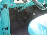
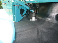
So I stole an hour when I got home from work today. I really wanted to get the mess of wire and believe me, it’s a mess inside the cab. The plan is to build a console for the shifter from the dash to the front of the seat. After looking at where everything was under the dash the most logical place for me was just up from the shifter in the trans tunnel. I used a set of dial calipers to measure the notch of the factory rubber grommet. It’s oval shape to get the computer plug in. 1 1/2”x3” oval was what I needed. I placed a piece of cardboard over the transmission to keep nasty metal shavings out. I marked it on the sheet metal and drilled a couple of pilot holes for a 1 3/8 hole saw (yeah I know it’s not exactly 1 1/2, but they don’t cut that exact either), after drilling my holes I cut the rest with a set of snips. I deburred the hole with a file and proceeded to very carefully stuff this wad of wire in. All in all I call it a success. I will tidy everything up and build the relay box. It all has to come out for paint, but I know it will fit. This also gives me a place for other wiring to pass through for the fuel pump, fuel sending unit, rear lights and similar if I choose to. Thanks for looking!
Attachments


rdoty
ALLIANCE MEMBER
Did you consider installing a bulkhead connector for the wiring?
I actually have one, it’s rated for up to 14 gauge wire and I’ve got a #8 and #10 in there. I also worry about the pins as a failure point. The factory didn’t use a bulkhead connector and the engineers are smarter than me. Thanks for replying.Did you consider installing a bulkhead connector for the wiring?
rdoty
ALLIANCE MEMBER
Makes sense - #10 and #8 can carry a lot of current.
On my '63 Imperial I used two pins on the bulkhead connector in parallel for some of the power circuits. I was comfortable with this for #12. #10 would be pushing it. Forget about it for #8! And in my application everything is fused next to the battery.
As for the engineers being smarter than you, I really doubt that. Let me put it this way - I'm an engineer...
Wiz02
Well-known member
It's not only a question of smarts, but beans. The bean counters are always pushing to reduce costs.Makes sense - #10 and #8 can carry a lot of current.
On my '63 Imperial I used two pins on the bulkhead connector in parallel for some of the power circuits. I was comfortable with this for #12. #10 would be pushing it. Forget about it for #8! And in my application everything is fused next to the battery.
As for the engineers being smarter than you, I really doubt that. Let me put it this way - I'm an engineer...
rdoty
ALLIANCE MEMBER
Tell me about it! One of my great regrets was not taking that Cost Accounting course 30 years sooner. That would have helped _so_ much in dealing with the bean counters!
The #8 is the feed for the relay box I’m building. It will have the relays for the EEC power, O2 sensor power, ignition power, fuel pump, and high/low beams. It’s definitely overkill, but I had it on hand and I won’t have to worry about it. The #10 is the ground for the cab. I’ll be welding a stud to the firewall under the dash and bonding it. I would usually just use a ground strap or wire off of the engine to the firewall, but this fits in to the wire hiding.Makes sense - #10 and #8 can carry a lot of current.
On my '63 Imperial I used two pins on the bulkhead connector in parallel for some of the power circuits. I was comfortable with this for #12. #10 would be pushing it. Forget about it for #8! And in my application everything is fused next to the battery.
As for the engineers being smarter than you, I really doubt that. Let me put it this way - I'm an engineer...
BigMike62
Well-known member
Nice work. I restored a 65 F250 about 10 years ago. My buddy bought it from the original owner around 2009 and only painted the outside. I kept the paint job that was on it but did a semi-frame off from there. I didn't remove the cab but completely re-coated the frame (POR15 and Black enamel). I also did all of the interior. I added power front disc brakes and power steering from a 72 F250. It came from Idaho and was completely rust free.
Attachments


rdoty
ALLIANCE MEMBER
Ahh, yes. I ended up mounting a Bussmann fuse/relay box about 6 inches from the battery and hanging the high power circuits, mainly the headlights, power windows, and power seats directly off of that. Can't remember if I had #6 or #8 going into the fuse/relay box. For that short a run it doesn't really matter.The #8 is the feed for the relay box I’m building. It will have the relays for the EEC power, O2 sensor power, ignition power, fuel pump, and high/low beams. It’s definitely overkill, but I had it on hand and I won’t have to worry about it. The #10 is the ground for the cab. I’ll be welding a stud to the firewall under the dash and bonding it. I would usually just use a ground strap or wire off of the engine to the firewall, but this fits in to the wire hiding.
Great to see you making progress on the build. Looking good!
(Which son gets to drive it first?)
Wow! That’s gorgeous! I want my engine compartment and interior like yours, but leave the outside alone……after a good clean up.Nice work. I restored a 65 F250 about 10 years ago. My buddy bought it from the original owner around 2009 and only painted the outside. I kept the paint job that was on it but did a semi-frame off from there. I didn't remove the cab but completely re-coated the frame (POR15 and Black enamel). I also did all of the interior. I added power front disc brakes and power steering from a 72 F250. It came from Idaho and was completely rust free.
I plan to bring another #8 in for the fuse block. It will split into two #10. One to feed the constant hot side of the fuse block and the other switchEd with a relay to feed the switched side. I don’t like a single #10 feeding the entire fuse block. Nothing crazy will be added, but I want to be prepared. Thanks for the positive comments, this guy to drive it first!Ahh, yes. I ended up mounting a Bussmann fuse/relay box about 6 inches from the battery and hanging the high power circuits, mainly the headlights, power windows, and power seats directly off of that. Can't remember if I had #6 or #8 going into the fuse/relay box. For that short a run it doesn't really matter.
Great to see you making progress on the build. Looking good!
(Which son gets to drive it first?)

I’ve been reading everyone’s posts and I had to get something going. If you live in the Midwest and over to the east coast you understand how cold it’s been. My garage/shop is insulated like a house, but I don’t have any HVAC……Yet. It stays about 30* warmer than outside. We’ve been in the teens for highs going on 2 weeks now. It was warmer today so time to take advantage.
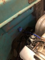
I continued laying out the wiring. I plan to have the battery in the bed with an old keg made to cover it up and give some character. I wanted to make sure the power cable is out of the way of the exhaust. I put my headers on loosely (be nice they will be blasted and painted with Cerakote) and added the collector. This will let me see where things will be and I can avoid them. Here is a picture of the power cables from the alternator (#2), the EEC, the fuse block (both #8), and the alternator sensing wire.
I chose different colors for the two #8 wires so I can’t confuse them. Everything will be covered with a mesh type cover. I’m crimping the fusible link to both #8. I will be using a maxi fuse on the alternator.
Attachments


I bundled them together and used tape as a temporary means until it’s all ready to be done with. I then used Adle clamps and sheet metal screws to secure them. I will be using machine screws and captive nuts for the final product. I also laid the O2 wiring in place and held it there with zip ties.
Attachments

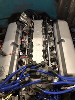
Last thing I did was to add a couple more wires to the engine for things like fan switch, oil pressure and water temp senders, and two spares. I then hung the ignition coil and MAP sensor on the fire wall. This is it for the engine wiring. The rest of the wiring will run up under the inner fenders. Thanks for looking!
Attachments

stinkity stoink
Well-known member
Lookin good !!
what crimper is that on the cables? I keep going back and forth if I should buy one or keep using my hammer type crimped for battery cables.
what crimper is that on the cables? I keep going back and forth if I should buy one or keep using my hammer type crimped for battery cables.
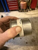
It’s a hydraulic type (import sold under several “names”). I can post up a picture of the label. It’s worked really good for me. I’ve done about 25 or so crimps on wire from #8-4/0. I like that I can use it in any position and don’t have to have room for either longer handles or to swing a hammer.Lookin good !!
what crimper is that on the cables? I keep going back and forth if I should buy one or keep using my hammer type crimped for battery cables.
stinkity stoink
Well-known member
Post a picture when you can please.It’s a hydraulic type (import sold under several “names”). I can post up a picture of the label. It’s worked really good for me. I’ve done about 25 or so crimps on wire from #8-4/0. I like that I can use it in any position and don’t have to have room for either longer handles or to swing a hammer.

WoodsTruck
Well-known member
- Joined
- Jan 12, 2013
- Messages
- 1,029
I've got one like that. Works well for everything I've put through it.Here you go! It’s supposed to crimp cable ends steel(stainless) for hand rails, boat rigging, others.
rdoty
ALLIANCE MEMBER
Making progress! May your electricals be gremlin free!
stinkity stoink
Well-known member
Quick search of that number and found it for $50. Thanks !Here you go! It’s supposed to crimp cable ends steel(stainless) for hand rails, boat rigging, others.


I did a quick mockup before needing to leave for a cheer event (my daughter is in HS Cheer, someone kill me please!). I’m going to trim up the pipes to get it above the transmission crossmember. It will fit a ton better for my plans. Sorry for the dark pictures!
Attachments


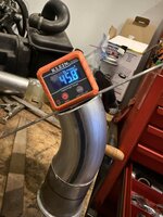
I got out today and started trimming and lining up my exhaust. I used my Klein digital angle finder to get an initial angle. I did a little math (the kind I said I’d never use in HS) and came up with the angle of bend I needed. I marked the pipe and wrapped a heavy piece of paper, lining up the edges.
Attachments


Once cut, and filed I used a grinding disc to bevel both sides. I used a rat tail file to debur the ID. Held it place with witness marks, I placed three tack welds. I slipped the straight pipes to make sure they were lined up evenly. That’s all I have done. I need to order an H pipe and some hanger grommets. Thanks for looking!
Attachments


v8nutz
Well-known member
I love my 12 inch disc sander for exhaust work. Maybe the most used power tool I have, an old Harbor Freight one. I would have bought a better brand if I had know how hard I would use it.
I have belt/disc combo…….but it’s at my dad’s house and pretty useless thereI love my 12 inch disc sander for exhaust work. Maybe the most used power tool I have, an old Harbor Freight one. I would have bought a better brand if I had know how hard I would use it.
 . I agree that they are very useful in fitting the pipes.
I’ve been on a special project at work that requires a lot of overtime. I’ve been super busy and unfortunately I have not had time to “play” on the truck. Spring break is here and I’m at home by myself………So, let’s get on the truck! I’ve really been wanting to get the tank in. I’m running a 1970 mustang tank 18 or 20 gal between the frame rails.
First was to get off the bed. I cut the rusty bolts and it was loose. I made a frame out of 2x4’s and used the engine hoist. It made for a pretty easy one man job.
First was to get off the bed. I cut the rusty bolts and it was loose. I made a frame out of 2x4’s and used the engine hoist. It made for a pretty easy one man job.