To avoid these ads, REGISTER NOW!

air line routing

larry4406

Well-known member
Joined
Jan 27, 2006
Messages
19,062
Location
Northern Virginia
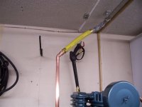
Most of the pictures and guidelines i have seen for air lines show the main line up high on the wall, pitched in the direction of flow, with risers going up from the horizontal pipe then with two elbows to make the down drop with a bleed at the bottom of the run. See the example below.

http://www.tptools.com/statictext/airline-piping-diagram.pdf

Is there anything wrong with inverting this concept? Basically, have the long horizontal pitched run down low (say about knee height), then use a tee to branch up about two feet with a single elbow to turn perpendicular to the wall? Using the diagram mentioned above, the 8 inch riser instead would be about two feet and the point of use tap would be in lieu of the elbow labled "E".

This concept would eliminate a drain valve in every point of use tap, still permits air to be drawn upwards leaving water behind in the main, and the biggest benefit i see is one single drain valve at the end of the horizontal pitched run. This concept also eliminates a number of elbows and connections.

Does any one see any disadvantage to this scheme? I will be installing my airlines next weekend. My airlines will be in the walls (behind drywall) and I do not like the idea of having a bleed on every drop as these bleeds would be under my work bench and possible behind cabinets. So instead of drops, is anything wrong with risers?

I realize i could connect the bottoms of the risers into a common main but this seams to add more complications and expense.

thanks
 
To avoid these ads, REGISTER NOW!

bmwpower

Super Moderator
Staff member
Joined
Apr 24, 2005
Messages
12,578
Location
NJ
The one problem I see with this idea is that you lose the ability to drain the main line back into the tank. The main line should be high and pitched toward the tank. The lower the main line is, the more likely water will find it's way into the main line.
 

Ign

Well-known member
Joined
Jul 7, 2006
Messages
12,769
Location
Butte Peak ND
larry4406 said:
This concept would eliminate a drain valve in every point of use tap, still permits air to be drawn upwards leaving water behind in the main,

The air needs to cool to allow the water to drop out. If you think your plan will allow sufficient cooling, go for it. If not the hot(ter) air will still go throughout your system and drop out at the next lowest point, or whenever it cools.
 

mikeyr

Well-known member
Joined
Sep 16, 2005
Messages
1,971
Location
Santa Barbara, CA
Why drain back into the tank ? I do everything possible to avoid draining back into the tank, tank is way too expensive to replace because it rusted out. I have a drain at the tank and a drain at each drop but rarely (never) get water past the first drop. I think you want your lines sloping away from the tank.
 

z28toz06

Well-known member
Joined
Nov 30, 2005
Messages
1,012
Location
Connecticut
mikeyr said:
Why drain back into the tank ? I do everything possible to avoid draining back into the tank, tank is way too expensive to replace because it rusted out. I have a drain at the tank and a drain at each drop but rarely (never) get water past the first drop. I think you want your lines sloping away from the tank.
The tank has a drain at the bottom. It should be the lowest point in the system. All the water that collects in the system should collect there, not counting water collectors air dryers etc. Open the ball valve for a few seconds daily and let all that condensate out. When air is compressed it heats up, cold air and heat makes condensation. You will get water in the lines, in the tank in the drops, everywhere. The tank is very thick it is the last thing that will rust out, especially if you drain/purge it after each use at the end of the day.
 

MustangRick

Well-known member
Joined
Dec 26, 2006
Messages
308
Location
KC
FNG here...
I plumbed my shop similar to the link that you posted. I did black pipe with 3/4" trunk, 1/2" down legs. I sloped my trunk line down away from the compressor. The main reason I did this is because my compressor is in a back corner of my garage. I walk past my downlegs when I head to the door so then I make sure to purge them often. A key thing that I did that was different then that drawing was to T the compressor into the vertical line with about 2' of pipe below it with the top pipe going to the ceiling. I get more water out of this one then anywhere else.

I have never seen a run that taps off the top, sounds like a good way of doing it as long as you get enough line to get that water to condense before it hits your filter. Before I did black pipe, I did PVC with the downlegs coming off of the bottom of the trunk with a filter right after the compressor. I learned that this kept water in the lines and destroys tools.
 

bmwpower

Super Moderator
Staff member
Joined
Apr 24, 2005
Messages
12,578
Location
NJ
MustangRick said:
FNG here...
I plumbed my shop similar to the link that you posted. I did black pipe with 3/4" trunk, 1/2" down legs. I sloped my trunk line down away from the compressor. The main reason I did this is because my compressor is in a back corner of my garage. I walk past my downlegs when I head to the door so then I make sure to purge them often. A key thing that I did that was different then that drawing was to T the compressor into the vertical line with about 2' of pipe below it with the top pipe going to the ceiling. I get more water out of this one then anywhere else.

I have never seen a run that taps off the top, sounds like a good way of doing it as long as you get enough line to get that water to condense before it hits your filter. Before I did black pipe, I did PVC with the downlegs coming off of the bottom of the trunk with a filter right after the compressor. I learned that this kept water in the lines and destroys tools.

Welcome Rick,
Why would you ever want to direct water towards your drops? You should always pitch the main trunk towards the tank. Get a good electronic drain valve and you never have to remember to drain the tank.
 
Last edited:
OP
L

larry4406

Well-known member
Joined
Jan 27, 2006
Messages
19,062
Location
Northern Virginia
Thanks for the replies, keep them coming.

mustank rick - i will be doing the same tee connection you mentioned at the compressor riser with a 2 foot drip leg and drain valve at the bottom. Thus i will have this riser drain and the compressor tank drain close by. These will be by the exit door to the garage.

My compressor will be located in the front right corner of the garage. From here i will have the riser to the ceiling (12 feet up), go straight to the back wall through the 2x10 ceiling (28 feet back), drop down the back wall (about 10 feet down) then have my main line run the length of the back wall (50) and side wall (28 feet) down low with the riser taps and drain at the end as previously mentioned.

There seems to be debate on whether or not to slope the piping towards the compressor or away. The referenced drawing shows it sloping away and in the direction of flow. For my "up and over" arrangement, I need to make the decision whether or not the 28 foot ceiling front-to-back run should be pitched towards or away from the compressor. With my arrangement, this is the only sloping option i have.

Mustank rick - you used 3/4 black pipe for the mains and 1/2 for the taps. I was thinking on using 1 inch for the mains and 1/2 for the taps. My thoughts on the 1 inch main is i will have about 130 feet of piping and my sand blaster will be tapped off the end. I read somewhere on this forum that if over 100 feet one should use 1 inch. I will be using black pipe as i cannot justify the expense of copper (i know materials choice also has its pro's and cons).

I would like more info on the automatic electric drain valve.
 

mikeyr

Well-known member
Joined
Sep 16, 2005
Messages
1,971
Location
Santa Barbara, CA
I am going to keep suggesting that the slope be away from the tank and with the flow of air, my tank gets enough water in it as-is, it does not need more. Also, the air flow will push the moisture into the line and unless you let all the air out, I doubt that water will drain back into the tank, when I drain my tank, I just crack the valve open for a few very loud seconds, I never de-pressure my system just to drain tank. So we will disagree on that.

A Electric Valve is something I have thought about getting OFTEN, so more info would be great.
 

kbs2244

Well-known member
Joined
Nov 11, 2006
Messages
14,065
I think you will find that most of what they call 'Stndard Insatallition Procedures" are the result of lots of mistakes, and then in the field fixs. Each drop has a drain because the moisture will flow with the air. The slope for the mains will take care moisture that collects when nothing is moving, but start useing a sandblaster, paint gun, etc. and the moisture will not have a chance to collect in the main.
Do it like the drawing. It is the result of a lot of hard learned lessons.
 

z28toz06

Well-known member
Joined
Nov 30, 2005
Messages
1,012
Location
Connecticut
mikeyr said:
I am going to keep suggesting that the slope be away from the tank and with the flow of air, my tank gets enough water in it as-is, it does not need more. Also, the air flow will push the moisture into the line and unless you let all the air out, I doubt that water will drain back into the tank, when I drain my tank, I just crack the valve open for a few very loud seconds, I never de-pressure my system just to drain tank. So we will disagree on that.

A Electric Valve is something I have thought about getting OFTEN, so more info would be great.

Mike, when you are not actively pushing air through the lines, the condensate water will run in which ever direction gravity permits. air has to actually be flowing in the pipes in order for it to push any water towards your tools. If you run the pipes away from the tank water will collect everywhere there is a drop or low spot. If you run it back towards the tank the majority of water will collect in the tank. It sounds like you are under the impression that you have to completely drain the tank to get the water out. This is not the case. Since the water is heavier it will collect at the bottom of the rounded holding tank. Just opening the valve for a few seconds will remove most of the water that has collected there. Not all of it as it will collect anywhere it condensates, which is every where there is ambient air to tank interface. The pipes have very little square footage of this interface compared to your tank, which has many square feet.
 

ron in sc

Well-known member
Joined
Mar 19, 2006
Messages
1,071
Location
Charleston, SC
The system I've used for 5 years has 1/2" galvanized pipe running pretty much level to the other side of the garage where is goes down to the filters and regulator. I've never had any problems, at least that I know of, with water collecting and staying in the pipe. My old system had a teflon and stainless steel hose go from the tank to the ceiling for any vibration.

My new unit has copper 3/4" going up to ceiling with a hose I had made for any vibration which connects to the ceiling. At some point I'll change all pipe to 3/4"
 

Attachments

  • 000_0580.jpg
    000_0580.jpg
    39.2 KB · Views: 309

MustangRick

Well-known member
Joined
Dec 26, 2006
Messages
308
Location
KC
Before I did my real install, I read up as much as I could and everything said to slope away from the compressor. Truthfully, I don't think that part matters as much as making sure the moisture has a place to go.
I had to take my trunk line apart about 6 months after it was installed and there was rust all over the inside of the unions. This makes me think that the best way to do it would be to find the longest length of pipe possible for the horizontal run and slope that towards the compressor. There are some plumbing places that have 20'+ lengths of pipe. I think (think being the key word) that this would be a good way of doing it to get the most moisture out as possible. This also lends some fuel to bmw's argument to slope back.
I do need to correct my self and say that my trunk line does slope back to the compressor the first 20' and the rest (30') slopes away. This probably helps to put so much water in the first down leg. I do not have much water at all in my compressor tank. So little that I tend to not touch it for awhile, an auto drain is definitely high on my list. I also do not get much water in my water seperators at the bottom of the down legs (about 1' up from the ball valves.)
For the trunk line, figure out what your smallest orfice is. My compressor is fairly small 5hp 20g(?) and the built in pressure regulator outlet has an orfice smaller then a pencil lead in it. I could not get my good impact to snug lug nuts. At a buddies shop, it would twist them off. To solve this, I inverted a 70g propane tank and piped that into the line. You could do something similar to this near your sandblaster to add in cfm. But, watch out for compressor over heating issues.
 

mikeyr

Well-known member
Joined
Sep 16, 2005
Messages
1,971
Location
Santa Barbara, CA
at all 3 low spots on my lines, I have a valve to blow out the water so sloping away from the tank works great for me...
 
OP
L

larry4406

Well-known member
Joined
Jan 27, 2006
Messages
19,062
Location
Northern Virginia
It sounds like for my "up and over" arragement then that i should slope as much of the overhead run as possible back to the compressor. This would give me about 40 feet of piping pitched to the compressor before i drop down the back wall and then have no choice but to slope away.

Does the 1 inch pipe for the 130 main seem overkill vs 3/4 inch?
 

Junkman

Well-known member
Joined
Dec 18, 2006
Messages
6,614
Location
Northeastern CT
larry4406 said:
It sounds like for my "up and over" arragement then that i should slope as much of the overhead run as possible back to the compressor. This would give me about 40 feet of piping pitched to the compressor before i drop down the back wall and then have no choice but to slope away.

Does the 1 inch pipe for the 130 main seem overkill vs 3/4 inch?


The rule of pipe is double the diameter and it will carry 4 times the volume. This means that if you go from 3/4" to 1", that you will have doubled the volume of air that the pipe will contain. If you think of the pipe as additional storage capacity, then it is always beneficial to use a larger pipe whenever possible. Every elbow that you add to the system (90 degrees) is like adding 8 additional feet of piping when calculating resistance. Once again, this is a factor that you should consider when you are piping. The more volume of air that can get through the pipe, the better your tools will work. I would use 1" pipe for the main run, and then use 3/4" for the transition tees and elbows, and a 3/4" down pipe. It will cost a little more, but we are all looking for the best performance from out tools, so why make them starve for the air that they need to run at there maximum level?
 

kbs2244

Well-known member
Joined
Nov 11, 2006
Messages
14,065
It does become a question of where the storage is. If it is a tank on the compressor, and you use high volume tools, then you need big pipes to handle the flow. And since the flow in big pipes is slower the water doesn't move as much, so you need slope to the end of the runner with a drain, and a drain at each drop.
Although I have never seen it done, you could go with small pipes and a tank at each drop. That would give you local volume, with small inexpensisve pipes that move the water through them. But then each tank would need a drain since that is where the water would collect.
The most common setup is like your drawing. A pump with a close by tank and drain, to take care of most of the storage and water. The close by tank collects and cools most of the air as it exits the pump. Hoses hooked up directly to top of the tank get cool dry sir.
But, if go to a more fiixed install, and you use high volume tools, then you have to go with large dia pipes to get the flow. So the common way to do it is use 3 or 4 inch as the long distance runners. That gives you increased storage and allows high flow, but it also gives additional cooling. And since the heavy useage does not give the air a chance to stay in the tank and cool down, you get water in the runners. Common pratice is to have the connection come out the top of the tank to avoid as much water in the system as you can, but the virtical going up to the runners will still have a drip leg at the bottom.
To get the needed flow to the tools you go with 3/4 or even 1 inch drops from the runners, but because you now have cooling in the runners, you also need drains for them. The up and over design of the drops in your drawing is to keep as much water out of the drop as possible, but you still need a drain at the low point of the runner as well as on the main tank.
And common practice says a drip leg at the bottom of each drop is cheap insurance. Becouse of cost, these drip legs often do not have a drain, but they do collect water. I have pulled 3/4 inch by 12 inch long drip legs in high volme shops that are full to the top with water and crud after 5 years use.
Like so many things in construction, standard practice seems like it has a lot of make work and unneeded supply useage. But it is the result of a lot of hard earned, and sometimes bad, experiences. The reason most of our homes and buildings work so well for so long is this kind of double and even tripple over building. Does it take longer and cost more up front? Sure. But the pay off is no problems to fix later.
Sorry for the lecture, but it was a lesson I learned the hard way.
 
To avoid these ads, REGISTER NOW!

Bib Overalls

Well-known member
Joined
Dec 4, 2006
Messages
3,318
Location
Jonesboro, Arkansas
I have a second tank plumbed in line with the one that my pump is mounted to (120 gallons total). I have my lines slopped to a dedicated drain and use the up and over routing for my drops. And all my drops have drains. High humidity is common here in Arkansas and I get water out of my system at the tanks, the drop drains and the main drain. If you live in Arizona you may be able to cut corners on your air line installation and get satisfactory performance. But if you live in most of the country you need to follow the suggestions offered by the industry.
 

nearpar

New member
Joined
Aug 19, 2013
Messages
3
Pipe Slope
All lines in the system main and
branch lines should slope or pitch
downward at least 1" per 100
feet or less in the direction of the
air flow to a drain point – drop
leg, receiver, etc. This will allow
condensation to collect at the low
points where it can be trapped
and removed.
 

LS6 Tommy

Well-known member
Joined
Dec 27, 2013
Messages
26,162
Location
Northern NJ
Pipe Slope
All lines in the system main and
branch lines should slope or pitch
downward at least 1" per 100
feet or less in the direction of the
air flow to a drain point – drop
leg, receiver, etc. This will allow
condensation to collect at the low
points where it can be trapped
and removed.

X2. Condensation almost never gets back into the receiver.

It seems we've both read similar info, except 1" of pitch per 100" is only 1%. It's almost flat. Never pitch back towards the compressor unless you have a BIG float drained water trap downstream of the regulator. Otherwise the water will just collect at the outlet of the regulator until there is sufficient restriction to increase the air velocity enough to carry it away. Then it will travel everywhere in your system.

The info I have was left with me by the engineering firm that built a new process air system in the pharma plant I worked at. Here's a summation of the info they gave me:

Always slope or pitch the pipe in the main air header and in the branch air lines downward at least 1 inch per 10 foot of pipe, in the direction of the air flow. This will allow condensation to collect at the low points, where it can be trapped and drained from the compressed air systems.

Always install a valve in the line ahead of your condensation drains. This gives you a way to make sure the drain is working, and it makes it easier to do maintenance on the drain.

Avoid using a blind discharge, like a line made of solid pipe, on your drains. This will made it impossible to observe that your drains are working.

Always take the air from the top of an air pipe when running a line to the point of air usage (drop leg). This makes it difficult for the condensation to migrate to the equipment that is using the compressed air.

Never take the air directly from the bottom of a drop leg. The air outlet should be positioned on the side of the drop leg, rather than the bottom. This is done so that any condensation which is carried from the main line or is formed in the drop leg will collect below the connection for the air usage.

Always install drip legs in the pipe distribution system. A drip leg is a pipe that extends downward from the bottom of an air line to collect the condensation flow in the air piping.

Drip legs should be at all low points in the air line, and at any point where the air line dips to go around an obstruction. Also, a drip line should be located at any place where the air piping is coming into a building from outdoors.

Stainless steel is the best choice for the air piping on a system that uses non lubricated compressors as the exclusive supply of compressed air.

Although oil carry over from compressors is not desired, it does lessen the corrosive impact on an air system that uses the traditional black iron pipe. The absence of oil carryover, in a non lubed system, will make the condensation mixture too aggressive for the typical black iron pipe that is found in most air systems.

Tommy
 
Last edited:

mikhett

Well-known member
Joined
Sep 21, 2007
Messages
107
Location
jackson nj
Tommy,Yours makes the most sense to me im gonna pipe my system (5hp 2 stage 80 gallon compressor0 like that Im using 3/4 copper pipe with 1/2 drip legs and a SHARPE F 88 regulator /filter.My shop is a 2 bay 32x32 pole barn.
 

59 wagon man

Well-known member
Joined
Oct 25, 2010
Messages
1,589
Location
hollywood fla
STEAM HEATING WORKS ON SIMILAR PRINCIPLES AS air lines . you pitch away so that the incoming air or steam does not continue to have water drip backwards as the air is continually fighting the moisture then but you can take a steam line ,drip the bottom run up to the ceiling as then pitch towards the end to keep the condensate from building up . if not you have a devastatinging knock in a steam line. you drip the end to the return or in the case of an airline and no more water at your tool
 
OP
L

larry4406

Well-known member
Joined
Jan 27, 2006
Messages
19,062
Location
Northern Virginia
Wow! Blast from the past, a thread I started back in 2007!

Attached are some pictures showing what I did. Unfortunately, sold that house and shop almost 4 years ago.

The downward sloped low main in the direction of flow with top tap risers worked well. I had no drains at the bottom of each riser with a single drain at the end of the line. Thus walls not obstructed due to needing access for riser drains.

I also made a drip leg at the compressor that captured any drain back from the back graded up and over piping from the front of the garage where the compressor was to the rear of the garage where the distribution piping was.

I would get some water at the drip leg but hardly any at the "end of the line drain". The garage was 28 deep by 58 wide.
 

Attachments

  • Down Sloped Main with Top Tap Risers.jpg
    Down Sloped Main with Top Tap Risers.jpg
    138.6 KB · Views: 160
  • Compressor Drip Leg Connection.jpg
    Compressor Drip Leg Connection.jpg
    134.6 KB · Views: 146
  • In Wall Air Trimmed Out.jpg
    In Wall Air Trimmed Out.jpg
    80.3 KB · Views: 158

rattle_snake

Well-known member
Joined
Jun 25, 2015
Messages
5,160
Location
Chandler, AZ
Good thread here on one of our favorite subjects (although it is missing the great PVC debate):)
Thanks for the follow up and pics.
It looks like your system design provided the same critical criteria as a top main line style.
I would steal it and claim as my own idea but I have several doors to deal with along the pipe route.
I also have my compressor plumbed with it's own drip leg and it's the only one that gets any water in it.
 

aaronhl

New member
Joined
Aug 16, 2022
Messages
2
Thanks for the info in this thread, seems like some pitch the main lines away from the compressor and some towards the compressor, or both even...How do you pitch black steel pipe since it doesn't bend like copper?
 
OP
L

larry4406

Well-known member
Joined
Jan 27, 2006
Messages
19,062
Location
Northern Virginia
Thanks for the info in this thread, seems like some pitch the main lines away from the compressor and some towards the compressor, or both even...How do you pitch black steel pipe since it doesn't bend like copper?
In my case the black pipe vertical risers are slightly out of plumb and hidden behind the walls. This allowed main to be pitched.
 

NUTTSGT

Super Moderator
Staff member
Joined
Sep 14, 2009
Messages
50,866
Location
Northern Central Ohio
Thanks for the info in this thread, seems like some pitch the main lines away from the compressor and some towards the compressor, or both even...How do you pitch black steel pipe since it doesn't bend like copper?
Use a level when hanging the lines and mount the lines accordingly.
 

aaronhl

New member
Joined
Aug 16, 2022
Messages
2
Ah I am looking at it differently now, looks like I may be able to use the 90 degree fittings to my advantage as I turn them on for sloping the lines
 

rayra

Well-known member
Joined
Dec 1, 2014
Messages
4,724
Location
Escaped from Los Angeles
The one problem I see with this idea is that you lose the ability to drain the main line back into the tank. The main line should be high and pitched toward the tank. The lower the main line is, the more likely water will find it's way into the main line.
Why on Earth would anyone want to put water BACK into the tank? That's akin to planning to fail.

OP's plans work.

/I only have my compressor on when actively using my air tools. And I leave its drain valve minutely cracks so it bleeds down / drains when not in use. Got a plastic cap from a gallon can of bondo sitting underneath as a catchpan, but a pie tin would work fine too. Got a nice little rust stain in it. And I don't have to mess with the tank.
 

metalmagpie

Well-known member
Joined
Nov 1, 2011
Messages
796
Location
Seattle
Tiptools knows their business. Follow their plan and you can't go wrong.

You can make it drain back to the tank or drain away into remote low points. That's a matter of convenience.

There are automatic airline drain valves, you know.

So are you going to use black pipe? Copper? Pex?

metalmagpie
 

kbs2244

Well-known member
Joined
Nov 11, 2006
Messages
14,065
food for thought

last week I saw a unique compressor install
it was at a large electrical contractors home office shop
they use a lot of what they call "heavy wall" conduit
it is basickly lare dia. (3,4,5,6,&8 inch), galvanized pipe with stright threading instead of NPT pipe threading
they have threading adaptors for use when NPT is needed

the install used the 5 inch pipe at the ceiling level with an 8 foot tall 5 inch vertical at the pump.
no tank, the large pipe provided the storage volume
( it was a 50 x 100foot shop)
the 8 foot vertical at the pump had a drain at the bottom and the input from the pump at the mid-point
the "drops" were the the at the top of the main, over and down style in 1 inch galvanized with filters and drains at the bottom
(they used 90 degree bends in the 1 inch pipe to avoid joints)
the pitch was away from the tank with the input from the pump at the top of the main
the idea is to keep any moisture at the bottom of the horizonal pipe
hence the need for the up and over drops

the shop forman I talked to said they never have had water at the drops in the 9 years he has been there
(this is in the Chicago area)
he inherited the install and just maintains it
he feels the 5 inch by 8 foot vertical porvides enough cooling surface area and turbalance for the moisture to condense out and drain down before the hot air reaches the high horizonal pipe

I thought the large pipe instead of a tank was a neat idea
it definetly saved floor space and kept the plumbing well above the floor
I don't know a cost compression of pipe vs tank
the pipe they used scrap from in the field installs
 
Last edited:
To avoid these ads, REGISTER NOW!
Top Bottom