To avoid these ads, REGISTER NOW!

Alternator Problem

TheEquineFencer

Well-known member
Joined
Jan 15, 2009
Messages
9,278
Location
Farmville, NC 27828
Sorry about the pictures. My camera is not working and my cell phone is not able to send pictures. I tried to get someone to take some pictures on the weekend but, with the ice/snow we have had it hasn't worked out. I am still trying so I should be able to post some pictures in the next few days. I am a bit of a technical neophyte I'm afraid.

:thumbup:
 
To avoid these ads, REGISTER NOW!
OP
M

MScott

Well-known member
Joined
Jun 30, 2009
Messages
1,616
Location
Eastern Ontario
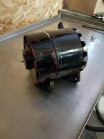
Here goes a trial on posting those pictures:
 

Attachments

  • Alternator 1.jpg
    Alternator 1.jpg
    100.4 KB · Views: 132
  • Alternator 2.jpg
    Alternator 2.jpg
    63.6 KB · Views: 115
  • Alternator 3.jpg
    Alternator 3.jpg
    60.1 KB · Views: 113
  • Alternator 4.jpg
    Alternator 4.jpg
    58.2 KB · Views: 122
  • Alternator 5.jpg
    Alternator 5.jpg
    58.2 KB · Views: 123

MBfreak

MEMBER EMERITUS
Joined
Dec 10, 2010
Messages
2,301
Location
Linkoping , Sweden
MScott.
Thanks for the pics. 1-4 says me nothing. But on pic 5 I think I see 2x3 bolted connections each set close to what I think is a heat sink for the power diodes.
But I can see no sliprings, brushes or an voltage control unit.
I the beginning of the thread was posted a generich schamatic of a typical alternator, and I believe that is what this is.
BUT it can be a PMG unit designed to run at constant speed ( thus almost constant voltage) Inherent current limiting, like most alternators.
If it is a PMG unit the fault is limited to windings, diodes or cracked rotating magnet ( which must be replaced, can not be repaired)

MScott, please try to fix a pic that shows a side view in better detail of pic 5.
Also close up of where the wires out of the unit go.

I am now in Mississippi on my annual vacation, so if yon need to send a part for free repair, no probs as long as not above 2 kilos. Will be done FREE.


Best regards

Ola
 

TheEquineFencer

Well-known member
Joined
Jan 15, 2009
Messages
9,278
Location
Farmville, NC 27828
MScott.
Thanks for the pics. 1-4 says me nothing. But on pic 5 I think I see 2x3 bolted connections each set close to what I think is a heat sink for the power diodes.
But I can see no sliprings, brushes or an voltage control unit.
I the beginning of the thread was posted a generich schamatic of a typical alternator, and I believe that is what this is.
BUT it can be a PMG unit designed to run at constant speed ( thus almost constant voltage) Inherent current limiting, like most alternators.
If it is a PMG unit the fault is limited to windings, diodes or cracked rotating magnet ( which must be replaced, can not be repaired)

MScott, please try to fix a pic that shows a side view in better detail of pic 5.
Also close up of where the wires out of the unit go.

I am now in Mississippi on my annual vacation, so if yon need to send a part for free repair, no probs as long as not above 2 kilos. Will be done FREE.


Best regards

Ola

:+1: Good idea.

At just a glance, it looks like a regular alternator...but as you mentioned, it does not "appear" to have a regulator...

I'd love to see it apart to see what the rotor looks like...a PMG shouldn't have slip rings as the rotor would be comprised of a set of rotating magnets...I wonder if the rotor is like an Onan /Cummins PMG excited generator end? It's been a while since I've had one open or even thought about one as they rarely have a problem...
 

theoldwizard1

Well-known member
Joined
Feb 22, 2011
Messages
43,663
Location
SE MI
I assume picture 4 and 5 are with the back off. Now you need to get the the front off. You will likely need a gear puller to get that pulley. As long as there are no other bolts/nuts holding things together, the rotor should some out with a little "persuasion" on the shaft from the front (use a brass drift or a block of wood).
 

TheEquineFencer

Well-known member
Joined
Jan 15, 2009
Messages
9,278
Location
Farmville, NC 27828
Is it the camera or does the belt look pretty far down in the pulleys?
Could it be slipping?

:thumbup: Bingo! We may have a winner!....

If you look at the belt zoomed in, the outside edges are rolled up. The belt might be bottomed out and slipping under a load. Maybe not enough to make it smoke yet, but it looks like the wrong belt for that pulley.
 
OP
M

MScott

Well-known member
Joined
Jun 30, 2009
Messages
1,616
Location
Eastern Ontario
MScott.
Thanks for the pics. 1-4 says me nothing. But on pic 5 I think I see 2x3 bolted connections each set close to what I think is a heat sink for the power diodes.
MScott, please try to fix a pic that shows a side view in better detail of pic 5.
Also close up of where the wires out of the unit go.

Hope these are what you want.
 

Attachments

  • Alternator 8.jpg
    Alternator 8.jpg
    60.9 KB · Views: 76
  • Alternator 7.jpg
    Alternator 7.jpg
    59.5 KB · Views: 75
  • Alternator 6.jpg
    Alternator 6.jpg
    60.1 KB · Views: 83
OP
M

MScott

Well-known member
Joined
Jun 30, 2009
Messages
1,616
Location
Eastern Ontario
Is it the camera or does the belt look pretty far down in the pulleys?
Could it be slipping?

:thumbup: Bingo! We may have a winner!....

If you look at the belt zoomed in, the outside edges are rolled up. The belt might be bottomed out and slipping under a load. Maybe not enough to make it smoke yet, but it looks like the wrong belt for that pulley.

Actually that was a trial I made. It usually uses a 5/8" belt and I thought maybe it could be slipping so I tried a 1/2" belt to see if that made a difference. Unfortunately it didn't. :( The thinner belt was still on it when the pictures were taken.
 

TheEquineFencer

Well-known member
Joined
Jan 15, 2009
Messages
9,278
Location
Farmville, NC 27828
Actually that was a trial I made. It usually uses a 5/8" belt and I thought maybe it could be slipping so I tried a 1/2" belt to see if that made a difference. Unfortunately it didn't. :( The thinner belt was still on it when the pictures were taken.

:(

Oh, well, I thought we might have hit on something.

It looks like you are getting good with taking pictures....

Put some light on the alternator and see if you can get a picture of the "guts" inside, the rotor and such. Hell, if it doesn't work, take the pulley off and take it apart. If it is a PMG, it shouldn't have any brushes to jump out...
 

MBfreak

MEMBER EMERITUS
Joined
Dec 10, 2010
Messages
2,301
Location
Linkoping , Sweden
Mscott.
The two new pics clearly shows the diodes but little else.
I can not see the sliprings or something that could be the voltage regulator.
Please do like " The Fencer" asks.
And again, there may not be any wound rotor, slip rings and voltage regulator if it indeed is a PMG.

But in order to be of any help at all to you, I need to know.
Good pics can help a lot, guessing *****.

Ola
 

TheEquineFencer

Well-known member
Joined
Jan 15, 2009
Messages
9,278
Location
Farmville, NC 27828
Mscott.
The two new pics clearly shows the diodes but little else.
I can not see the sliprings or something that could be the voltage regulator.
Please do like " The Fencer" asks.
And again, there may not be any wound rotor, slip rings and voltage regulator if it indeed is a PMG.

But in order to be of any help at all to you, I need to know.
Good pics can help a lot, guessing *****.

Ola

:thumbup::+1:
 

MBfreak

MEMBER EMERITUS
Joined
Dec 10, 2010
Messages
2,301
Location
Linkoping , Sweden
MScott.
Let us assume that it is a PMG, ie the rotating field is from a magnet that spins.
It is then quite simple. If it worked before but not now it MAY be that somehow it was connected to the battery with reversed polarity. This will in fractions of a second burn out the diodes.

If you have access to a basic DVM with a diode test function ( often shown as a diode on the face of the dvm) it is very simple to test. ( Also possible to use a 9 V battery and a 12 V 2W lamp)

There are two sets of each three diodes. The heatsink going to the positive output have normal polarity screw in diodes, ie the cathode in the casing,
The other three are reverse polarity, with the anode in the housing.
Do like this :
Unscrew all 6 wire connections , they seem to be fastened with a screw, washer and nut.
Bend the wires a bit to the side so they do not touch.
Attach one of the test leads from the DVM to the heatsink the diodes are screwed in to. Put the DVM in diode test position. Touch each terminal ( where the wire was ) with the other test lead. The readings shall be either open circuit or about 0,56 , which is the forward drop voltage of a typical diode. Reverse the test leads and you will have either open circuit or 0,56.
If both polarities are open circuit or close to zero that diode is damaged.
Repeat for the other three diodes, same result but different polarity.

If a diode, or several are damaged ( most overcurrent faults in diodeds lead to open circuit) the generator voltage under load will drop a lot.

In your generator , replacing a diode is easy. Unscrew, read the type ( typically 1N and 4 more digits) Get new , attach and you are OK.

But, better pictures showing rotor, sliprings, voltage reg is a must if it is not a PMG

Ola
 
OP
M

MScott

Well-known member
Joined
Jun 30, 2009
Messages
1,616
Location
Eastern Ontario
It doesn't appear that I can dismantle the alternator to examine the guts. I tried to remove the aluminum (fan??) on the pulley end with a gear puller but it didn't budge and I applied enough force that the "fan" started to flex and I was afraid that it would break.
I am almost positive, however, that this is a PMG since, when rotating it by hand, you can feel a distinct magnetic "notchiness" (if that's a word) to the rotation.
I will try the steps you have suggested to see if they work.
MBfreak, I really appreciate your attempts to help me out here and your offer of free repair. Unfortunately, the alternator weighs considerably more than 10 kg so it would not be feasible to mail the entire unit to you. I also appreciate the help all the other members have given.:bowdown:
 

MBfreak

MEMBER EMERITUS
Joined
Dec 10, 2010
Messages
2,301
Location
Linkoping , Sweden
MScott,
hope you have not given up. :shocking:
The checking of the diodes is real easy, if you are not sure buy a cheap little diode and learn how to do it on the bench on a new diode, after that the test of the built in parts will be real easy.

Repairing your own stuff is an excellent way to learn and also get a feeling of that you actually OWN the machine. It´s all about facts, no maybes, couldn´t somebody.....

To get in the mood, read " Shop Class as Soul Craft" by Matthew Crawford.

Best regards

Ola
 
OP
M

MScott

Well-known member
Joined
Jun 30, 2009
Messages
1,616
Location
Eastern Ontario
I have not given up but I have put the diagnosis on the back burner for a while. I was able to source a replacement alternator that was designed for a 48 volt system for considerably less than the original estimate so the urgency has been removed. I intend to do the diode checking you suggested and, if successful, will keep the PMA as a backup.
Thanks again for your help.:beer:
 
To avoid these ads, REGISTER NOW!
OP
M

MScott

Well-known member
Joined
Jun 30, 2009
Messages
1,616
Location
Eastern Ontario
The saga continues. Unfortunately, the replacement alternator proved to be useless and I am now in the process of returning it. It put out a maximum of 47.8 volts which obviously is not enough to charge a 48 volt battery pack.
I have been inspecting the original alternator and have been able to dismantle it at least partially. It is definitely a PMA and the magnet ring does not appear to be cracked or broken. There is also continuity in the coil wiring so that does not seem to be the problem. I checked the diodes and all appear to be OK.
I did, however, find what I think is the problem. There is what appears to be a solid state device that I am attaching pictures of. It appears to have a small burn mark (hole) in the plastic "sealant" covering it. (right beside the blue square device in the centre.) I am guessing this may be a voltage regulator but I really don't know.

Does anyone know what this is, how (or if) it can be tested and whether a replacement can be sourced?

The photo is not clear but the blue device has some writing on it. The part that is cut off in the photo (sorry) says "Costa Rica" and wrapped around the centre screw is what appears to be "BOURVS 386". (Not sure of the "V") The unit also is stamped "48V" on the side.

Any assistance is appreciated.
 

Attachments

  • Mystery 1.jpg
    Mystery 1.jpg
    40.1 KB · Views: 70
  • Mystery 2.jpg
    Mystery 2.jpg
    58.5 KB · Views: 66
  • Mystery 3.jpg
    Mystery 3.jpg
    32.9 KB · Views: 65

TheEquineFencer

Well-known member
Joined
Jan 15, 2009
Messages
9,278
Location
Farmville, NC 27828
The saga continues. Unfortunately, the replacement alternator proved to be useless and I am now in the process of returning it. It put out a maximum of 47.8 volts which obviously is not enough to charge a 48 volt battery pack.
I have been inspecting the original alternator and have been able to dismantle it at least partially. It is definitely a PMA and the magnet ring does not appear to be cracked or broken. There is also continuity in the coil wiring so that does not seem to be the problem. I checked the diodes and all appear to be OK.
I did, however, find what I think is the problem. There is what appears to be a solid state device that I am attaching pictures of. It appears to have a small burn mark (hole) in the plastic "sealant" covering it. (right beside the blue square device in the centre.) I am guessing this may be a voltage regulator but I really don't know.

Does anyone know what this is, how (or if) it can be tested and whether a replacement can be sourced?

The photo is not clear but the blue device has some writing on it. The part that is cut off in the photo (sorry) says "Costa Rica" and wrapped around the centre screw is what appears to be "BOURVS 386". (Not sure of the "V") The unit also is stamped "48V" on the side.

Any assistance is appreciated.

It looks like a voltage regulator of some sort to me. The pot is for making adjustments. See if you can post higher resolution pictures.
 

TheEquineFencer

Well-known member
Joined
Jan 15, 2009
Messages
9,278
Location
Farmville, NC 27828
Do a drawing/wiring diagram of what you have and the connections when you have time, that'll help some and some pictures of the diodes layout and such. I think you're going to find it's probably a 48V alternator with the regulator cranked wide open.

I'm guessing you can rewire it so there's no regulator, just the coil windings going through the diode block straight to the batteries and the Voltage will then be regulated by the state of charge the batteries have...if the alternator can handle the load. But then if you do not cut the generator off when the batteries are topped off it'll cook the batteries.
 

theoldwizard1

Well-known member
Joined
Feb 22, 2011
Messages
43,663
Location
SE MI
There is also continuity in the coil wiring so that does not seem to be the problem. I checked the diodes and all appear to be OK.
Also check the coils for shorts to ground or short to other coils.

The photo is not clear but the blue device has some writing on it. The part that is cut off in the photo (sorry) says "Costa Rica" and wrapped around the centre screw is what appears to be "BOURVS 386". (Not sure of the "V") The unit also is stamped "48V" on the side.
The writing on the blue piece is BOURNS. They just made the little blue part.
The blue thing is either a multi-position switch or (more likely) a potentiometer


Here is a shot in the dark. It could be a Prestolite Leece-Neville 48V alternator.
 
Last edited:
OP
M

MScott

Well-known member
Joined
Jun 30, 2009
Messages
1,616
Location
Eastern Ontario
It looks like a voltage regulator of some sort to me. The pot is for making adjustments. See if you can post higher resolution pictures.

That is about the limit of my photo equipment, unfortunately. I took several shots and the one posted was the best. The blue "pot" is only about 3/8" square.
 

theoldwizard1

Well-known member
Joined
Feb 22, 2011
Messages
43,663
Location
SE MI
It took me a few minutes to think of this. If this a truly a permanent magnet alternator, then there would be no voltage regulator ! A voltage regulator works by adjusting the voltage/current applied to the field.

Also, a PMA will (likely) have no brushes.
 

TheEquineFencer

Well-known member
Joined
Jan 15, 2009
Messages
9,278
Location
Farmville, NC 27828
It took me a few minutes to think of this. If this a truly a permanent magnet alternator, then there would be no voltage regulator ! A voltage regulator works by adjusting the voltage/current applied to the field.

Also, a PMA will (likely) have no brushes.

Unless it has some funky diode set up that allows it to regulate it...it could have a PMG that generates the voltage for the regulator. and excitation ..sort of like the newer Cummins PCC generators. I'd like to see inside the generator/rotor assembly.
 

LifeLongWNYer

Well-known member
Joined
Oct 23, 2013
Messages
1,231
Location
South of Rochester, NY
MScott, very interesting thread, I'm enjoying it. Although if has been quite some time since I was in the Army, that alternator looks extremely like a military vehicle unit. So, in an attempt to minimize the inventory of parts, the government attempted to utilize many parts on several/many different vehicles.

Have you tried sending your pictures to the sellers surplus/used military vehicles, asking for help in identifying the alternators, and the possibility of repairing it? I understand freight is not inexpensive, but it might be less expensive to ship it out, have it reapaied and ship it back , than to buy a different ( working ) alternator.

In any event, if you purchase another Abrams tank, just to get the alternator, the remainder of the tank will be a conversation piece in your front year.


.
 

TheEquineFencer

Well-known member
Joined
Jan 15, 2009
Messages
9,278
Location
Farmville, NC 27828
MScott, very interesting thread, I'm enjoying it. Although if has been quite some time since I was in the Army, that alternator looks extremely like a military vehicle unit. So, in an attempt to minimize the inventory of parts, the government attempted to utilize many parts on several/many different vehicles.

Have you tried sending your pictures to the sellers surplus/used military vehicles, asking for help in identifying the alternators, and the possibility of repairing it? I understand freight is not inexpensive, but it might be less expensive to ship it out, have it reapaied and ship it back , than to buy a different ( working ) alternator.

In any event, if you purchase another Abrams tank, just to get the alternator, the remainder of the tank will be a conversation piece in your front year.


.

http://www.whiteowl.com/index.html
 

Dingleburry

Well-known member
Joined
Mar 2, 2016
Messages
593
Location
Great white north in an igloo
This might be a last ditch effort, but everything weve ever needed motor/motor related/rewind/parts etc (which is ALOT) we use IPS. It seems your generator shop isnt too helpful. Try giving these guys a call.
http://www.ips.us/locations/ very happy woth their service. Like i said last ditch effort, you will have to ship it. Oh yeah they specialize in generators also..
 
OP
M

MScott

Well-known member
Joined
Jun 30, 2009
Messages
1,616
Location
Eastern Ontario
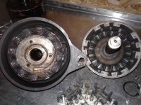
Still working on this problem. I apologize for not updating this thread but life has gotten in the way. I have calls in to several of the sources named but no useful responses yet. I am enclosing a shot of the interior of the alternator for those who asked. I appreciate the information from everyone who has commented,
 

Attachments

  • Interior.jpg
    Interior.jpg
    129.4 KB · Views: 57

MBfreak

MEMBER EMERITUS
Joined
Dec 10, 2010
Messages
2,301
Location
Linkoping , Sweden
M Scott-
The latest pics does not tell me too much, I would have loved to see the rotor in full view pulled out.
However
The pics in post 62 clearly shows a voltage regulator assy. The three wires with lugs on go to each phase, ply connected on the main rectifier bridge diodes ob the AC side. The two pigtails are the wires to the brush holder assy, supplying current to the rotor winding thru brushes riding on the sliprings. There is a metallic "grommet", probably the regulator ground connection. Also a screw post, which likely needs to be connected to battery plus thru a 12V 5 W lamp. This will supply some magnetizing current at start up, once the AC is being generated that will be used as pwr for the magnetizing rectifier/regulator. Without the lamp the generator may not function, depending on the amount of magnetic remanence in the rotor iron.The little blue part is a Bourns 3/4 turn potentiometer, used to set voltage output.

In other words, pic 62 makes me believe that the unit is a std design alternator, 3 phase stator winding , 3 phase power bridge rectifier, wound rotor with sliprings, carbon brushes and an exciter unit with built in low power three phase rectifier/regulator. (post 62 pic)
Any auto electrical handbook will show and explain the fuction.

If the assyin pic 62 is shot, just replace it. Any decent auto electrical shop should be able to get the generator back in service.

And any half baked electronics engineer will be able to build a piggy-back exciter unit, if a spare can not be found and the orig unit can not be opened.

I put a bad mojo on all mfrs that pot their electronics in epoxy!

And I had a great time in the Delta, 3 weeks of bliss at the Shack Up Inn in Clarksdale, Mi.

All the best

Ola
 

TheEquineFencer

Well-known member
Joined
Jan 15, 2009
Messages
9,278
Location
Farmville, NC 27828
Still working on this problem. I apologize for not updating this thread but life has gotten in the way. I have calls in to several of the sources named but no useful responses yet. I am enclosing a shot of the interior of the alternator for those who asked. I appreciate the information from everyone who has commented,

If you can, post a better picture of the diode block so we can see it a little better. I'd get some contact cleaner and wash the alternator windings out too.

From the looks of it, I can't tell for sure, does the rotor on the right have Magnet's made to it?

Are there brushes in this? I'm guessing the diodes were bolted to the windings and rotated with it? Or is the windings fixed in place and the magnets rotated?

If it's like I think it is, you'd have three pair of wires going from the windings to the diode block. Check each pair for a short to the other two pairs, it should read an open or "OL", also check to see if the resistance is the same or close. Then check the diode blocks for a short and/or open.
 

theoldwizard1

Well-known member
Joined
Feb 22, 2011
Messages
43,663
Location
SE MI
From the looks of it, I can't tell for sure, does the rotor on the right have Magnet's made to it?
My guess is YES ! The 8 "indents" that look like the have a screw or rivet in them.

Are there brushes in this? I'm guessing the diodes were bolted to the windings and rotated with it? Or is the windings fixed in place and the magnets rotated?
Likely no brushes (PM alternators do not have brushes because no power is sent to the field). The piece on the right is the field that is rotated by the shaft. The windings are fixed. The magnets pass by the stator in that area between the windings and the outer housing.

Of course no the question is how is voltage regulated ? Here is my SWAG. Because the engine runs at a constant speed the voltage IS fairly constant, but probably a bit higher than really required. The voltage regulator simply shunts excess voltage to ground (zener diode and resistor) making heat. Not the most efficient but if the RPM is constant and correct, then it is not much of a waste. A design like this is EXCELLENT for alternators that need to run many, MANY hours with zero maintenance. The only "wear" parts are the bearings.

As long as all of the diodes check out and there are no shorts from any of the stator windings to another winding or to the case, the problem is strictly in the voltage regulator.
 
Last edited:
OP
M

MScott

Well-known member
Joined
Jun 30, 2009
Messages
1,616
Location
Eastern Ontario
M Scott-


In other words, pic 62 makes me believe that the unit is a std design alternator, 3 phase stator winding , 3 phase power bridge rectifier, wound rotor with sliprings, carbon brushes and an exciter unit with built in low power three phase rectifier/regulator. (post 62 pic)
All the best

Ola

This alternator definitely does NOT appear to be a std. design alternator. There are no brushes or slip rings. The device on the right in post 73 contains magnets ( the centre block in each group of 3 blocks is a magnet) and it rotates around the core which consists of two separate windings. There was no provision for a power source to magnetize. Unless I am completely off base, this is a PMA.
 
OP
M

MScott

Well-known member
Joined
Jun 30, 2009
Messages
1,616
Location
Eastern Ontario
From the looks of it, I can't tell for sure, does the rotor on the right have Magnet's made to it?

Are there brushes in this? I'm guessing the diodes were bolted to the windings and rotated with it? Or is the windings fixed in place and the magnets rotated?

If it's like I think it is, you'd have three pair of wires going from the windings to the diode block. Check each pair for a short to the other two pairs, it should read an open or "OL", also check to see if the resistance is the same or close. Then check the diode blocks for a short and/or open.

There are no brushes. The rotor does contain magnets and rotates around the fixed windings. We have checked the wires and windings and there is some resistance but no shorts to ground. The diodes have also checked out.
 
OP
M

MScott

Well-known member
Joined
Jun 30, 2009
Messages
1,616
Location
Eastern Ontario
My guess is YES ! The 8 "indents" that look like the have a screw or rivet in them.


Likely no brushes (PM alternators do not have brushes because no power is sent to the field). The piece on the right is the field that is rotated by the shaft. The windings are fixed. The magnets pass by the stator in that area between the windings and the outer housing.

Of course no the question is how is voltage regulated ? Here is my SWAG. Because the engine runs at a constant speed the voltage IS fairly constant, but probably a bit higher than really required. The voltage regulator simply shunts excess voltage to ground (zener diode and resistor) making heat. Not the most efficient but if the RPM is constant and correct, then it is not much of a waste. A design like this is EXCELLENT for alternators that need to run many, MANY hours with zero maintenance. The only "wear" parts are the bearings.

As long as all of the diodes check out and there are no shorts from any of the stator windings to another winding or to the case, the problem is strictly in the voltage regulator.

This is my take as well. The question is where can I obtain a replacement voltage regulator?
 

TheEquineFencer

Well-known member
Joined
Jan 15, 2009
Messages
9,278
Location
Farmville, NC 27828
This is my take as well. The question is where can I obtain a replacement voltage regulator?

Very carefully take the one you have apart and see how it's built, then see what you need. I'm trying to picture how to regulate the output on a PMG. The magnets will be making A/C voltage rotating inside the windings, the diodes rectify it to DC for the output, it would have to somehow limit the voltage/current at the diodes. :headscrat I wonder if the Diodes are big Zeners?:headscrat

Drawing out the connection and posting may help.
 
To avoid these ads, REGISTER NOW!
Top Bottom