To avoid these ads, REGISTER NOW!

Alternator Problem

To avoid these ads, REGISTER NOW!

AntonLargiader

Well-known member
Joined
Nov 20, 2016
Messages
1,372
Location
Charlottesville, VA
I work on some motorcycles that have PMAs. Standard troubleshooting is:

1) test all three stator windings to ground (should not find any; they should all be isolated). Testing one should do the trick since they are interconnected but test all of them.

2) Test the stator windings' resistances: 1-2, 2-3, 3-1. Should be similar. I usually see numbers in the 7~14 range but who knows with the one you have.

3) Run the motor slowly with the windings unplugged and measure the AC voltage at each of the three terminals. You should see a voltage well in excess of the DC voltage you are looking for. You may need to carefully increase speed but do so slowly while monitoring the voltage. For my 12V systems I typically see about 28V with minimal engine revving. That's all I need to see.

4) If you have sufficient AC voltage at the three windings and insufficient DC voltage coming out of the R/R (regulator/rectifier), then you have a bad R/R. And yes of course these have regulators. They are typically shunt type that divert excess current to ground. It's not as inefficient as you may think. There are also series type regulators and you can Google the difference.
 

theoldwizard1

Well-known member
Joined
Feb 22, 2011
Messages
43,666
Location
SE MI
If you have a friend who is a bit handy with electronics you can BUILD you own regulator for not a lot of money. The key is to use a Zener diode close to your desired set voltage that turns on/off a Triac connected to the positive output of each diode pair.

This NOT a good example, for several reasons. Ignore the full wave bridge rectifiers (you have all the diodes your need) and of course the zener is the wrong value. The ULN2003 transistor will not handle your voltage. A lot of "compromises" were made to make this device small and easy to build.

HOW TO MAKE A RELIABLE MOTORCYCLE VOLTAGE REGULATOR
 

theoldwizard1

Well-known member
Joined
Feb 22, 2011
Messages
43,666
Location
SE MI
Okay, time to stop screwing around and get this thing running !

Assumptions:


  • This is a permanent magnet alternator. All stator windings are good (no opens or shorts) and the magnets are all in their proper places.
  • The diodes (there should be 6 individual diodes or 3 pairs) are also good.

Without the regulator installed, these can be confirmed by spinning the alternator and checking for voltage on the positive terminal and ground (assuming the positive leads from the diodes all go to a common positive terminal). The voltage produced at normal RPM is not to critical, but it should be around 60V. (Much lower and you likely have a a bad diode.)

PM alternators are common in windmills and they also use higher voltage battery banks. So what do the do ?

Battery Voltage Regulators

Scroll down the page about half way to find the section on 24V, 36v and 48 V regulators.

adg500dt2.jpg


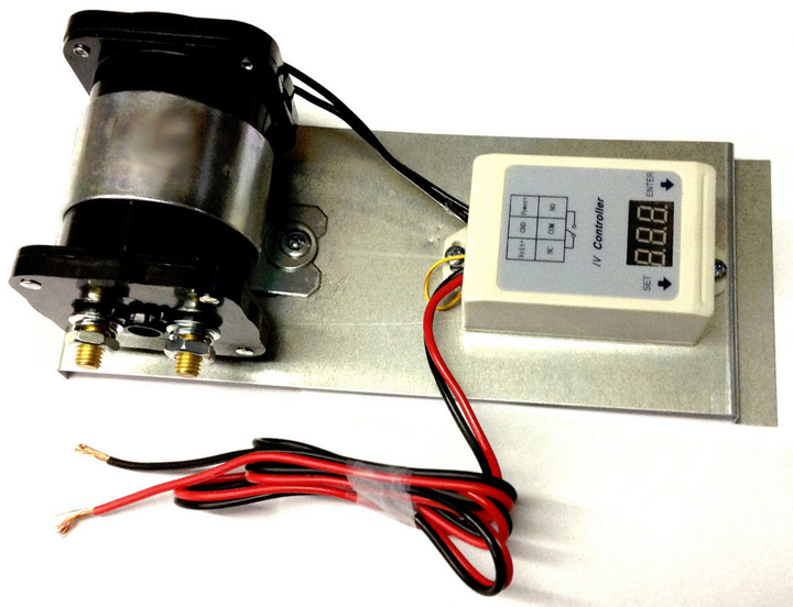
That gigantic relay simply cuts power from the alternator to the battery bank ! If you watch the associate video, you see that the controller is adjustable/programmable in many way. My only concern is how many cycle is that relay designed to handle ? 1M ? 10M, 100M?

It is certainly worth a phone call to this place !
 
Last edited:
OP
M

MScott

Well-known member
Joined
Jun 30, 2009
Messages
1,616
Location
Eastern Ontario
I currently have the alternator torn apart (everyone wanted to see pics of the internals) so I can't test the output. I have calls in to try and source a replacement voltage regulator since that would be my best chance of getting this working. Building a regulator is WAY beyond my level of expertise but replacing it with an "battery located" one is certainly a last ditch possibility. Right now I'm waiting for answers on whether the current regulator can be replaced but thanks for the suggestions.
 

MBfreak

MEMBER EMERITUS
Joined
Dec 10, 2010
Messages
2,301
Location
Linkoping , Sweden
Post 81 is probably the best input to the thread. Thanks to Equine Fencer for digging it up. Great to learn something new!
It is old technology and about the same princple was used extensively in the 50-60´s for speed control of DC motors. Thyratron rectifiers and magnetic amplifiers. Great stuff, time constants of many seconds!
So there is a voltage control part ( the pic from 61) .
OP , i would be pleased to repair it for you free of all costs. However, if it is epoxy potted it can most probably not be repaired, at least I do not know how to get hardened epoxy off without damaging whatever is inside.

Let me know if you need help and I will PM you my adress.

Ola
 

TheEquineFencer

Well-known member
Joined
Jan 15, 2009
Messages
9,278
Location
Farmville, NC 27828
Post 81 is probably the best input to the thread. Thanks to Equine Fencer for digging it up. Great to learn something new!
It is old technology and about the same princple was used extensively in the 50-60´s for speed control of DC motors. Thyratron rectifiers and magnetic amplifiers. Great stuff, time constants of many seconds!
So there is a voltage control part ( the pic from 61) .
OP , i would be pleased to repair it for you free of all costs. However, if it is epoxy potted it can most probably not be repaired, at least I do not know how to get hardened epoxy off without damaging whatever is inside.

Let me know if you need help and I will PM you my adress.

Ola

You can take a dremel tool and start "whittling" away at the epoxy and gradually cut it apart a lot of the time to get to what is inside, then reverse engineer it.
 
To avoid these ads, REGISTER NOW!
OP
M

MScott

Well-known member
Joined
Jun 30, 2009
Messages
1,616
Location
Eastern Ontario
Thank you for the offer Ola, but it appears that the device is coated with epoxy which probably means it is not repairable.
I am still trying to locate a replacement regulator but without success to date. The remote voltage regulator mentioned by Wizzard is a possibility, but I would have to figure out how to rewire the alternator to bypass the defective regulator.
Does anyone understand the purpose of the second winding that is behind the coils shown on the left in post 73. The ones you can see in the front are wound around the 12 radial poles but behind that is another winding that appears to be circumferential. It is not obvious how that coil is wired in.:confused:
 

TheEquineFencer

Well-known member
Joined
Jan 15, 2009
Messages
9,278
Location
Farmville, NC 27828
Thank you for the offer Ola, but it appears that the device is coated with epoxy which probably means it is not repairable.
I am still trying to locate a replacement regulator but without success to date. The remote voltage regulator mentioned by Wizzard is a possibility, but I would have to figure out how to rewire the alternator to bypass the defective regulator.
Does anyone understand the purpose of the second winding that is behind the coils shown on the left in post 73. The ones you can see in the front are wound around the 12 radial poles but behind that is another winding that appears to be circumferential. It is not obvious how that coil is wired in.:confused:

I'm going to send you a PM, so check your messages please.
 

TheEquineFencer

Well-known member
Joined
Jan 15, 2009
Messages
9,278
Location
Farmville, NC 27828
If it has TWO set's of windings like it now sounds like it does, That really makes things interesting...goes back to drawing out a wiring diagram of what you have and the connections... that would help a lot...
 

MBfreak

MEMBER EMERITUS
Joined
Dec 10, 2010
Messages
2,301
Location
Linkoping , Sweden
Without going to deep, the second winding is the control winding. It gives a partial saturation of the iron cores , when fed by a current, around which the "power windings" are wound.
The partially saturated iron core will generate a lower voltage from the virtually fixed rotating magnetic field from the PM rotor.

50/60s technology used in other applications, but has never even heard of it in an alternator. Pretty complicated way to avoid a wound rotor, sliprings, carbon brushes. But, if the objective was to create a maintenance free, non sparking alternator, it was a winner .

Modern designs with no sliprings are common, has a separate rotating exciter/rectifier unit with a fixed magnetizing field.

Ola
 
OP
M

MScott

Well-known member
Joined
Jun 30, 2009
Messages
1,616
Location
Eastern Ontario
Sorry Wiz, I've been away and haven't been following up. My solar guy (the original supplier of the alternator) has promised to try to get me a replacement regulator from the manufacturer in Arizona. He hasn't gotten back to me so I think it's about time I became a "squeaky wheel" and started pushing him. Fortunately, at this time of year back up power is rarely needed so it hasn't been a priority for me.
 
To avoid these ads, REGISTER NOW!
Top Bottom