To avoid these ads, REGISTER NOW!

Another magnetic starter/compressor wiring question...

jewellboy

Member
Joined
Dec 29, 2005
Messages
23
Location
Virginia
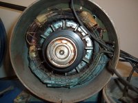
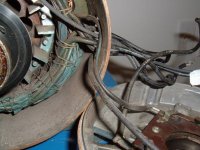
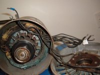
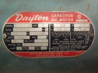
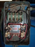
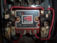
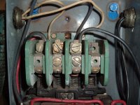
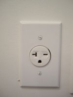
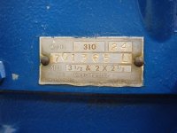
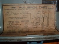
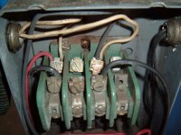
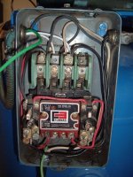
Well, I've been reading for a couple of hours now and I am still pretty confused. I have a Quincy model 310 compressor with a 2 hp Dayton motor that I have been working on rebuilding and putting back together for some time now. I am in the final stages and I need to figure out how to rewire the motor/starter/pressure switch. I am unsure of the wiring in the mag starter as it was changed since I initially removed it from the unit. I also would appreciate it if someone could confirm whether or not I have the proper plug setup for my situation. I think I understand how the pressure switch is to be wired but a little more clarity is never a bad thing. Hopefully the pictures below will give the necessary info on my setup and I can take more if needed. Thanks in advance for any help that you folks can provide. I wanna get this thing running and get to work!
 

Attachments

  • DSCF2639-2.jpg
    DSCF2639-2.jpg
    57.8 KB · Views: 50
  • DSCF2640-2.jpg
    DSCF2640-2.jpg
    54.5 KB · Views: 62
  • DSCF2641-2.jpg
    DSCF2641-2.jpg
    59.4 KB · Views: 49
  • DSCF2642-2.jpg
    DSCF2642-2.jpg
    61.8 KB · Views: 46
  • DSCF2646-2.jpg
    DSCF2646-2.jpg
    29.3 KB · Views: 32
  • DSCF2652-2.jpg
    DSCF2652-2.jpg
    45.6 KB · Views: 36
Last edited:
To avoid these ads, REGISTER NOW!

mrb

Well-known member
Joined
Dec 31, 2008
Messages
3,734
that receptacle is a NEMA 6-20 20 amp 250vac. I have plugs that fit it if you need one.
 
OP
J

jewellboy

Member
Joined
Dec 29, 2005
Messages
23
Location
Virginia
Thanks mrb. I actually have the plug, but I may want to get a right angle version down the road as I can see myself becoming annoyed with this one sticking straight out from the wall.
 

JBurgess

Well-known member
Joined
Mar 1, 2008
Messages
372
Location
Arizona
Can you get a picture looking down the direction of the arrrow?

DSCF2642-2.jpg


Also I can't make out the terminals on the pressure switch from the photo, even with my glasses.

Do you know for sure the motor is wired for 230?

What are you using for a power cord?
 

Norcal

Well-known member
Joined
Mar 16, 2008
Messages
13,752
Is there a wiring diagram inside the starter cover? That would be what you need to connect the unit.
 
OP
J

jewellboy

Member
Joined
Dec 29, 2005
Messages
23
Location
Virginia
Here's a few more pics. Cant seem to figure out how to embed the larger versions. The motor is definately wired for 220. The cord has the proper 6-20 plug on it for the receptacle - it's 12 ga and I can easily change it to 10 if needed. The last couple of pics are the stickers that are on the inside of the cover on the starter. I just dont understand enough about this mag starter to know what the heck I am doing without some guidance. Thanks again guys. Oh yeah, I also uploaded a better pic of the pressure switch.
 

Attachments

  • DSCF2666-2.jpg
    DSCF2666-2.jpg
    44.2 KB · Views: 21
  • DSCF2665-2.jpg
    DSCF2665-2.jpg
    53.3 KB · Views: 25
  • DSCF2675-2.jpg
    DSCF2675-2.jpg
    43.5 KB · Views: 17
  • DSCF2670-2.jpg
    DSCF2670-2.jpg
    52.7 KB · Views: 20
  • DSCF2668-2.jpg
    DSCF2668-2.jpg
    53.4 KB · Views: 26

JBurgess

Well-known member
Joined
Mar 1, 2008
Messages
372
Location
Arizona
For the pressure switch use theses 2 terminals (green arrows). A ground wire would be good. Be sure wires will not rub against cut end of flex (red arrows).

DSCF2670-2.jpg


For the starter run the power to L1 and L2 (back row). Be sure to hook up the ground. It would be good to have a ground wire in the flex to the motor also.

Move the white and blue (maybe black) to the terminal shown or you could wire nut them together. Leave the red and other white where they are on L2 and L1.

DSCF2668-2.jpg


It is best if wires in the flex are stranded so they survive vibration better. That contactor is old. I would guess '50s vintage. My mid sixties equipment has a newer version. Your compressor looks to be newer 1970 I think.
 
OP
J

jewellboy

Member
Joined
Dec 29, 2005
Messages
23
Location
Virginia
Thanks for the reply J. The unit is definately old. I actually got the whole setup for free from someone that was told "It's gonna cost more to fix it than this thing is worth" Obviously they didn't how much these things go for. Neither did I, at the time. The compressor has been completely rebuilt and painted, tank hydrostatically tested and repainted and the motor has also been tested. When the guys tested the motor, I mistakenly told them that there wasnt going to be a pressure switch used (not sure why I did that) and they rewired the starter accordingly. I'll give your pics and shot and report back with my results.
 

Offshore

Member
Joined
Jul 31, 2009
Messages
5
Location
Iberia Parish, LA.
Hi, kind of new here.

Am I missing something or can this small motor run directly off the
pressure switch? Don't see the pressure switch rating.

I have a 310 compressor too. Put an oil filter on it by replacing the oil pump end with one from a junk 5120 compressor.
 
OP
J

jewellboy

Member
Joined
Dec 29, 2005
Messages
23
Location
Virginia
How do you like your 310? I've owned this one for almost ten years, but thru a series of events, have never actually used it myself. I'm thinking that there won't be much that I will need in my garage that it can't do, but I would be interested to hear your take on it.
 

930dreamer

Super Moderator
Staff member
Joined
Oct 7, 2009
Messages
22,945
Location
Amarillo,TX and Stinnett,TX
I'm in the same situation. Trying to wire a motor starter and pressure switch. The compressor starts without the motor starter, but when I add it I get nothing. The coil isn't closing the switch. Can I close it with a screwdriver with the power on? It's wired 240v 3 phase. For the pressure switch do I use all the load and line screws(4) total?

 
Last edited:

Offshore

Member
Joined
Jul 31, 2009
Messages
5
Location
Iberia Parish, LA.
I've had this 310 for about 5 years. Got it new and right out of the box, had blown head gasket. Always had problems with the unloader valve bleeding air while running. I put a 3 hp motor on mine and determined the max speed and bought a pulley for that RPM.
It will pump a 120 gallon tank to 120 psi in 15.5 minutes so guess it's working ok. The tank is drained with a stainless steel float valve which seems to work good, never found much water in it.

The motor is controlled by a pressure switch without a motor starter. I might install one just for a method of shutdown due to low oil pressure.
 

Offshore

Member
Joined
Jul 31, 2009
Messages
5
Location
Iberia Parish, LA.
I'm in the same situation. Trying to wire a motor starter and pressure switch. The compressor starts without the motor starter, but when I add it I get nothing. The coil isn't closing the switch.

Have you tried the reset for the overload heaters? I'm not familiar this motor starter but it has to have one.
 

JBurgess

Well-known member
Joined
Mar 1, 2008
Messages
372
Location
Arizona
I'm in the same situation. Trying to wire a motor starter and pressure switch. The compressor starts without the motor starter, but when I add it I get nothing. The coil isn't closing the switch. Can I close it with a screwdriver with the power on? It's wired 240v 3 phase. For the pressure switch do I use all the load and line screws(4) total?


Can you post better picyures of the connections on top of the contactor and the tag on the black wire near the bottom. Where all the pipes go woulld help and what are wiers behind the conduit not in conduit?

On edit if there is a wiring diagam inside the cover that would help also.
 

930dreamer

Super Moderator
Staff member
Joined
Oct 7, 2009
Messages
22,945
Location
Amarillo,TX and Stinnett,TX
Top conduit is 3 phase L1,L2,L3 from converter. Lower left goes to the motor T1,T2,T3, black wire is(T2) the generated line from the RPC. Lower right goes to the pressure switch. Thanks
 
Last edited:

JBurgess

Well-known member
Joined
Mar 1, 2008
Messages
372
Location
Arizona
MOTORSTARTERS010.jpg


A few things,

1. This brown wire appears to attack to an auxiliary terminal that is not hooked to anything else.

2. This brown wire should not hooked up here, it only would get power when the compressor is running. It should hook up to the coil on the contactor. The tag on the black wire below it should be able to confirm which terminal that is.

3. This red wire hooks up to where. A picture looking down on the connections would help.

4. These nuts are normally installed with the teeth down .

I can’t tell from the picture, but are there 4 wires in the left pipe to the motor, with the smaller green wire being the ground for the motor?
 

930dreamer

Super Moderator
Staff member
Joined
Oct 7, 2009
Messages
22,945
Location
Amarillo,TX and Stinnett,TX
1.The brown wires are from the pressure switch. Not sure if I use the L1,L2 for line and T1,T2 for load?
2. the tag tell the amp and volt ratings.
3. The red wire is factory and goes to L2.
4. Bottom left has a ground, T1,T2,T3 to motor.
5. Teeth down got it.

Thanks, Shawn
 

JBurgess

Well-known member
Joined
Mar 1, 2008
Messages
372
Location
Arizona
The coil should get it's power from L1 and L3, if you use the manufactured phase (L2) the voltage may drop during starting causing the contactor to chatter.

MOTORSTARTERS010-Copy.jpg


Arrow 1 move red wire to L3

Arrow 2 move brown wire to L1

Arrow 3 Move brown wire to screw marked W and 3

For wiring inside the pressure switch use L1 and T1

You should also have a ground wire with the incoming power.

I assume you know green wire is normally reserved for use only as the ground.

These heaters need to match the nameplate current of your motor. They are labeled with a size.

PICT0838.jpg
 
To avoid these ads, REGISTER NOW!

930dreamer

Super Moderator
Staff member
Joined
Oct 7, 2009
Messages
22,945
Location
Amarillo,TX and Stinnett,TX
Green wire was used only because I bought a spool for next to nothing and is temporary. I'll check the nameplate current on the motor and move everthing per your directions. Thank you Shawn
 

JBurgess

Well-known member
Joined
Mar 1, 2008
Messages
372
Location
Arizona
OK or goal is get 220V across the coil #2 and #3

If you have a voltmeter with the power on:

Check voltage across #1 and #2 it should read, 0 if not overload is tripped
Check across #4 and #5 it should read 0 also, if not overload is tripped
Check voltage across #3 and L1 it should read 0, if not pressure switch not hooked up right.

Check voltage across L1 and #5 it should read 220V same for L1 to #4, #1 and #2

Check voltage across L2 and #3 it should read 220 V

MOTORSTARTERS010-1.jpg


On edit: H43 heater, is a 7-1/2 HP motor?
 
Last edited:
OP
J

jewellboy

Member
Joined
Dec 29, 2005
Messages
23
Location
Virginia
Time to resurrect an old thread... I finally got around to wiring this compressor today. I travel a lot for work, so this is the first time I've had a chance and was motivated. I used the diagrams and advice I got in this thread, checked everything three times and plugged it in. The motor came on, but was turning very slowly and made quite a lot of noise/vibration. I'm sure there must be something hooked up incorrectly somewhere, I just don't know where. Any ideas? Dying to get this thing up and running, but paranoid that I'll damage the motor somehow...
 

JBurgess

Well-known member
Joined
Mar 1, 2008
Messages
372
Location
Arizona
First suggestion is to be sure the motor is wired for the correct voltage. If by turning very slowly you mean 1 or 2 revaluations per second, look for a bad capacitor or centrifical switch.
 
OP
J

jewellboy

Member
Joined
Dec 29, 2005
Messages
23
Location
Virginia
According to the diagram on the side of the motor, the wiring is correct for 220 (the individual wires are actually numbered on the jacket). Strangely, however, there is one more wire coming out of the motor than there should be. This additional wire is newer than the others and connects directly into the capacitor on the top of the motor. I had the motor checked out a few months ago, and all was well according to the folks who checked it for me. I would say one or two revs per minute would probably be fairly accurate as far as how fast the motor spun when I wired it up. I even checked the wall plug with a mm to verify that it was in fact wired 220. Is the centrifugal switch something that would be in addition to a cap or in place of?
 

JBurgess

Well-known member
Joined
Mar 1, 2008
Messages
372
Location
Arizona
T5 and T8 are the starting circuit. It sounds this motor only has 1 cap from what you said. Your motor will have both a centrifugal switch and a capacitor. They are both in series with the start winding. If either one is bad it will cause the problem you describe. As for the extra wire, a picture would help. Are either T5 or T8 missing?
 
OP
J

jewellboy

Member
Joined
Dec 29, 2005
Messages
23
Location
Virginia
T5 and T8 are both present. The extra wire is attached to the T1 wire along with the wire coming up from the mag starter. T5 and T8 are also switched per the diagram for counter clockwise rotation. I just went out and had a look at the cap and it is a Vangaurd BC 705S which according to this site http://www.superioressex.com/upload...loads/Linecards_and_Catalogs/capacitors_w.pdf
seems to be a 125v unit. Is this correct for a motor running on 220v?
 
OP
J

jewellboy

Member
Joined
Dec 29, 2005
Messages
23
Location
Virginia
Okay, I took a few more pics this morning. I also tested the wires coming out of the mag starter with my dmm and found that when I turn the pressure switch on, 240v does indeed flow thru to the motor end of the wire. The extra wire that I was talking about is the one with the white tape on it that is terminated with the blue spade on the other end at the top of the motor. I do not know why it is there, but I'm not sure how things would be hooked up otherwise. As before, fullsize pics are here http://cid-3cf9e38d80c3b080.skydrive.live.com/browse.aspx/Public/Compressor I really appreciate all this help. This thing has been torn down so long, I dont think I can remember what it sounds like running.
 

Attachments

  • DSCF2727.jpg
    DSCF2727.jpg
    47.6 KB · Views: 3
  • DSCF2724.jpg
    DSCF2724.jpg
    42.3 KB · Views: 4
  • DSCF2723.jpg
    DSCF2723.jpg
    66.3 KB · Views: 3
  • DSCF2722.jpg
    DSCF2722.jpg
    62.5 KB · Views: 3
  • DSCF2718.jpg
    DSCF2718.jpg
    56.5 KB · Views: 9

JBurgess

Well-known member
Joined
Mar 1, 2008
Messages
372
Location
Arizona
The new wire looks to be a replacement for either T5 or T8

Let's check all the windings.

unhook the wires.

T1 and T2 should have continuity with a ohmmeter and to no others
T3 and T4 should have continuity with a ohmmeter and to no others

Hook the 2 wires together that are for the capicitor
Now T5 and T8 should have continuity. I am guessing they do not. See if the new wire and either T5 or T8 have continuity. If so use these 2 as T5 and T8 and tape the left over one.

Replace the capcitor and hook the wires up again and give it a try.
 
OP
J

jewellboy

Member
Joined
Dec 29, 2005
Messages
23
Location
Virginia
All of the conditions of your previous post were met when I tested the wires except:
When I tested T5 and T8 they not only had continuity to one another but also each had continuity with the new wire... Also, is there a wrong way to hook up the cap?

Just did a little more thinking...
According to my above results, those connections make all the wires continuous to one another. I just verified this with the dmm....weird..that additional wire confuses the **** oughtta me..
 
Last edited:

JBurgess

Well-known member
Joined
Mar 1, 2008
Messages
372
Location
Arizona
The cap can be hooked up either way. One wire to each terminal.

Unhook the wires to the cap and check for continuity between T5 T8 and the new wire.

If there is now no continuity between T5 and T8 then tape the new wire and use T5 T8.
 
OP
J

jewellboy

Member
Joined
Dec 29, 2005
Messages
23
Location
Virginia
T5, T8 and the new wire all have continuity. The new wire being hooked to T1 (not sure if I made that clear or not) now causes all of the wires to be continuous to one another when tested. If I tape the new wire, then there will be nothing connected to one side of the cap, as the new wire goes directly from the side of the motor and up to the cap. Any idea which wire would normaily be the one that should be hooked to the cap?

BTW, did I thank you yet for all this help? :)
 

JBurgess

Well-known member
Joined
Mar 1, 2008
Messages
372
Location
Arizona
I don't know if this will help you, but here's the wiring.

motor002.jpg


the c.s. and the capacitor may in reverse order may be on T8 instead of T5, maybe one on each..

With the cacitor disconected and the wires to isolated, what are the ohm readings between the three wires? (T5 T8 and new wire) maybe by this we can guess where they are hooked up.
 
OP
J

jewellboy

Member
Joined
Dec 29, 2005
Messages
23
Location
Virginia
Okay, first for the resistance readings.. the new wire is connected straight from cap out to the T1+Line connection. Once disconnected from both the cap and the T1+Line connection it (obviously) shows an open line when tested with either T5 or T8 (since the "new" wire is no longer connected to anything at all). When resistance is tested between T5 and T8, it hovers from 1.4-1.7. Now, on to the diagram for clockwise rotation. T5 shows as going thru the c.s. then thru the cap and into the motor and back out as T8 (if I'm reading it correctly). On my motor, T5 goes into something that is attached to the center of the back of the motor (c.s.?) and out the top of the housing to where the cap sits (there are three wires connected to this thing attached to the inside back of the motor). Instead of the wire leaving the cap and returning back into the motor, the other wire that connects to the cap is the "new" wire. T2, T8 and T4 all go into the bottom of the winding. T1 (which is connected to "new" and line on the outside of the motor) and T3 both go the the top of the winding. Can I pull the 4 long bolts that run thru the motor out and separate the back end of the motor without screwing things up? This would give me a much better view of how things are wired.
 
OP
J

jewellboy

Member
Joined
Dec 29, 2005
Messages
23
Location
Virginia
Just took that back plate off and snapped some more pics. It looks like the c.s. has three leads hooked to it, which confuses me as everything I've seen points to it only having two.
 

Attachments

  • DSCF2731.jpg
    DSCF2731.jpg
    84.2 KB · Views: 4
  • DSCF2732.jpg
    DSCF2732.jpg
    88.1 KB · Views: 3
  • DSCF2736.jpg
    DSCF2736.jpg
    91.5 KB · Views: 3
  • DSCF2738.jpg
    DSCF2738.jpg
    71.5 KB · Views: 3
  • DSCF2739.jpg
    DSCF2739.jpg
    83.2 KB · Views: 3
  • DSCF2740.jpg
    DSCF2740.jpg
    87.1 KB · Views: 3

JBurgess

Well-known member
Joined
Mar 1, 2008
Messages
372
Location
Arizona
Back home again.

So If I understand T8 goes int the windings, T5 goes to CS, the other 2 wires on the CS, one goes to the windings and the other goes to the capacitor.

Looks like you should remove the new wire completely, then move the winding wire from the CS and hook it to the capacitor.

This will leave T5 and a wire to the capicitor the only 2 wires on the CS.

The capacitor will have a winding wire and a wire to the CS on it.

Make sure the contacts on CS are in reasonable conditition.

Also there is usally a wave washer in the casting under the bearing, be sure it stays in place when reassembling.
 
To avoid these ads, REGISTER NOW!
Top Bottom