AP514
Well-known member
Hey ALL
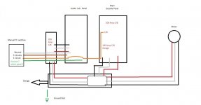
Well the Wife has been on me for the last few week to get the Manual Transfer Switch bought and installed.
So, I am thinking of getting this Switch and changing out the wiring so it is longer. http://www.steadypower.com/products.php?product=Reliance-RA306A-Outdoor-Transfer-Switch-%2830A%29
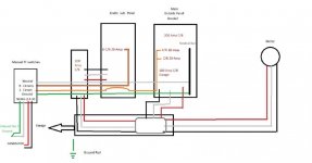
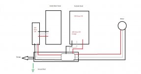
The problem I have is I want to power circuits in 2 separate 200 amp panels.
(see pics)
I see the Main panel outside is Bonded. (Bar - Neutral to Ground)
The outside panel will have 2 circuits and the inside will have the rest (4)
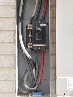
If I can I will run wiring from Manual Switch to the outside Big single CB
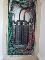
panel.(3rd pic) Then run wiring in with the Large Wires going to the inside Panel.(1st pic lower Rt-hole(pic2)) The 2 outside Circuits will run the same way but come out the inside panel to the outside (pic1 lower L/H -hole...not sure this is LEGAL
Well the Wife has been on me for the last few week to get the Manual Transfer Switch bought and installed.
So, I am thinking of getting this Switch and changing out the wiring so it is longer. http://www.steadypower.com/products.php?product=Reliance-RA306A-Outdoor-Transfer-Switch-%2830A%29
The problem I have is I want to power circuits in 2 separate 200 amp panels.
(see pics)
I see the Main panel outside is Bonded. (Bar - Neutral to Ground)
The outside panel will have 2 circuits and the inside will have the rest (4)
If I can I will run wiring from Manual Switch to the outside Big single CB
panel.(3rd pic) Then run wiring in with the Large Wires going to the inside Panel.(1st pic lower Rt-hole(pic2)) The 2 outside Circuits will run the same way but come out the inside panel to the outside (pic1 lower L/H -hole...not sure this is LEGAL
Attachments

Last edited:


")