The plans do not come with the CAD files. If you ask really really nice and promise not to use them commercially, Rick might give them to you. If he does, it still takes hours of cam work to get them all nested together. They are also drawn for a laser cutter. There's no clearance for the small amount of taper that is usually present when plasma cutting.

You are using an out of date browser. It may not display this or other websites correctly.
You should upgrade or use an alternative browser.
You should upgrade or use an alternative browser.
AR51 Buggy Build
- Thread starter Griff93
- Start date

I'm fine with that as long as I have Ricks permission. I had to promise not to share them with anyone. All the cam work was done for a dynatorch table so I'm sure the post processor would be different for a plasmacam. I might have a post for them. Id have to look. I'd be glad to see another ar51 being built.
Nitrogen is nice. It is "dry" so consumables last a good bit longer and you get a more stable arc. It is not better then dry air, but in reality it is hard to get really dry air. Even with a refrigerated condenser, a drier, and a filter a decent amount of water vapor gets through. The problem is nitrogen is expensive to run. It make sense in a production environment where changing consumables takes a line down and time is money. It doesn't really make sense for most users though.
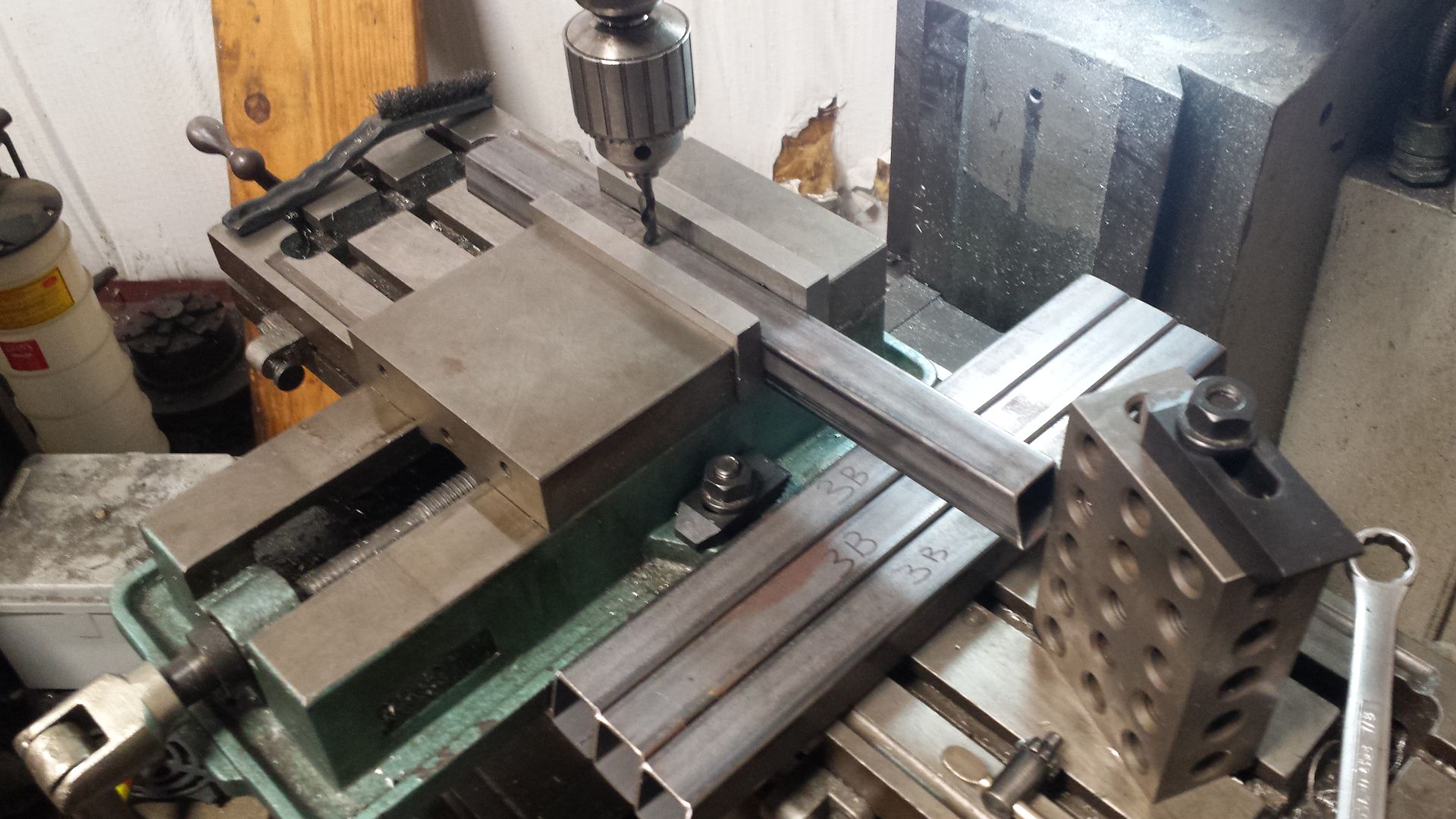
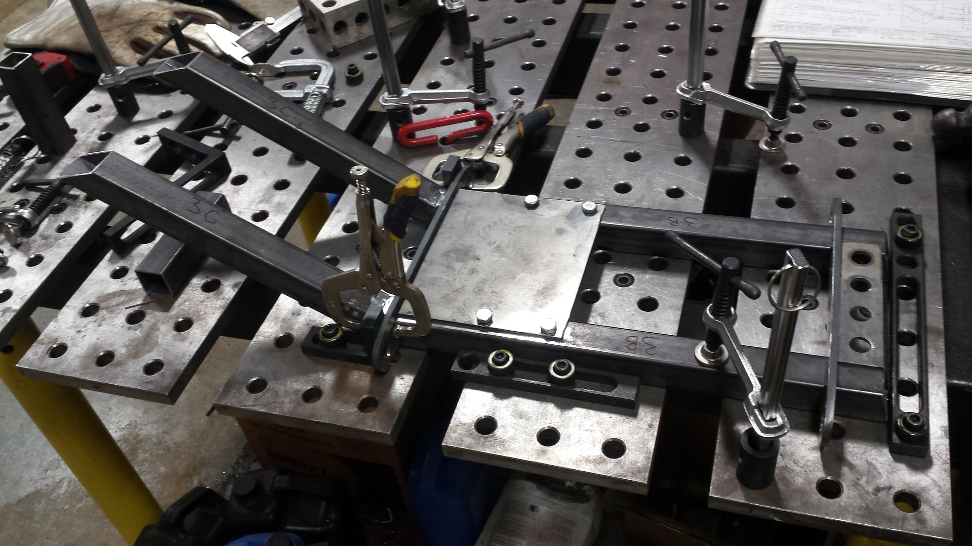
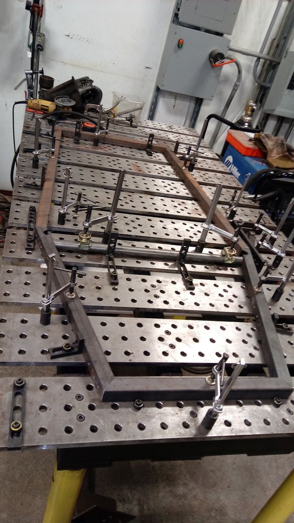
We managed to make some more progress on this. We received all the material for the nose so we started off cutting tubing. After cutting everything, we had to drill 4 holes in 4 pieces of tubing. They need to line up pretty well because there are plates with weld nuts that get slid inside of the tubing to provide mounting points. Our Bridgeport is a great way to do this.
Once the pieces were drill and welded the inserts in, we used a square to lay them out. You can see the directions book in the background suggesting to o do it this way. It sure makes it way easy and quick.
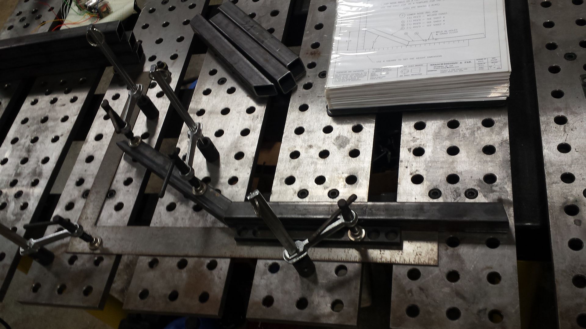
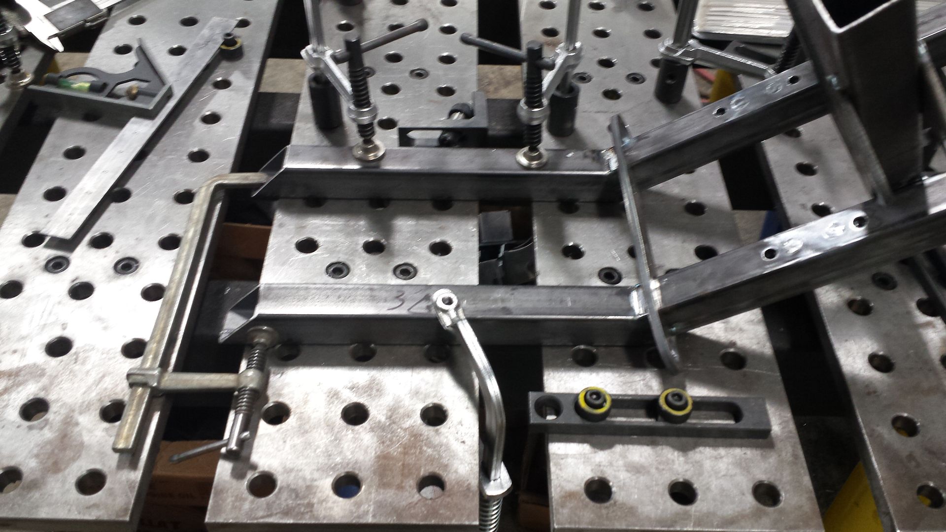
Another sub assembly needed to be made before we could put the nose together. The jig table makes this pretty easy. We had to do several so we put the 90s on to make it easy to load a second set of tubing without having to do a bunch of centering again.
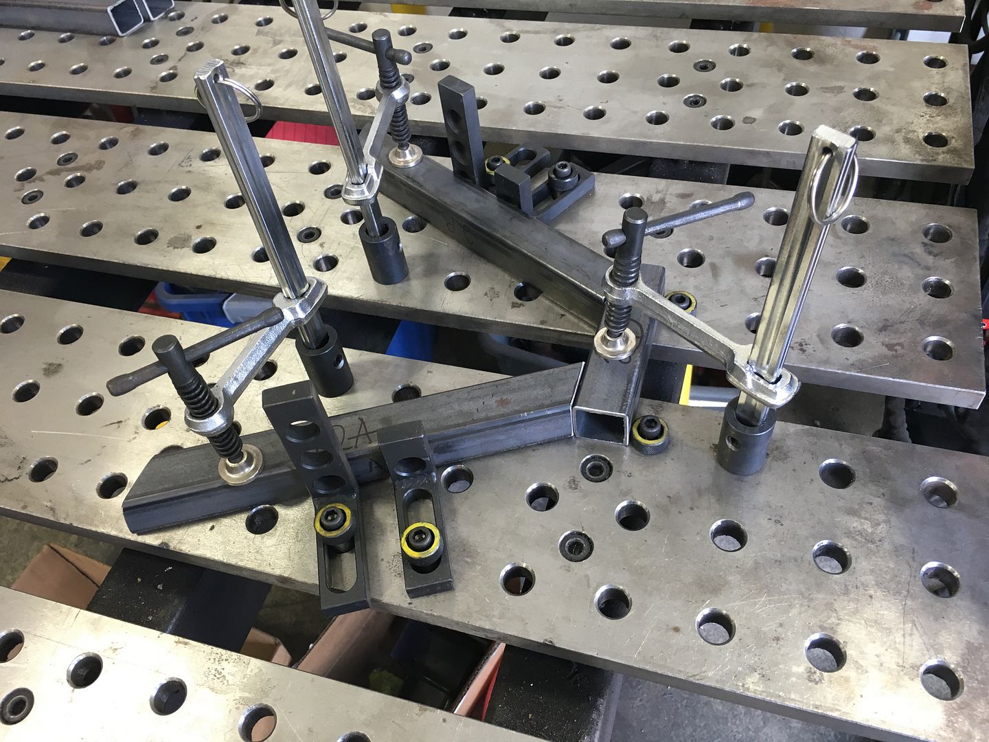
We put some tabs on them and called them done for now.
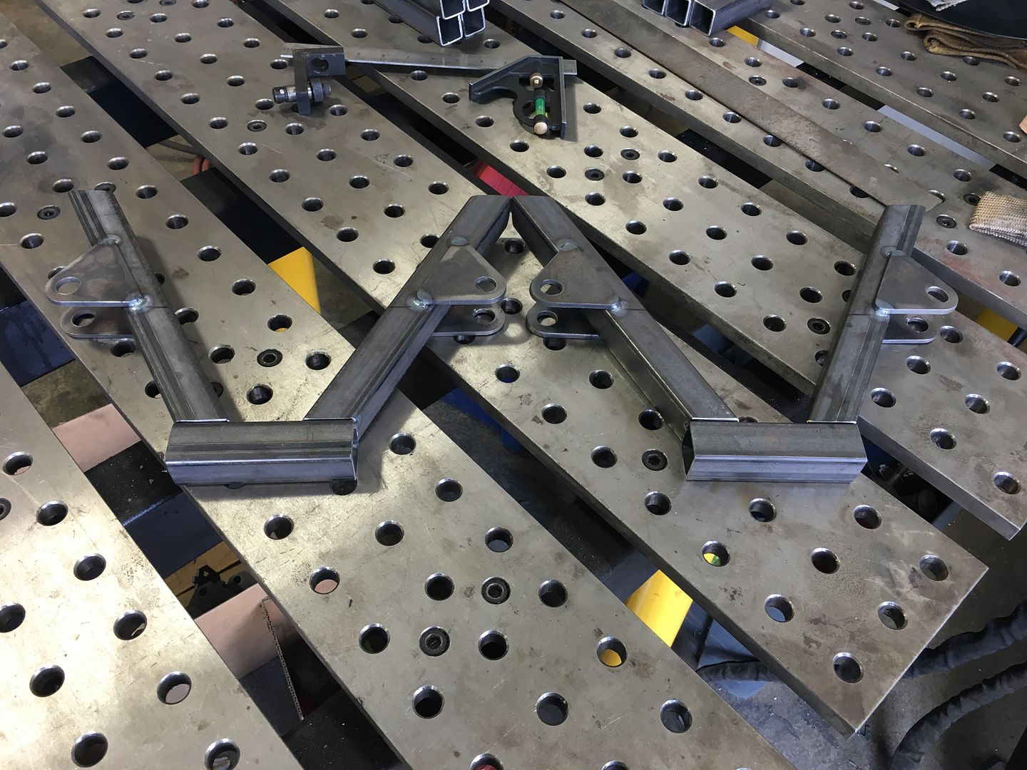
We cut out this alignment plate on our cnc plasma and bolted it to the inserts that we had welded in previously. This let us line up the sub assembly and the front lower control arm mount.
We rolled it up on it's front so we could put in the spacer tubes. It was close but not quite the correct dimensions we had to pull it in line.
We had to make one more sub assembly before we could put the nose together.
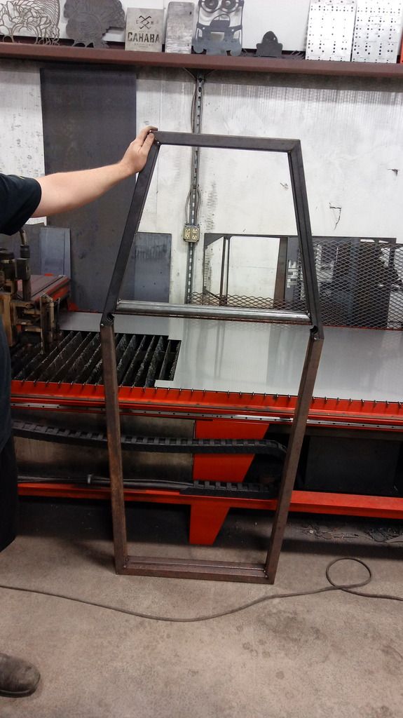
Here's one of the nose pieces with everything all tacked together.

Once the pieces were drill and welded the inserts in, we used a square to lay them out. You can see the directions book in the background suggesting to o do it this way. It sure makes it way easy and quick.

Another sub assembly needed to be made before we could put the nose together. The jig table makes this pretty easy. We had to do several so we put the 90s on to make it easy to load a second set of tubing without having to do a bunch of centering again.

We put some tabs on them and called them done for now.

We cut out this alignment plate on our cnc plasma and bolted it to the inserts that we had welded in previously. This let us line up the sub assembly and the front lower control arm mount.

We rolled it up on it's front so we could put in the spacer tubes. It was close but not quite the correct dimensions we had to pull it in line.

We had to make one more sub assembly before we could put the nose together.

Here's one of the nose pieces with everything all tacked together.

Rkbuell
Well-known member
Great craftsmanship, really very cool project. We need more up dates, please. Thanks
Winter in south Texas, we had nice cool mid 50's today, but hot as hell in summer.
Winter in south Texas, we had nice cool mid 50's today, but hot as hell in summer.
racer-john
Well-known member
Bump
Any progress?
Any progress?
Unfortunately, no major updates yet. I've been working on expanding my shop by almost 2000 sq feet and learning to setup, program, and use a CNC mill. We're kind of at a hold up until we get some DOM tubing anyway. I put in an order this week for what we needed.
We did get the nose pieces tacked onto the main portion of the lower frame.

We did get the nose pieces tacked onto the main portion of the lower frame.

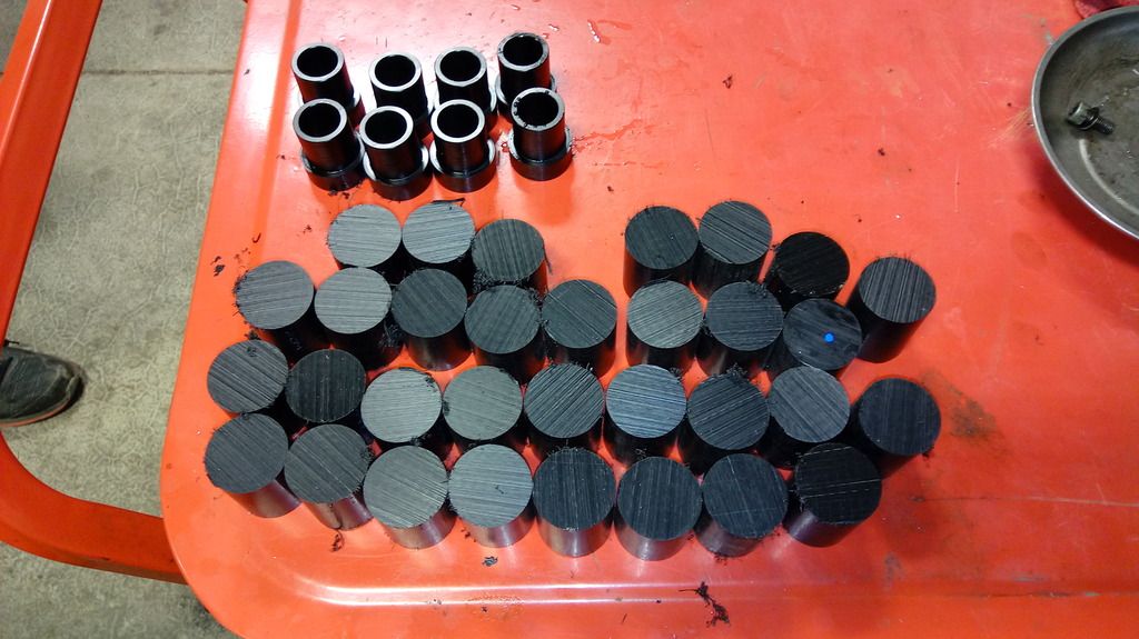
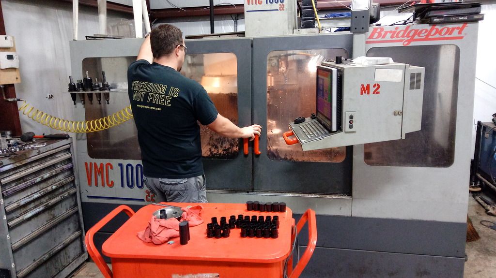
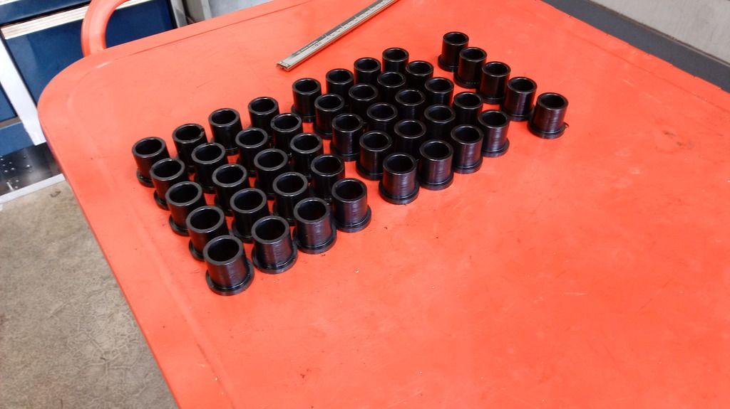
Time sure flys by sometimes. I've not been able to work on the buggy as much as I would like. I've had a lot of things that have taken up my time instead of working on my buggy project. We made all the bushings for the front and rear control arms the other day. We decided to give a try making them in our newly accquired VMC. Getting the VMC delivered, setup, and tooled up is one of the things that has taken up my buggy project time. It's also a steep learning curve to go from manual machinery to running a cnc mill.
We cut all the bar stock to length. We cut the piece a bit longer as to have enough to hold onto. The excess was to be machined off afterwards in the second operation.
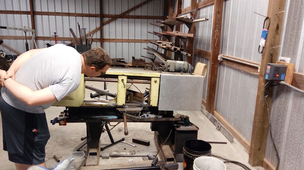
Here's Jason, my BIL who is building the second buggy, running bushings in our VMC.
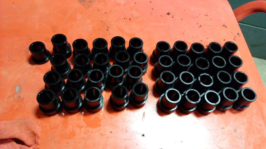
Two full sets of bushings done with the first operation.
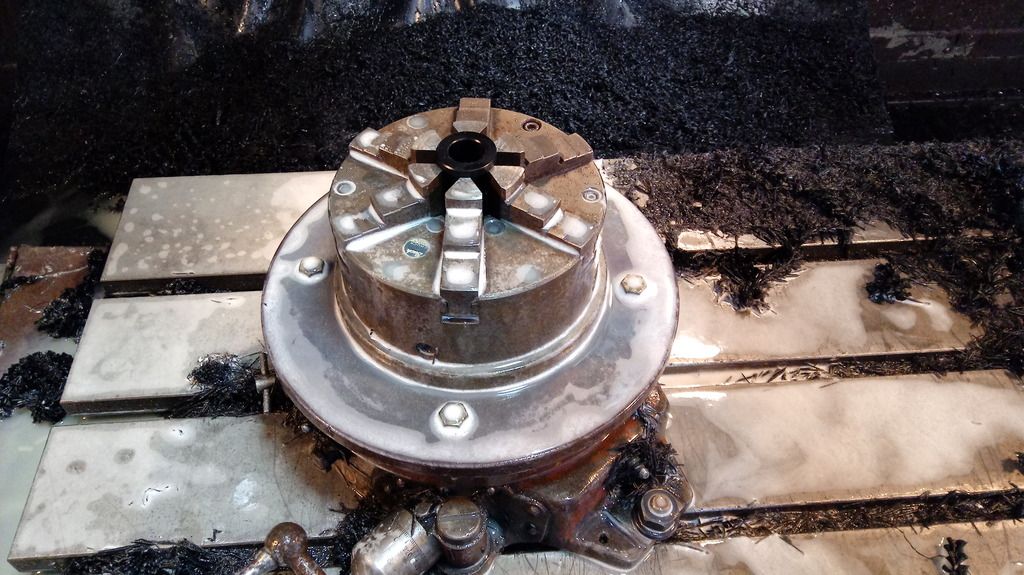
On to the second operation. This was just facing the shoulder to length and chamfering the holes.
Here's the full sets all done with 5 spares.
We'll be back to bending tube and building the frames shortly.
We cut all the bar stock to length. We cut the piece a bit longer as to have enough to hold onto. The excess was to be machined off afterwards in the second operation.

Here's Jason, my BIL who is building the second buggy, running bushings in our VMC.

Two full sets of bushings done with the first operation.

On to the second operation. This was just facing the shoulder to length and chamfering the holes.

Here's the full sets all done with 5 spares.

We'll be back to bending tube and building the frames shortly.
Last edited:
We started off this round cutting some more tubing.
Sometimes things just don't go as planned.
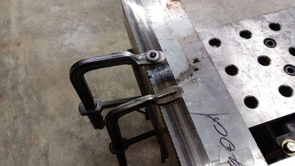
I of course forgot to order a spare blade last time I ordered stuff like this. Time to try my hand at welding it up. I figured getting it lined up good would be the first step.
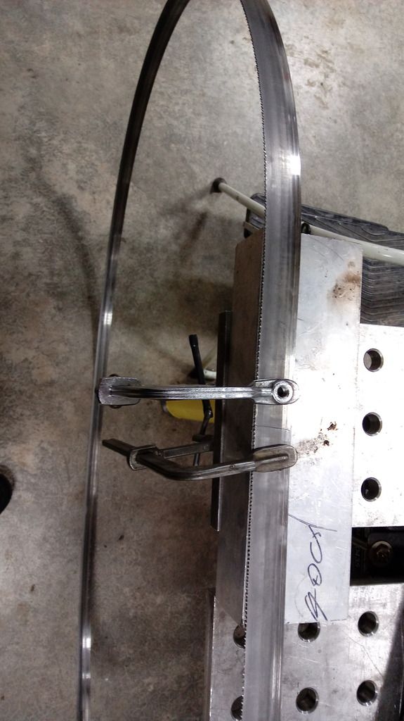
These are pretty tedious to weld. I welded it on both sides then ground it down. I heated it up cherry red with a torch to try to anneal it. It worked out and is still on my saw a week later.
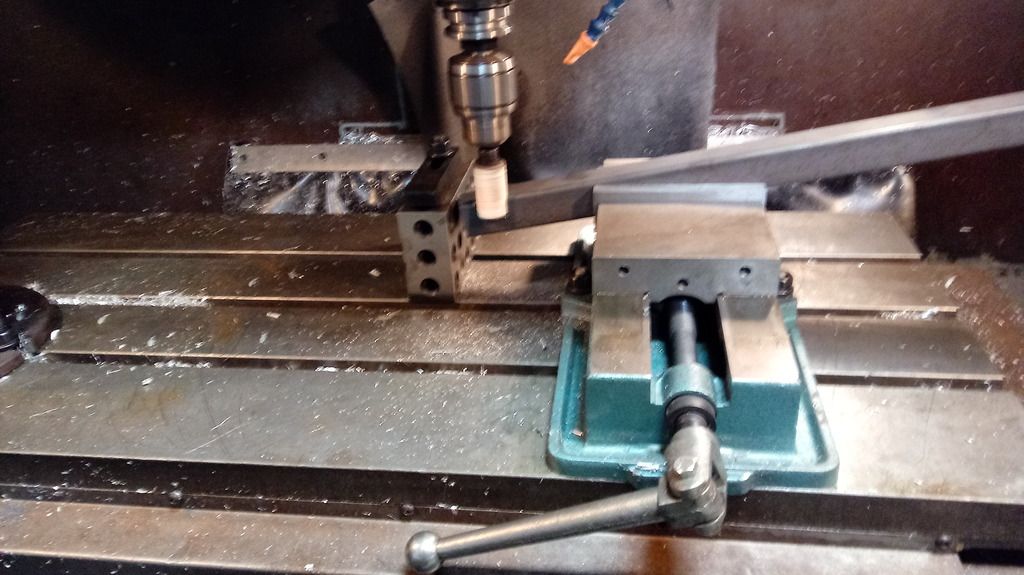
There's some odd notches in this part of the frame for the tubing to go through. We set them up in the mill to notch. Keep in mind since we are building two buggies that setup time isn't as much of a big deal if it means getting through the overall parts quicker. It's also hard to argue with the accuracy of using a mill. I didn't take any more pictures of stuff done in the mill but we also used it to drill all the holes in the tubes(10 ea). I'm getting fairly proficient at putting together a quick program to do things like this. I like being able to load a part in the machine and press the go button. We also made the tap plates for the motor mounts in the mill.
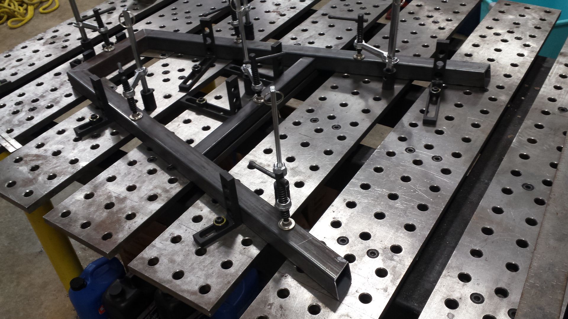
Laying out the next frame layer on the jig table.
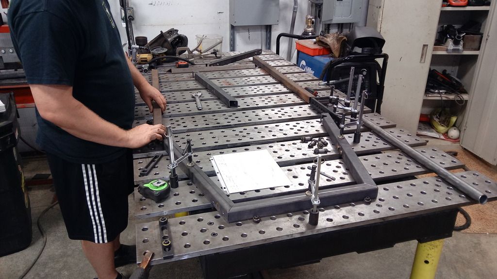
Here it is all jigged up.
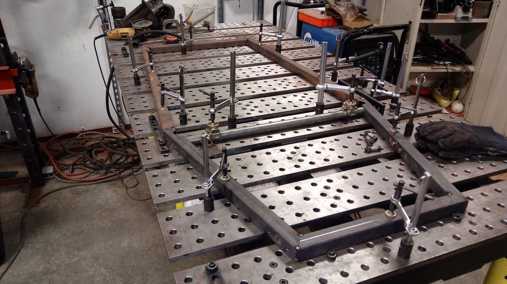
Jason holding up the two frame sections.

Sometimes things just don't go as planned.

I of course forgot to order a spare blade last time I ordered stuff like this. Time to try my hand at welding it up. I figured getting it lined up good would be the first step.

These are pretty tedious to weld. I welded it on both sides then ground it down. I heated it up cherry red with a torch to try to anneal it. It worked out and is still on my saw a week later.

There's some odd notches in this part of the frame for the tubing to go through. We set them up in the mill to notch. Keep in mind since we are building two buggies that setup time isn't as much of a big deal if it means getting through the overall parts quicker. It's also hard to argue with the accuracy of using a mill. I didn't take any more pictures of stuff done in the mill but we also used it to drill all the holes in the tubes(10 ea). I'm getting fairly proficient at putting together a quick program to do things like this. I like being able to load a part in the machine and press the go button. We also made the tap plates for the motor mounts in the mill.

Laying out the next frame layer on the jig table.

Here it is all jigged up.


Jason holding up the two frame sections.

Last edited:
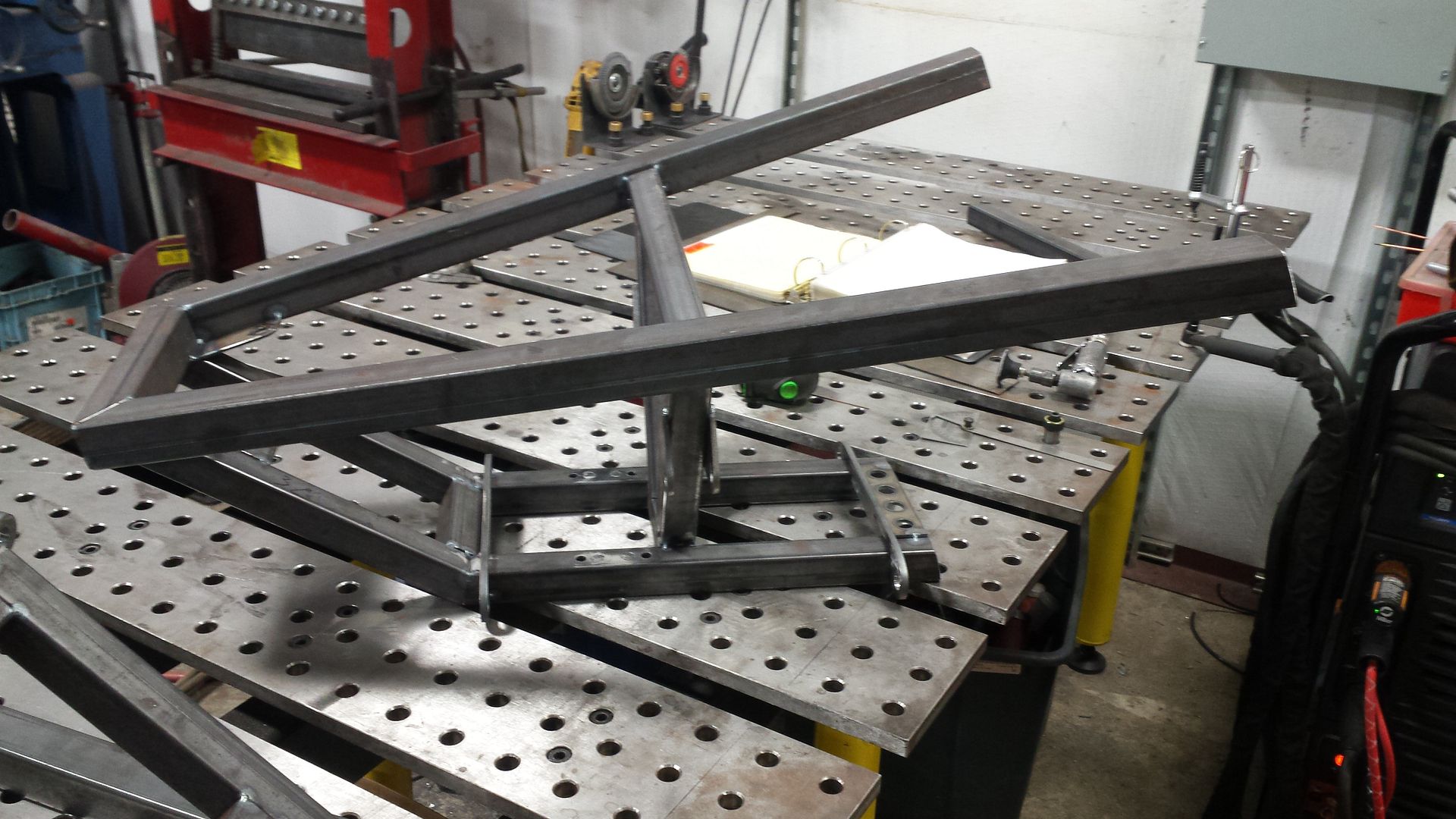
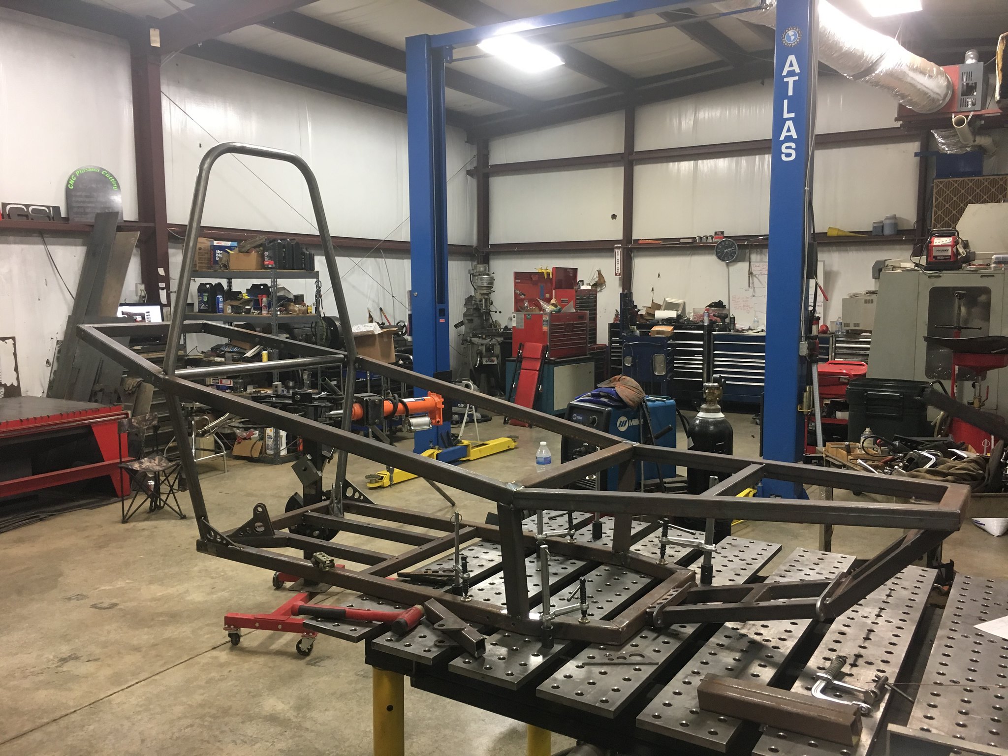
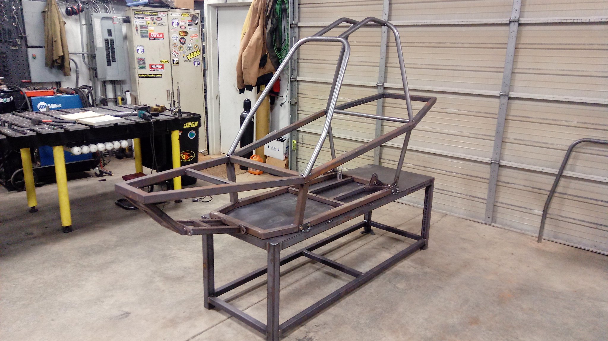
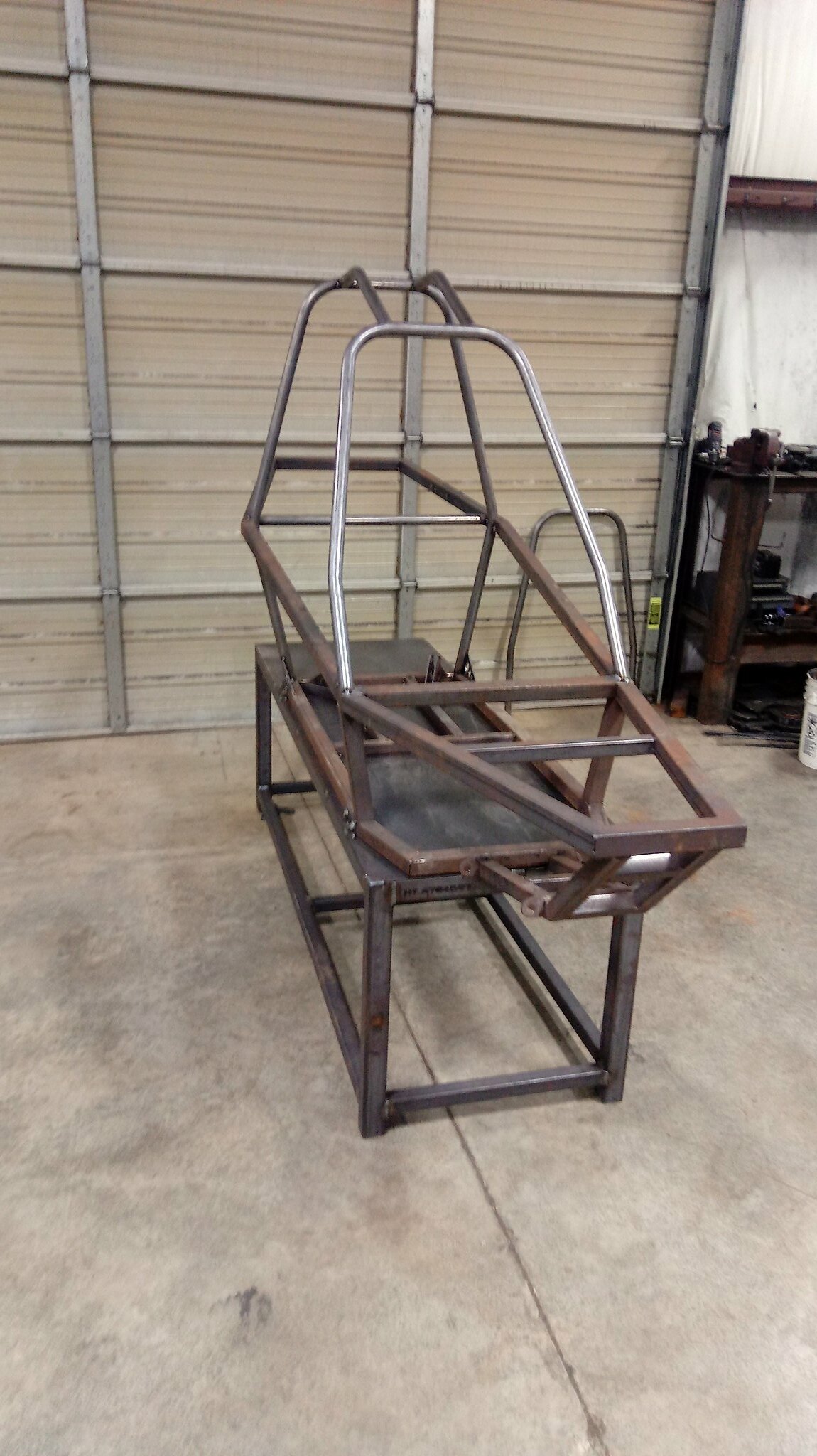
It's been to long. We got back to working on the buggies the other day. I had taken a while off due to going to ride in Colorado for two weeks and having to get ready. We made some progress on the frames. They are starting to look like a buggy. Unfortunately all my previous pictures were on photobucket.
 IMG_0938 by Griffin93, on Flickr
 IMG_0936 by Griffin93, on Flickr
 IMG_0935 by Griffin93, on Flickr
 IMG_0933 by Griffin93, on Flickr
IMG_0938 by Griffin93, on Flickr
IMG_0936 by Griffin93, on Flickr
IMG_0935 by Griffin93, on Flickr
IMG_0933 by Griffin93, on Flickr
Last edited:
wretched73
Well-known member
Looks awesome, I'm interested in doing a souped up pilot myself.
Very interested how this continues to come together!
Very interested how this continues to come together!
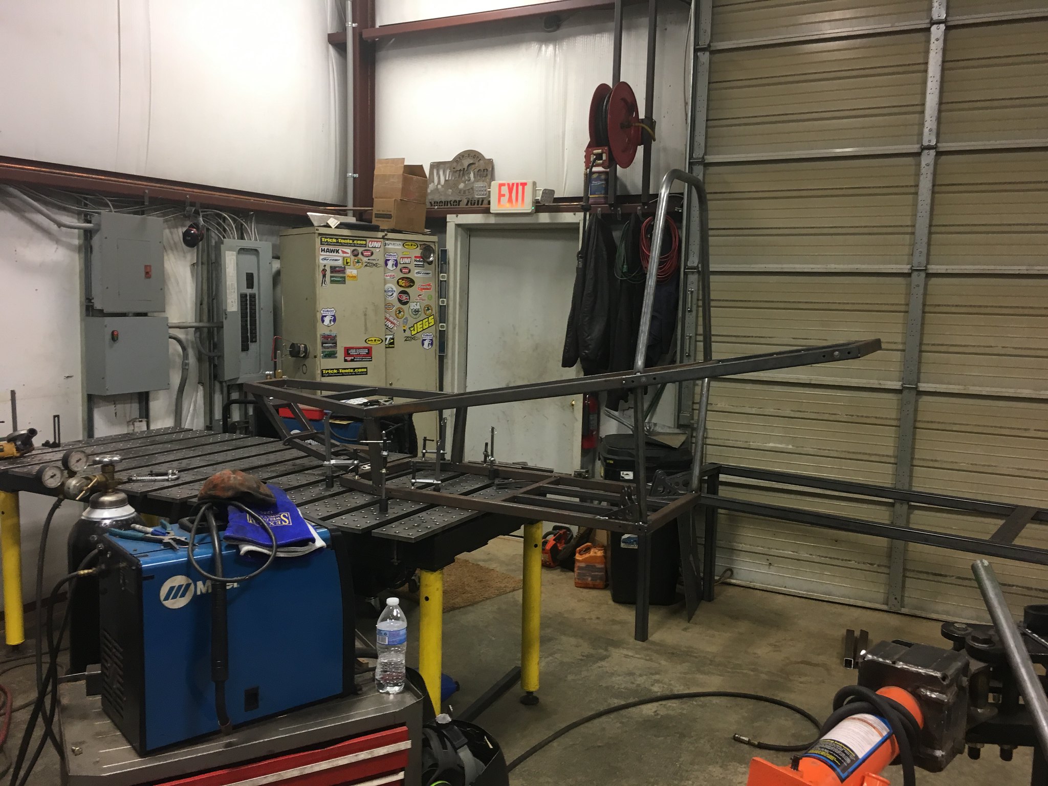
The chassis are starting to get a bit large to drag in and out of the shop by hand. I would rather bring them in on forks when I have a bit of time to work on them. I decided the best way to do something about that would be to build a couple of custom stands to hold them. I'm going to bolt them to the chassis with some tabs that will line up with the mounts for the nerf bars.
First, we cut all the tubing to length and jigged it up on the table.
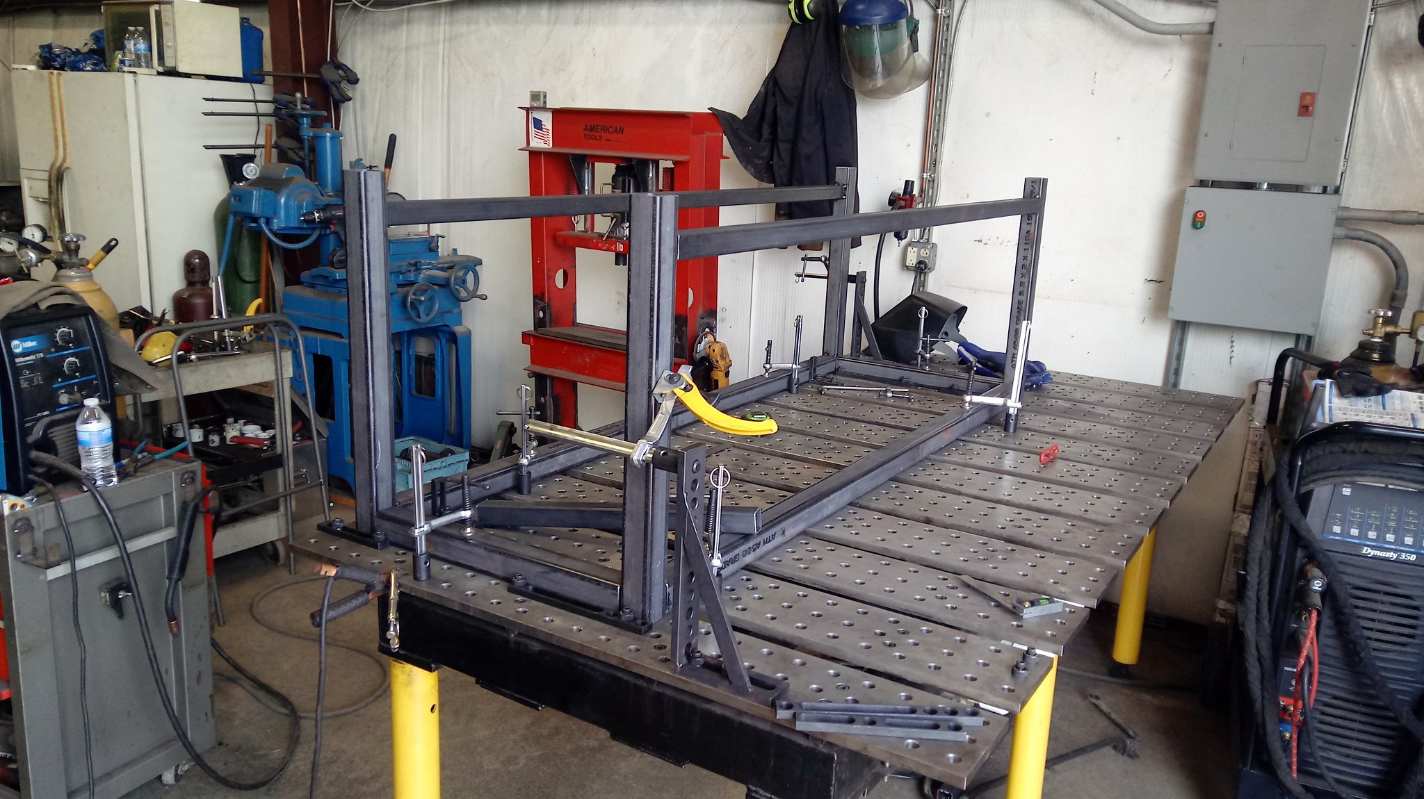
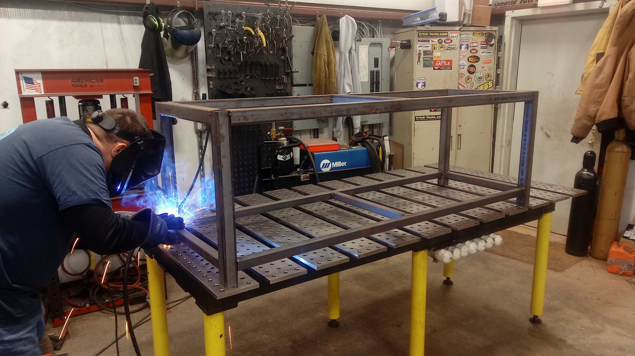
Then, we welded it all out and cut a top from 1/8" plate. After we're done building the buggies I plan to add extensions to the leg to use these as work benches.

First, we cut all the tubing to length and jigged it up on the table.
Then, we welded it all out and cut a top from 1/8" plate. After we're done building the buggies I plan to add extensions to the leg to use these as work benches.
skrap metal
Well-known member
very nice
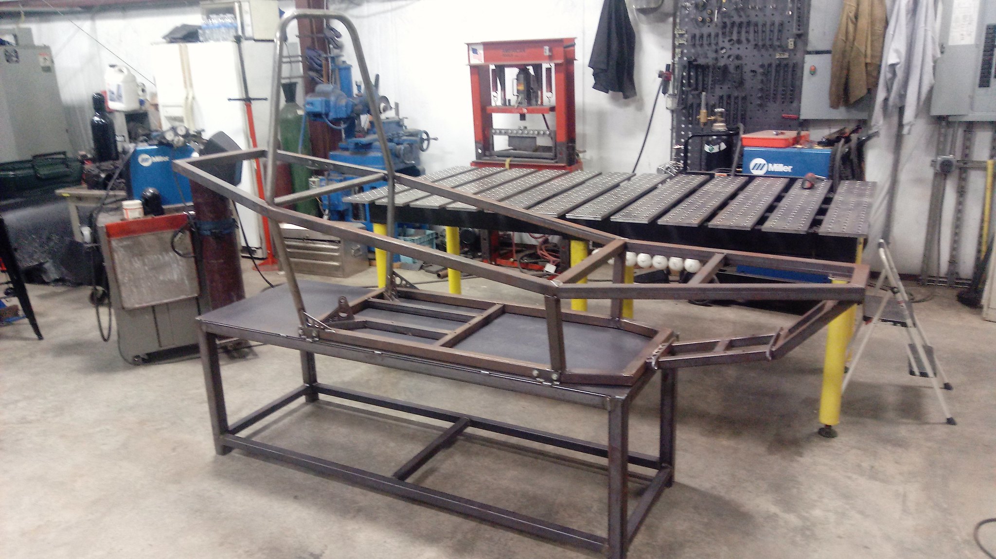
We got the second table welded up. Jason got plenty of welding practice doing that one.
 2018-01-07_10-58-06 by Griffin93, on Flickr
We cut some tabs out on our plasma table and got the chassis mounted to the table.
 2018-01-19_07-32-28 by Griffin93, on Flickr
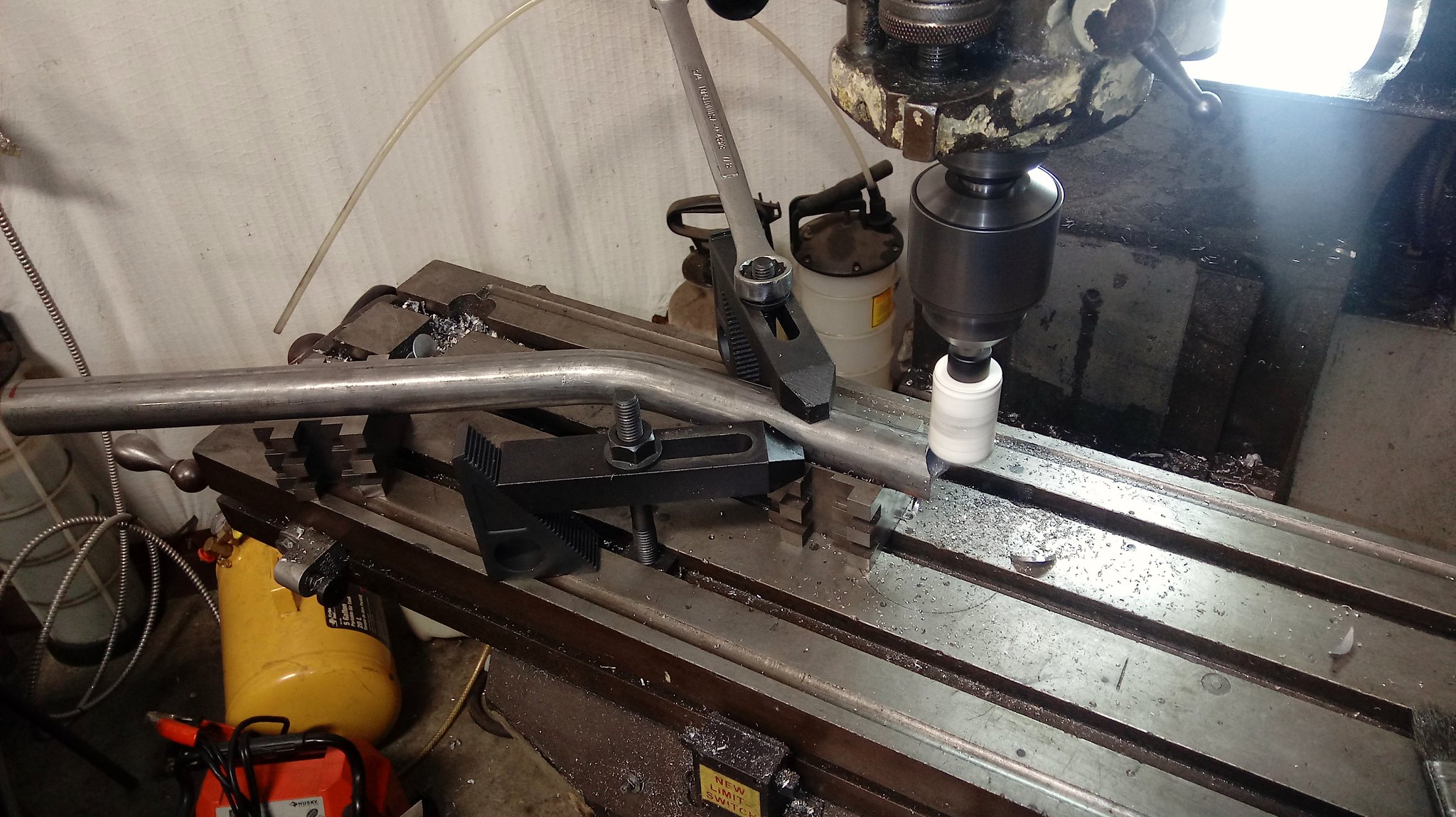
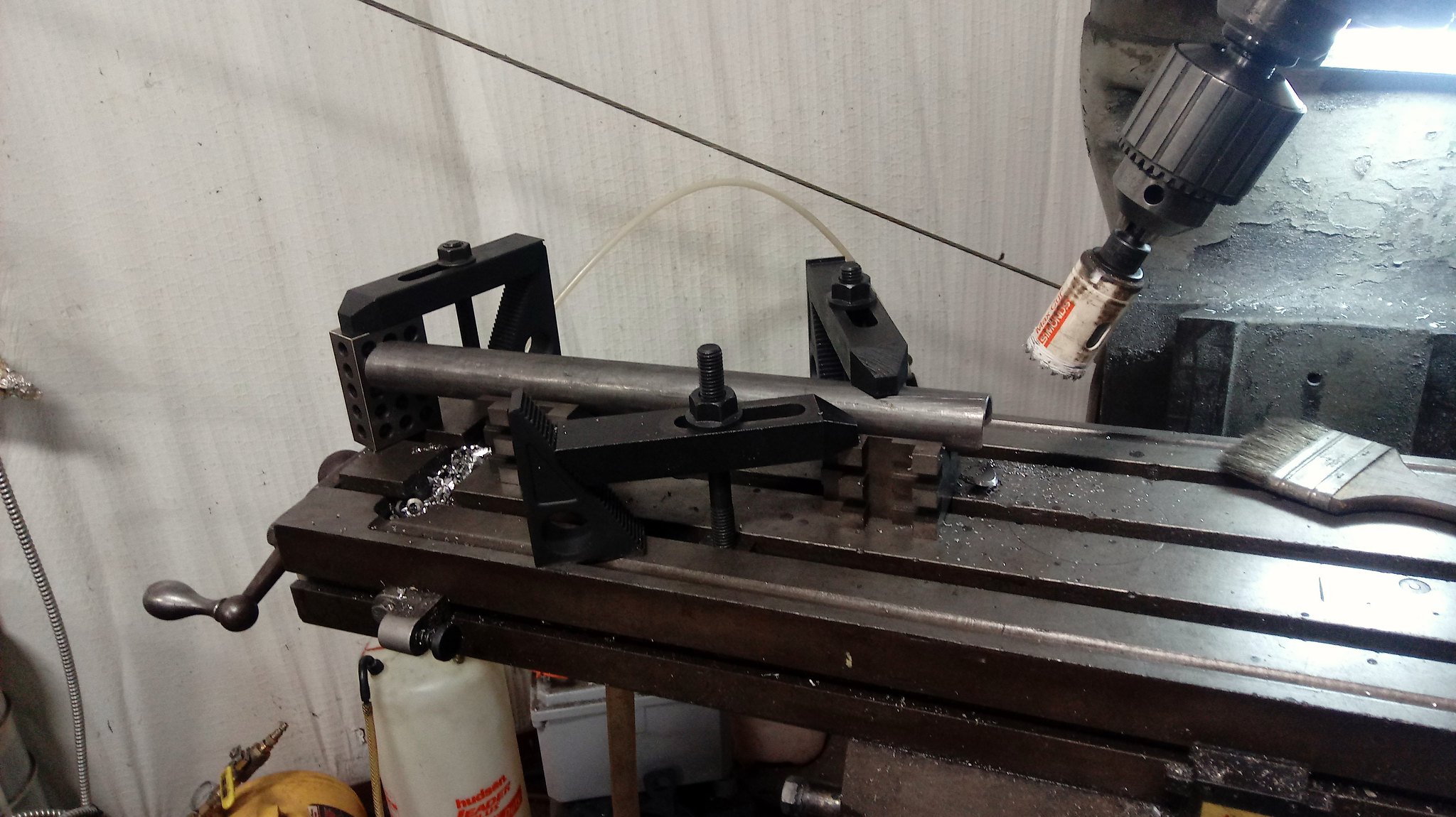
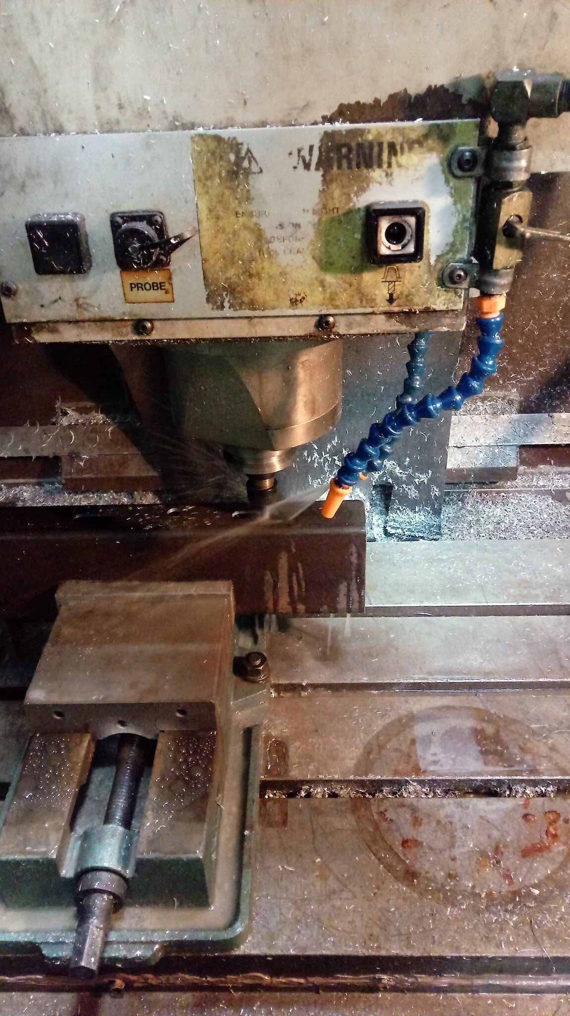
We started bending and notching tubing. I've been notching in my bridgeport mill. I had a notcher but it broke. I haven't been real motivated to buy another one when the bridgeport is just about as quick and seems to do a better job. It will also notch anywhere in a bend.
 2018-01-16_07-23-14 by Griffin93, on Flickr
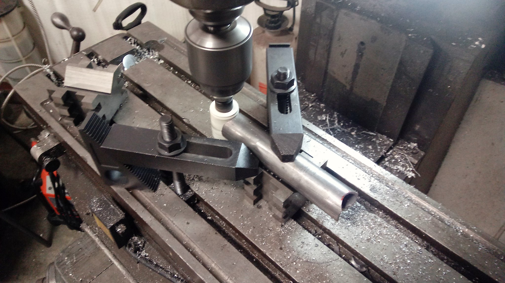
It's really handy for notches like this on short piece that are hard to get a plane of bend bracket on. No problem with lining up their rotation.
 2018-01-16_07-23-54 by Griffin93, on Flickr
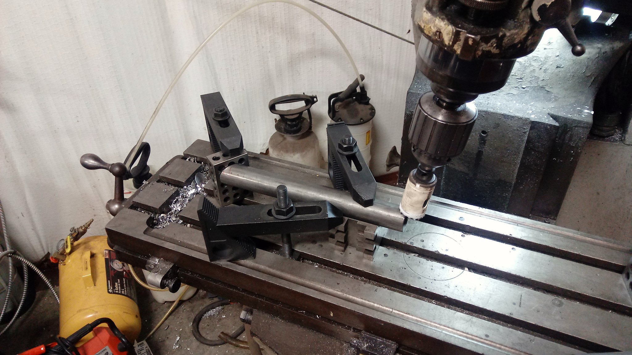
It's also really easy to put a 1-2-3 block on the table to line up multiple pieces. Keep in mind we're building two of these at once. It's nice when everything like this fits together nicely with no grinding at all.
 2018-01-16_07-24-16 by Griffin93, on Flickr
Angles are also no problem. Just swing the head. It's 4 bolts to undo.
 2018-01-16_07-24-37 by Griffin93, on Flickr
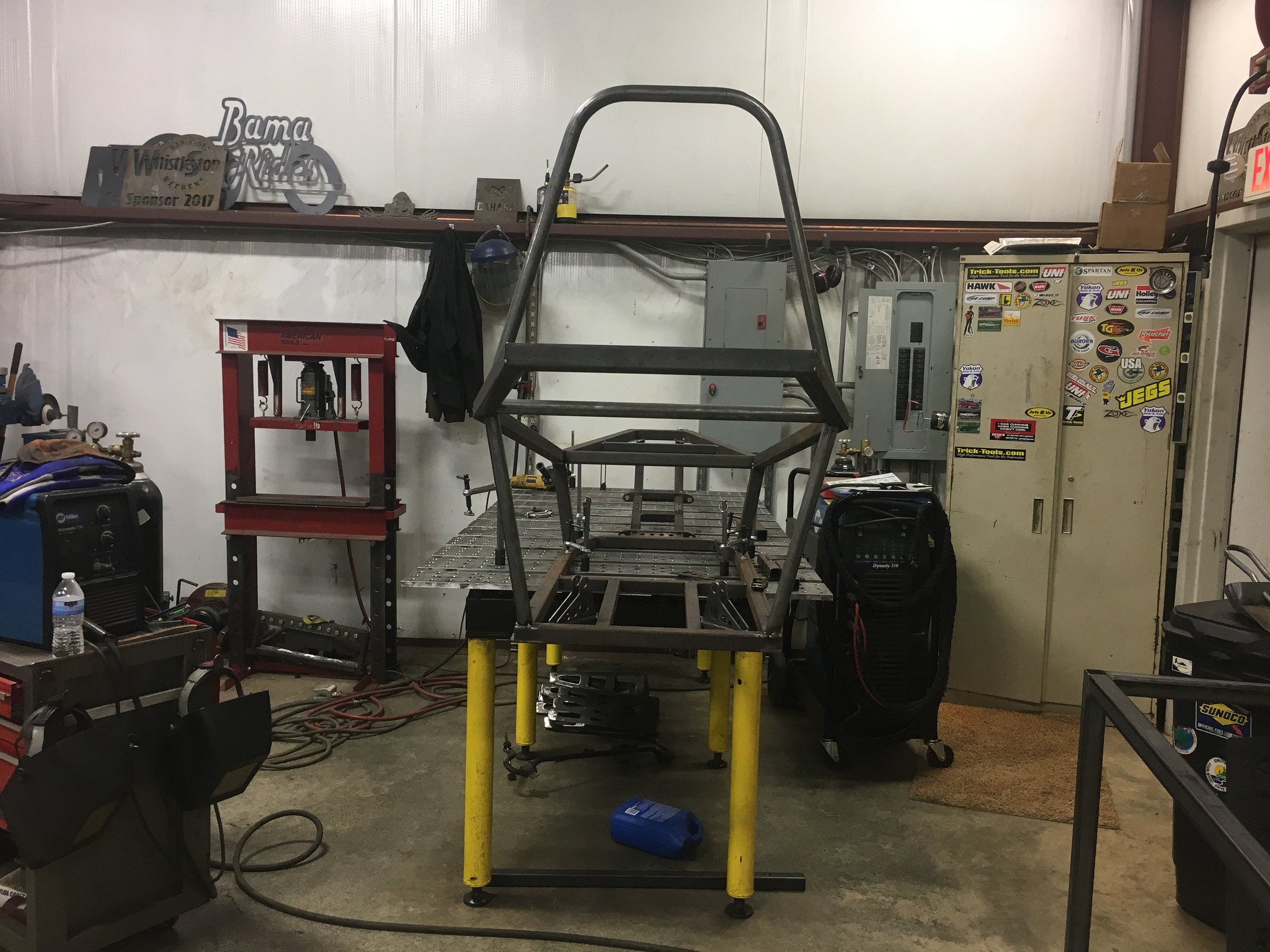
We got the front hoop and top bars stuck on the chassis.
 2018-01-16_07-25-10 by Griffin93, on Flickr
It's starting to look like something.
 2018-01-16_07-25-27 by Griffin93, on Flickr
2018-01-07_10-58-06 by Griffin93, on FlickrWe cut some tabs out on our plasma table and got the chassis mounted to the table.
2018-01-19_07-32-28 by Griffin93, on FlickrWe started bending and notching tubing. I've been notching in my bridgeport mill. I had a notcher but it broke. I haven't been real motivated to buy another one when the bridgeport is just about as quick and seems to do a better job. It will also notch anywhere in a bend.
2018-01-16_07-23-14 by Griffin93, on FlickrIt's really handy for notches like this on short piece that are hard to get a plane of bend bracket on. No problem with lining up their rotation.
2018-01-16_07-23-54 by Griffin93, on FlickrIt's also really easy to put a 1-2-3 block on the table to line up multiple pieces. Keep in mind we're building two of these at once. It's nice when everything like this fits together nicely with no grinding at all.
2018-01-16_07-24-16 by Griffin93, on FlickrAngles are also no problem. Just swing the head. It's 4 bolts to undo.
2018-01-16_07-24-37 by Griffin93, on FlickrWe got the front hoop and top bars stuck on the chassis.
2018-01-16_07-25-10 by Griffin93, on FlickrIt's starting to look like something.
2018-01-16_07-25-27 by Griffin93, on FlickrBoosted1
Well-known member
Very cool project.
It's been way to long but we managed to get some buggy stuff worked on the other day. I'm self employed so sometime I really don't have time to do anything. I own two different businesses and this year they have both grown a lot. Hopefully as this trend continues, I'll be able to find some more help and have more time for myself again.
We used my cnc mill to make the piece that the chain adjuster slides in. I actually cut the 1/2" slots with a 1/4" end mill. I was able to program it to helic into the material then walk around the slots.
 2018-09-22_08-37-18 by Griffin93, on Flickr
We also made all the rear arm spacers on the lathe. I forgot to take any pictures. Once we had those and the chain adjuster tube, we assembled the rear carrier.
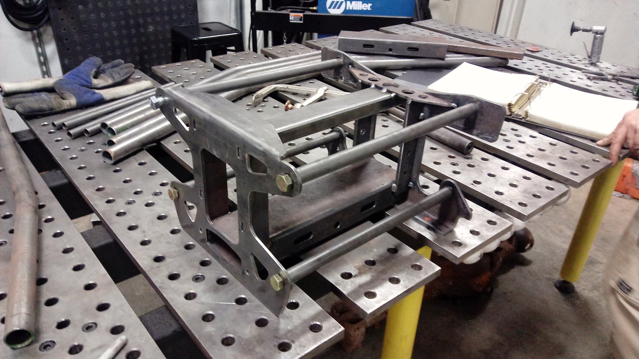 2018-09-22_08-37-38 by Griffin93, on Flickr
We used my cnc mill to make the piece that the chain adjuster slides in. I actually cut the 1/2" slots with a 1/4" end mill. I was able to program it to helic into the material then walk around the slots.
2018-09-22_08-37-18 by Griffin93, on FlickrWe also made all the rear arm spacers on the lathe. I forgot to take any pictures. Once we had those and the chain adjuster tube, we assembled the rear carrier.
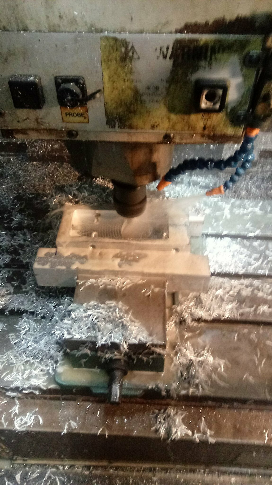
2018-09-22_08-37-38 by Griffin93, on FlickrI'm really trying to find time to work on this thing. We found a bit Sunday afternoon. We decided to deviate from the plans slightly. The chain adjuster piece is made of three pieces of plate and one piece of tubing. We decided to machine it out of a piece of aluminum instead. Like any good project, you have to make something before you can make the part for your project. We had to machine some longer soft jaws to be able to clamp this part in the vise as the pocket in the middle is roughly 7" long so I didn't want 6" vise jaws squeezing it. We machined them out of some 2" bar I had laying around. I slotted the mount holes so they can be turned upside down to be able to get more uses out of them.
We started by machining the outsides to the desired dimensions. Next, we drilled and tapped 5 holes around the perimeter. I didn't take any pictures of this going on unfortunately. We set the part down into the vise jaws and started removing material out of a large pocket.
 2018-10-28_10-15-11 by Griffin93, on Flickr
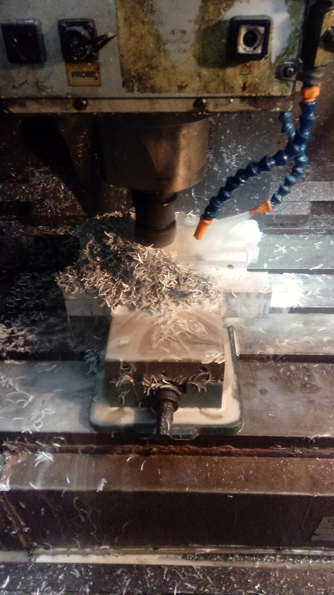
I started pushing the feeds and speeds as I was using a 3 ft carbide end mill. I ended up at 4000 rpm and 43.2 IPM. It took about 7 minutes to pocket this out all the way through a piece of 1" plate. It really started piling up the chips. I ended up using compressed air blowing out of the front coolant pipe to move the chips out of the cutting area.
 2018-10-28_10-14-43 by Griffin93, on Flickr
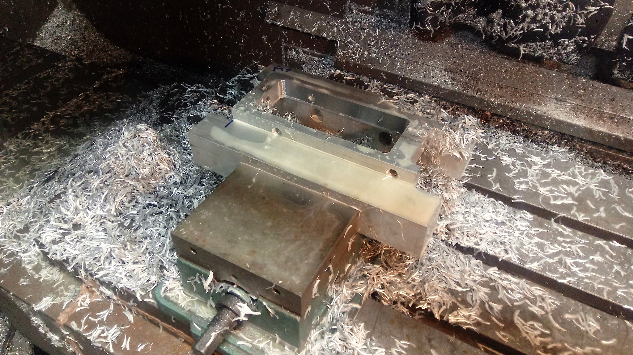
You can really see the soft jaws holding the part here. I really didn't want the part to get loose or collapse from regular jaws so this worked very well.
 2018-10-28_10-15-42 by Griffin93, on Flickr
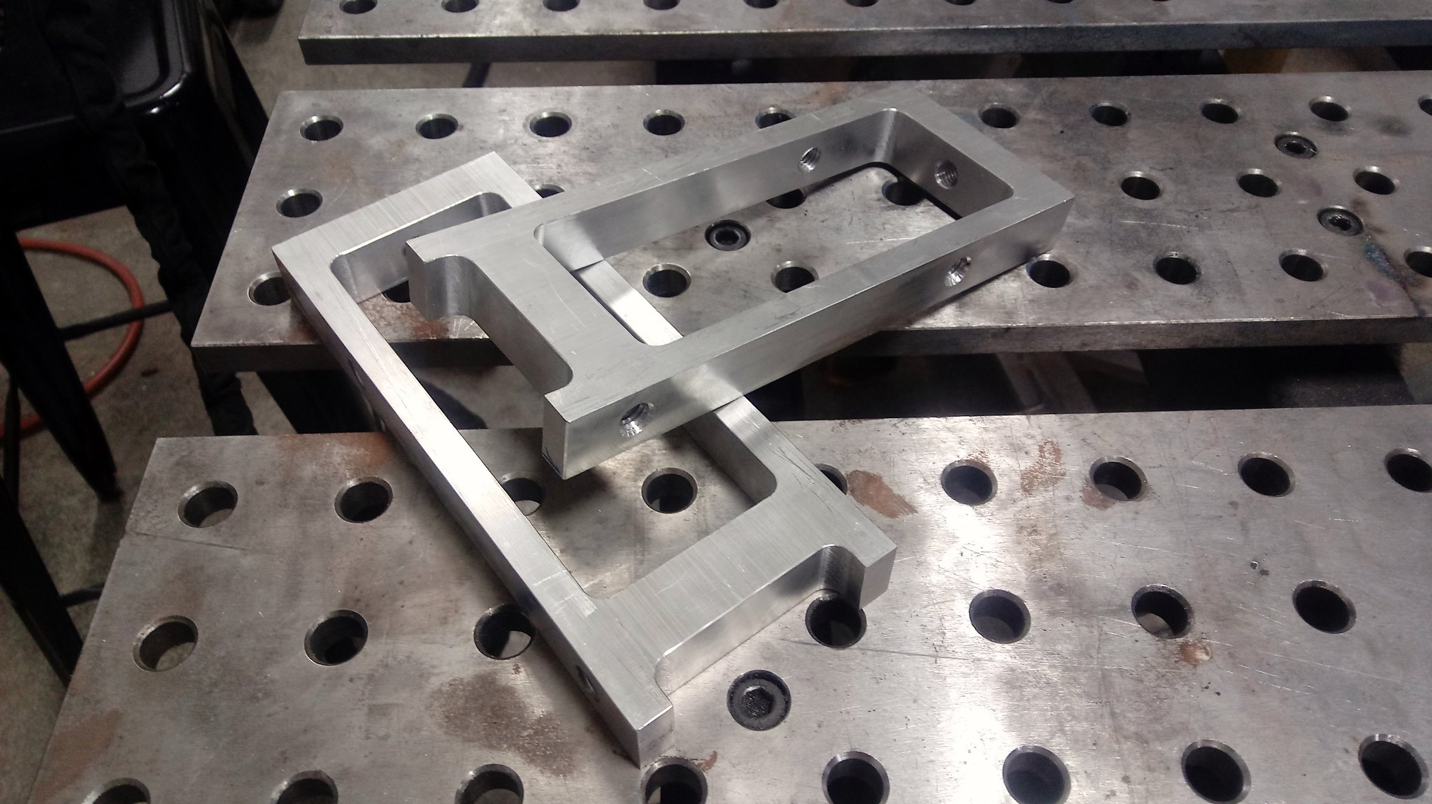
Here they are all cleaned up and deburred.
 2018-10-28_10-15-56 by Griffin93, on Flickr
We started by machining the outsides to the desired dimensions. Next, we drilled and tapped 5 holes around the perimeter. I didn't take any pictures of this going on unfortunately. We set the part down into the vise jaws and started removing material out of a large pocket.
2018-10-28_10-15-11 by Griffin93, on FlickrI started pushing the feeds and speeds as I was using a 3 ft carbide end mill. I ended up at 4000 rpm and 43.2 IPM. It took about 7 minutes to pocket this out all the way through a piece of 1" plate. It really started piling up the chips. I ended up using compressed air blowing out of the front coolant pipe to move the chips out of the cutting area.
2018-10-28_10-14-43 by Griffin93, on FlickrYou can really see the soft jaws holding the part here. I really didn't want the part to get loose or collapse from regular jaws so this worked very well.
2018-10-28_10-15-42 by Griffin93, on FlickrHere they are all cleaned up and deburred.
2018-10-28_10-15-56 by Griffin93, on FlickrTurned some bushing in our new TL2 Haas Lathe other day for the buggy. These go on the front control arms.
 2019-01-01_03-54-23 by Griffin93, on Flickr
2019-01-01_03-54-23 by Griffin93, on Flickr
