To avoid these ads, REGISTER NOW!

Automotive spot welding

RickP330

Well-known member
Joined
Apr 12, 2007
Messages
831
Location
Middle Island, NY
Hello gang!

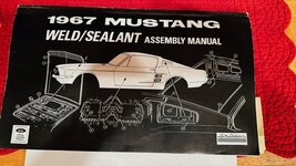
So I have decided that after I finish my current project in a year from now - I am going to start a new automotive project. In this project I’ll be trying to recreate factory assembly methods. This means I’ll be employing a lot of spot welding. It may be impossible to do this to 100% fidelity, but where reasonable I want to use this method. All I have ever done prior was MIG, TIG and Brazing. So, I spent the last 6 months or so studying spot welding and stalking used machines on Ebay.

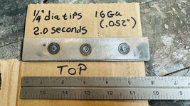
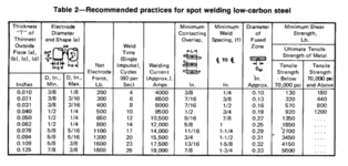
I wanted to make sure I could find a unit that was powerful enough for structural welds and wouldn’t melt down halfway through the project. So, a 220-volt 35-amp welder seemed like the biggest I could power from a home shop. The next size larger is 90 amp and I only have a 100-amp panel. Using some spot welding references, I see that a 220V x 35-amp supply will reasonably get you decent current at the weld tips suitable for up to 3/16” steel. The only other item is how to control it, and weld time seems to be the only choice, so I looked for a unit with a timer for consistent welds. (There are no current controls and you can’t change the tip voltage…).

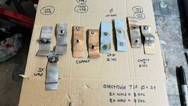
The other part to this problem is how am I going to weld prep the seams? There are a plethora of options and very little solid information on what works best. There is traditional Zinc weld through, Copper with Zinc weld through and just pure Copper weld through. The Zinc is supposed to be a sacrificial element in the seam, but in terms of welding it is a contaminant and must be removed from the weld area before. This is simple if you are MIG plug welding, but a major PITA for spot welding.

Additionally, 3M has a structural bonding adhesive that they market to be used in conjunction with spot welding. My head was spinning. What to do? Well really the only way to really know is to actually test them all and choose. Plus, I am not even convinced that the welder would be sufficient without any prep. I was ready to enter into test mode.

I noticed that spot welders seemed to be selling around $800 used on eBay. Occasionally, I saw a few slip through that ought to be snipe-able. I finally did enough research - it was time to act if I ever was going to. I found I great candidate and was able to secure a deal with the seller for $400. On the plus side it came with a rotating support fixture you could hold it in with a tool balance, but no returns or guarantee it would actually work. Well, it was a gamble, and the tips and tongs were new which run around $275 so there should be enough value in parts if it falls through.

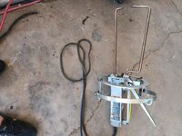
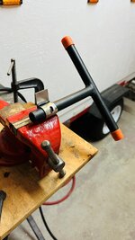
I bought a Miller LMSW-52T 220Volt 35-amp spot welder with timer. Well, it did need a fair amount of work to make it useable:

  • I installed a 220V 35-amp outlet in a convenient location in the middle of the shop.
  • The jaws were taken apart and put back together backwards, that was a head scratcher, I also had to buy new lock nuts for it. The clamping mechanism was totally wacked, cleaned it all up and put some lube on it.
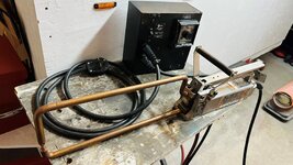
  • I took off the counterbalance support and made a handle from some Stainless and G-10 rod (Nonconductive).
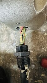
  • It didn’t work right and noticed the16 ga 4 conductor SJ cord to the rear cap was worn through and grounding, of course I upgraded to 14 ga and replaced both cables and cord grips.
  • After that it didn’t work at all, and I was really pulling my hair out. Turns out the braided connectors were shot and – of course – installed backwards (it was installed in a Z shape, should be U shape). I also changed the DPDT switch out of desperation first.
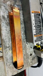
  • Now it had been totally disassembled, I noticed the secondary coil (basically a giant copper U shaped bar) was a little twisted and uncomfortably close to grounding on the case – I straightened it out.

So, it took a little time and a lot of head scratching, but I got it sorted out and believe it is working as it should be now. Getting decent welds. I’ll Stop here and post a few pics. (Unit as bought with halo, damaged 16 conductor, spent tong brads, secondary coil copper bar, and the completely revamped welder ready to roll.)

Rick
 

Attachments

  • SpotWelder_3.jpeg
    SpotWelder_3.jpeg
    109.5 KB · Views: 110
  • SpotWelder_9.jpg
    SpotWelder_9.jpg
    528.9 KB · Views: 96
  • SpotWelder_16.jpg
    SpotWelder_16.jpg
    805.1 KB · Views: 93
  • SpotWelder_18.jpg
    SpotWelder_18.jpg
    1.1 MB · Views: 99
  • SpotWeld_29.jpg
    SpotWeld_29.jpg
    672.1 KB · Views: 110
To avoid these ads, REGISTER NOW!
OP
R

RickP330

Well-known member
Joined
Apr 12, 2007
Messages
831
Location
Middle Island, NY
What's your next project?
Hey 930,
I wanted to avoid making this thread about the project - but you are absolutely right. Some context is required.

The project is a 1967 Mustang. I'll be working closely with the "Weld / Sealant assembly manual".

Now that I have selected my welder and apparently have it working appropriately, I need to make sure it can duplicate factory style welds. The manual calls out for Class 1, 2 and 3 spot welds - but goes into no further detail and I've hit a dead end. Class 3 appears to be structural welds as they are called out in 98% of the manual (Frame rails, torque boxes and rocker panels...).

Spot welding literature indicate testing a weld "nugget" diameter based on material thickness and a peel test. So, time to cut out some weld coupons, weld them and test them. First, I tried pulling them apart with vise grips to no avail - so far so good, I think? Then I got out the air hammer and some ripped out, some split. I couldn't get a consistent parting, and the parts got mutilated in the process. I saw a video where a Honda specification "twisted" the spot welds. I tried that - but they all failed (No nugget). but it's clear that specification was for a different process and used a different style of spot welder. Finally, I stumbled upon a peel test where they used a tube with a slot and a T handle - of course. That's how to do it. So, I built a tool of my own. Indeed - I got very repeatable nugget pull out results.

So, in this application I believe 16 ga sheet metal (.058") might be typical. Based on that thickness the electrode tip diameter calculates to be around .22" diameter on both sides with equal metal thickness on both sides of the nugget (0.10 +2*T=.22"). I tried 2,3,4 and 5 second welds. The weld nugget diameter levels out at 3 seconds and 5 seconds clearly overheats the surrounding metal. 3 second welds feel and looks about right. The nugget diameter is on average .235" in diameter. I found some charts that suggest a minimum diameter of 0.14" for 16 ga. and although I can't seem to recall where I read it, I remember seeing 4-5X material thickness for nugget diameter. So far so good, I think.

So, I now either need to find the Ford weld specifications or get my hands on sample spot welds from the period - peel them and measure the nugget diameter for comparison. I am hot on the trail for both solutions right now.

Pics = Weld/sealant manual, some early spot welds, a mutilated coupon, my T handle tool and one shot in action.

RP
 

Attachments

  • SpotWeld_23.jpg
    SpotWeld_23.jpg
    459.1 KB · Views: 93
  • SpotWeld_24.jpg
    SpotWeld_24.jpg
    728.4 KB · Views: 85
  • SpotWeld_27.jpg
    SpotWeld_27.jpg
    501 KB · Views: 83
  • WeldCoupon_3.jpg
    WeldCoupon_3.jpg
    653.3 KB · Views: 78
  • image1.jpeg
    image1.jpeg
    142.4 KB · Views: 87
OP
R

RickP330

Well-known member
Joined
Apr 12, 2007
Messages
831
Location
Middle Island, NY
So, I've striked out of the moment on a Ford Specification for class 3 spot welds, but I did have a friend who promised a sample from scrapped 1967 ford parts. I'll try the peel test and see how that compares to my settings.

Now to move on to the weld prep. I've tried the three options I found. Basically, the zinc was useless. The welds were so weak I could pull them apart almost with my bear hands. The Zinc + Copper and Copper prep were both successful duplicating the nugget size without any degradation. However, the one with zinc in it was a little angrier when I welded it and once peeled apart it does look like the primer retreated away from the heat affected zone for quite a distance. The pure copper one stayed nice and tight up to the weld nugget.

My thought is to use the pure copper one. It welded very smoothly and stayed intact very close up to the weld nugget.

But there is a long-term advantage to the zinc in the other. It acts as a sacrificial element preventing corrosion. I did not like that there were a lot of sparks and smoke in the process.

I have some time, I'll put them all outside in the backyard for a few months and let's see what happens.

For now, I am going to work on building a cart to store / use it on as it does appear to work, and I still need to try the 3M bonding adhesive. The gun, glue and nozzles will be around $120 so that will have to wait for next month's budget.

Pics:
RP
 

Attachments

  • SpotWeld_20.jpg
    SpotWeld_20.jpg
    762 KB · Views: 66
  • SpotWeld_19.jpg
    SpotWeld_19.jpg
    798.7 KB · Views: 68
  • SpotWeld_3.jpg
    SpotWeld_3.jpg
    761 KB · Views: 69

WildBill

ALLIANCE MEMBER
Joined
Aug 20, 2021
Messages
2,009
Location
PNW
Some ford and vw spot welding docs.
 

Attachments

  • 57985879-Ford-Spot-Weld-Spec.pdf
    640.8 KB · Views: 11
  • 289896170-Resistance-Projection-Welding-Design-Calculation-Process-Assurance.pdf
    395.9 KB · Views: 6
Last edited:

Steve_P

Well-known member
Joined
Sep 15, 2010
Messages
5,185
In the 1990s I worked in a factory that made suspension parts for Nissan, etc. The spot welders used two phases of 480V and 0000 wiring. I can't remember what size breaker, but for sure it was over 200A since we were using 0000 wire. We just welded bare metal together- no prep other than wipe off the stamping oil. We did weld some galvanized, and it was a PITA with issues getting acceptable welds.

We did pull tests where we'd MIG weld a large bolt to each side of the welded assembly and then pull it apart on some sort of machine (can't remember). The weld couldn't pull apart and the nugget left behind had to be a certain minimum size. Obviously, you won't be able to do that, but you're on the right track with your test method.

The spot welds on 1960s car bodies are smaller in comparison to what we did- which were ~8mm diameter since these were highly stressed parts.

I don't know what body shops use, but it's obviously not going to be anything as severe as suspension parts, so you might be able to duplicate that? I had a car that was rearended and the shop spot welded in the rear panel like OE- no MIG plug welds.
 

Frog1956

Member
Joined
Aug 20, 2022
Messages
18
If you have a 240V/100A supply, is there a reason you did not look at the Lencospot Mark II welder (240 V with 50 amp max draw) ? That setup has flexible leads instead of the fixed tongs thus allowing both more "reach" and easier access to weld points. Not trivial considerations when you are trying to reach the more complicated components of a unibody (think floor panels in the trunk) They are $1300 new on Amazon and used asking price here in central Texas seems to be around $700 with several currently available on Marketplace and Craigslist.
 
OP
R

RickP330

Well-known member
Joined
Apr 12, 2007
Messages
831
Location
Middle Island, NY
Some ford and vw spot welding docs.
Thank you, Bill, I did see parts of that Ford doc before, but I couldn't find the whole thing. It seems to indicate a minimum nugget diameter of .173. In that case I am golden with this setting. Even though the document is from 2002, it tells a lot. The 67 weld sealant manual (See photo) speaks of Class 1, 2 and 3 welds. I can now see in the back of that document that it is speaking to the finish of the weld (I assumed it was the strength of the weld). Class 1 and 2 welds have cleaner surface finishes and correspondingly they are used on body panels (Hoods and doors). So, if that's similar to what they did in '67 it totally makes sense and jives! Thank you much.
If you have a 240V/100A supply, is there a reason you did not look at the Lencospot Mark II welder (240 V with 50 amp max draw) ? That setup has flexible leads instead of the fixed tongs thus allowing both more "reach" and easier access to weld points. Not trivial considerations when you are trying to reach the more complicated components of a unibody (think floor panels in the trunk) They are $1300 new on Amazon and used asking price here in central Texas seems to be around $700 with several currently available on Marketplace and Craigslist.
Frog, I did see the Lencospot. it was more than I wanted to spend. I do realize that I won't be able to get everywhere with the fixed jaws, but I do like that they automatically line up when you close them. Plus, while not cheap, I can buy different jaws for different applications, the hand-guns looked bulky to me. and I was afraid in tight quarters I might not be able to get in (Like wheel wells). It came down to a personal choice but I did opt against the Lencospot. Plus, I didn't realize or get that far that it was 50 amp. That might have changed my mind - but I think I'm safe that 35 amps should do the trick.

Thanks!
RP
 

Attachments

  • Capture.JPG
    Capture.JPG
    57.4 KB · Views: 62

MrFreeze

Active member
Joined
Sep 10, 2020
Messages
40
Location
Seattle, WA
I admire your dedication to reproducing the factory assembly procedures. I doubt if Ford did any metal prep before spot welding in 1967, but what do I know? For possible inspiration, here's a pic of my '66 Mustang fastback getting a new radiator core support about 10 years ago. A friend lent me his spot welder, and wherever I could reach with it, it made beautiful, fast, and strong spot welds. Good luck with your project.

MrFreeze

1736972993508.jpeg
 
OP
R

RickP330

Well-known member
Joined
Apr 12, 2007
Messages
831
Location
Middle Island, NY
Mr. Freeze,
That looks fantastic! Congratulations! I did want to avoid making this thread about the project, but it appears that is too interesting of a topic to leave ambiguous.
My retromod years are behind me. While I want to stay as close as possible to stock and factory, I may make some calculated deviations for myself. This is not a concourse job, but I do hope that I can aim for fit and finish better than factory. I may also make a slight provision for a modern cruise control unit, heated seats and some "security" changes - but that's it. Stock factory suspension bushings and shocks are fine. Oh, and weld prep, sealant, modern basecoat clearcoat. This will also be a daily driver.
RP
 

Frog1956

Member
Joined
Aug 20, 2022
Messages
18
RickP330. I understand that you have made and are happy with you decision. Good luck with the project.

Regarding your comments above, I do want to provide some clarifications:

1) Replacement tips on the Lencospot are $16 to $20 a pair (several types are available depending upon what one is trying to do).
2) The electrode holder on each of the leads is similar in size to a MIG welding head, and
3) That access to make the spot weld is only required from one side of the panel. For example, you could make a fully closed sheet metal cube six inches on a side if you wanted to. Specifically, when using two leads you actually make two separate spot welds -- one at whatever location each of the electrodes is applied to the panel. Both electrodes can be applied to the same side of the panel and do not need to be (in fact should not be) opposite each other at the panel spot weld location. If you want to make spot welds one at a time, you attach one lead to the piece with a special grounding tip and weld with a single normal tip in the other lead. Clamping force between the pieces being welded is provided by vice grips, screws, panel adhesive, etc... not by compressing the two pieces between the electrodes.
 

kabinenroller

Well-known member
Joined
Sep 14, 2013
Messages
898
Location
S.E. Wisconsin USA
I purchased a pre owned Lenco Spot almost 10 years ago for a restoration project. After a brief Practice session I was making perfect looking spots. It made the restoration look factory correct instead of me using my tig or mig to mimic the correct weld. A feature is that it is possible to perform a weld where a tong style welder is unable to reach.
IMG_0829.jpeg
 

NYBODYMAN

Well-known member
Joined
Sep 10, 2013
Messages
4,847
Location
NY
Following along.
What is the story behind the Weld/Sealant manual? Is that a factory manual? Are these available?
I am restoring a 1991 Fox Body and would love to see if there is something similar for my car.
 
OP
R

RickP330

Well-known member
Joined
Apr 12, 2007
Messages
831
Location
Middle Island, NY
Following along.
What is the story behind the Weld/Sealant manual? Is that a factory manual? Are these available?
I am restoring a 1991 Fox Body and would love to see if there is something similar for my car.
Hey Thanks for following! Well they are widely available for '66-'73 though Osborn reproductions. Take a look at CJ pony parts if it's avail for '91. I am not sure of that....
RP
PS there are also wiring, chassis assembly books ect....
 

Attachments

  • image1-1.jpeg
    image1-1.jpeg
    142.4 KB · Views: 45
To avoid these ads, REGISTER NOW!

NYBODYMAN

Well-known member
Joined
Sep 10, 2013
Messages
4,847
Location
NY
Yes Jim Osborne. I am going to have them make VIN decals for all the body panels. I will check them out. I have just about every other manual for the car but didn't know these existed. Thank you!
 
OP
R

RickP330

Well-known member
Joined
Apr 12, 2007
Messages
831
Location
Middle Island, NY
Hi guys,
I hear you on the Lenco spot welder. When I started this endeavor I came across that and even saw that Jason White was using it. I mean he does master restorations so if he relies on it has to be good. It was also the only one outside of HF that offered new products. It appeared that Miller stopped making the tong type. But like I said personal preference and the price of the Lenco unit I decided on the tong type and trying to score a used one on eBay.

I saw that it could be used from one side - but I didn't understand how that could work (although I do now). I did understand that for a traditional spot weld the current passes from one electrode to the other with pressure, time and electrode surface area focusing the current to form a weld nugget in the middle at the joint of the two workplaces. I'll attach schematics of both. Basically you need the resistance at the joint to be the highest and pressure plays into it as well.

Looking at spot weld charts they are talking about pressure in the 100's of pounds. No way you could that with hand held guns. But after using the tong unit I realized that I wasn't even close to that as well. I did a quick calculation and an 18" 5/8" diameter copper rod the most you could apply is 10 lbs before bending it. So the tong unit doesn't even get you there. So in actuality both units must generate similar welds.

I know some welders from aerospace who did a lot of spot welding and I'm going to pick their brain on this. I know - going way into the weeds on this one, but that's just me I guess.
RP
 

Attachments

  • Screen Shot 2025-01-20 at 10.21.40 AM.png
    Screen Shot 2025-01-20 at 10.21.40 AM.png
    46 KB · Views: 30
  • Screen Shot 2025-01-20 at 10.27.46 AM.png
    Screen Shot 2025-01-20 at 10.27.46 AM.png
    188.1 KB · Views: 26
  • Screen Shot 2025-01-20 at 10.26.40 AM.png
    Screen Shot 2025-01-20 at 10.26.40 AM.png
    171.8 KB · Views: 28
Last edited:
OP
R

RickP330

Well-known member
Joined
Apr 12, 2007
Messages
831
Location
Middle Island, NY
So now that I seem to be generating decent welds, I'm going to start working on a cart to store it, use it on, I came up with this for the time being. The idea being that in the future I can stick a 2x2 steel tube in the up right and support a tool counterbalance on it, and perhaps even a foot pedal to do welds while holding the workpiece in my hands....
 

Attachments

  • Screen Shot 2025-01-20 at 11.10.36 AM.png
    Screen Shot 2025-01-20 at 11.10.36 AM.png
    143.9 KB · Views: 32

Steve_P

Well-known member
Joined
Sep 15, 2010
Messages
5,185
Typically, in the 1960s the spot welds were done by a guy with a machine with tongs that hung on a counterbalanced ******** some sort of overhead trolley so he could move with the assembly line- there was a long set of leads, supported from above, that connected what the worker handled, the "gun" portion, to the welder itself which was typically stationary. There was some automated spot welding at this time on simpler things like floor pans where the floor pan assembly would stop for a few seconds and then a simple spot-welding machine advanced on rails with a bunch of spot-welders on it, stopped, welded, retracted, and the line resumed.

What we did in the 1990s was we had the robot hold the suspension part and move it to a stationary spot-welder with a fixed lower electrode and the upper moved down linearly via an air cylinder- lots of force. For something big like a car body, or portion, the welder will be mounted on the robot. If you look at vintage photos, GM was doing robotic spot welding in the early to mid 1970s- the spot weld line for the Vega was almost fully automated, which was remarkable for that time.

I don't believe that there was any pre-welding prep done on stamped metal in the 60s-70s other than trying to remove stamping oil. I assume it's similar today as the body in white is often fully submerged into a dip primer, and even rotated to remove the trapped air.
 

Frog1956

Member
Joined
Aug 20, 2022
Messages
18
Looking at spot weld charts they are talking about pressure in the 100's of pounds. No way you could that with hand held guns. But after using the tong unit I realized that I wasn't even close to that as well. I did a quick calculation and an 18" 5/8" diameter copper rod the most you could apply is 10 lbs before bending it. So the tong unit doesn't even get you there. So in actuality both units must generate similar welds.
RP

In the paragraph above you are equating pressure with force. That is not true. Pressure is force divided by area. Using your example of 10 pounds force on the recommended dressed tip diameter for the Lencospot (0.120"), the pressure at the electrode tip would be ~885 psi.

Another thing to consider in the energy flux (amps/area) between the contact area of the tip and the pieces being welded. It is energy flux -- not amperage alone -- that heats the metal sufficient to make the spot weld. This is very important for the relatively low power (30 to 50 amp) units we are discussing. For example, if we increase the dressed tip diameter of the Lencospot by 0.050", i.e to 0.170" from the recommended 0.120", we have doubled the contact area of the tip. This means that if we want to have the same energy flux across the weld as with the smaller tip, we either have to double the amperage or (as I believe neither of the machines we are discussing allows the operator to adjust the amperage) double the time of weld. We can only do that so much before we start melting the electrode tips themselves. Short story is that if we want consistent welds, we need to pay close attention to tip wear.
 

theoldwizard1

Well-known member
Joined
Feb 22, 2011
Messages
43,155
Location
SE MI
Production spot welder apply a lot of clamping force before the juice is turned on !

The aluminum F150 uses a lot of "panel adhesive" and self-piercing rivets !
 
OP
R

RickP330

Well-known member
Joined
Apr 12, 2007
Messages
831
Location
Middle Island, NY
RP

In the paragraph above you are equating pressure with force. That is not true. ....
My error, not pressure force. See attached:

Tip diameter is dependent on the thickness of the joining materials. If they are not the same thickness you could have a different diameter tip on each side.

RP

PS in general I found the tip diameter goes like 0.10" +2*t = D
 

Attachments

  • Screen Shot 2025-01-20 at 7.05.16 PM.png
    Screen Shot 2025-01-20 at 7.05.16 PM.png
    160.1 KB · Views: 38

Milton Shaw

Well-known member
Joined
Feb 11, 2011
Messages
4,837
I worked for Fisher Body in 66 to 68 and I saw a lot of spot welders as that was most of what was used on bodies. They weighed upwards of 600 lbs. and were counter balanced so they could be used. The transformers were mounted overhead along with the water coolers. All the tips had water circulating through the tips as these were used 16 hours a day. Some operators had up to 5 different machines that he used to get the corners around doors, truck ext. Each machine was set up for a specific weld with fabricated arms and custom tongs and tips. The night shift would exchange tips and sharpen/flatten the old tips and put them on the next night. The roof drip well was a robot welder that used wheels instead of tips to weld connected welds the length of the seam. The rocker welder was under the roof welder and welded rockers on at the same time the roof was being welded. If either on broke down the line didn't stop running cars by there one man on each side welded as many wells as he could 40 to 60 instead of the 300 or so that the broke down machine was supposed to. Those cars were sure to squeak and leak when they were sold. Interesting place to work. The rear roof to quarter panel joint was spot welded and then went into a controlled air chamber for 4 or so guys on each side to clean and tin the joint and then use lead to fill and smooth the joint. They did wear protective gear and coveralls to protect them from lead exposure. The metal finishers that repaired the dings and bumps could turn a wrecked panel into a perfect panel working on the third car at 40 cars an hour. (During strikes they worked all they wanted to at local body shops fixing cars most body men would have to replace the panels instead of repair.) The painters in the next area used downdraft booths that with 8 people spraying you could not smell paint at all. No masks but did wear company coveralls. There were three departments in the plant, body, paint and trim and this plant also had another building that built the seat frames and upholstered them. The plant had a horrible smell in it for a day and found out it was a tractor trailer load of seat covers that had been shipped in a trailer that the previous load was raw cattle hides from Texas in the summer. Air freight was required to keep the line running. Back then the line never stopped without an act of God. Interesting time of my college work history.
 
OP
R

RickP330

Well-known member
Joined
Apr 12, 2007
Messages
831
Location
Middle Island, NY
Milton, thank you for that perspective. That is the type of thing I was really hoping to get some understanding of. In your opinion, do you think I am able to fully recreate the assembly line with these smaller type machines if I can duplicate the exact number and location of welds? I think I can and I'd really like to try.

I've seen some assembly line pictures of the time and with the long electrodes and squeeze clamp it's just physically impossible to get the kind of electrode clamping force I see in some of the welding literature without bending the long electrodes.

Do you know if they did any type of quality control spot weld test coupons fro time to time or once it passed through to production was that it?
RP
 

Death Row Dave

Well-known member
Joined
May 13, 2020
Messages
484
Location
Home
I had a spot welder that was Uncle Sugar Surplus years ago, its what one needs . It had leads and contact heads with replaceable tips . , amperage control , time control . This thing would weld .22 ga to 10ga , with a kid operating and look as if a pro did it . I
 

Milton Shaw

Well-known member
Joined
Feb 11, 2011
Messages
4,837
Milton, thank you for that perspective. That is the type of thing I was really hoping to get some understanding of. In your opinion, do you think I am able to fully recreate the assembly line with these smaller type machines if I can duplicate the exact number and location of welds? I think I can and I'd really like to try.

I've seen some assembly line pictures of the time and with the long electrodes and squeeze clamp it's just physically impossible to get the kind of electrode clamping force I see in some of the welding literature without bending the long electrodes.

Do you know if they did any type of quality control spot weld test coupons fro time to time or once it passed through to production was that it?
I don't think there would be any way to replicate all the spot welds without bending and making custom tongs to get to them. I don't know if the spot welds were checked every day but I suspect they were tested every night after tip changes. Those welders were designed to clamp, weld, hold and release when spot had time to freeze and every weld was designed by the GM tech center and the correct tool, tongs, amps and time were sent to the assembly plant each new model year. The layout of the plant with specific machines locations was all engineered before plant shutdown for model change. Maintenance workers would make a killer wage working for the two or three weeks production was shut down. One strike GM was glad of the delay as they could not get the disappearing station wagon tailgate mechanism to work twice in a row. They had time to design a new mechanism and get it in production from a supplier before the strike was over. One other interesting story was mid 50's 4 inches disappeared on the drive shaft--all were 4" short and nobody knew it before the first one would not fit. 40 cars and hour in all the plants could not be stopped. A short line with several chop saws was set up in each assembly plant to cut one drive shaft into 4" pieces and then cut and spot weld it into one to use. New longer drive shafts were shipped to the dealer for each new car that was wrong. Some cars were sold with 3 or 4 small mig welds instead of continuous welds in the drive shafts. There was a lot of changes in years when body style changes, GM usually used 3 of 4 years before major changes, like 55,56,57 were just minor changes and 58 was all new. GM spent lots of money on major changes so the more years they could use a design the more money they saved. Like 77 Chevy Impala design and body panels lasted into I think to the 95 model.
 

rsanter

Well-known member
Joined
Dec 22, 2007
Messages
18,514
Location
visalia ca
So a number of years ago I had a restoration shop and body shop.
I was doing plug welds all the damm time till I realized that I should just buy a spot welder.
That thing got used a ton for panel replacements. And yes I used it to replicate the factory spot weld marks

Some things I learned.
I went through three spot welders as I upgraded and ended with the miller 220v I think it’s 2.5kva rating. Looks like what you have.

I got several sets of tips so I could modify them as needed for the different applications.

One set I blunted/ filed down to make a larger spot and left one side with a slight dome shape. This help leave the factory shaped and size Mark I wanted. The opposite tip I wanted kind of larger and flat like an anvil of sorts.
When I spot weld I pulse the trigger and watch for the glow as well as look for the tip to sink in just a bit (mostly for the looks)
I have never been able to break one of my spot welds without considerable effort. I would say they are every bit as strong as factory and likly stronger

For areas that cannot be spot welded with one of these smaller machines I still plug weld then use a die grinder to create that diviot or crater of sorts so there appears to be a spot weld there
 
OP
R

RickP330

Well-known member
Joined
Apr 12, 2007
Messages
831
Location
Middle Island, NY
Thank you, guys, for the comments. I do really appreciate it.

I am leaning more and more towards the Lenco spot 1500 in addition to the Miller 220v welder. I want to investigate it a bit more but using the Lenco spot welder from one side appears to be a valid option. It will allow me to reach welds I can't with the fixed clamping tongs from both sides. So a mix of both welders might be desirable....
RP
 
To avoid these ads, REGISTER NOW!
Top Bottom