Even though I am working 10 hrs this week I got out and did some wiring stuff tonight...
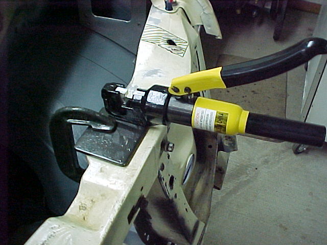
I clamped the Hydraulic Crimper right to the rad support and got busy. This little mod is turning out to be pretty handy...
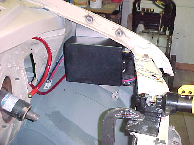
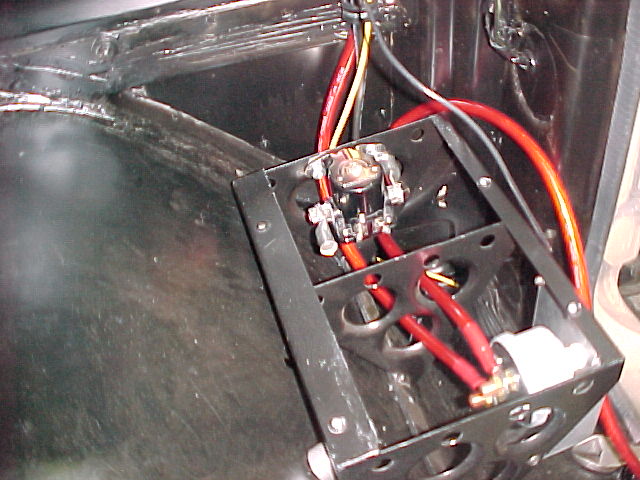
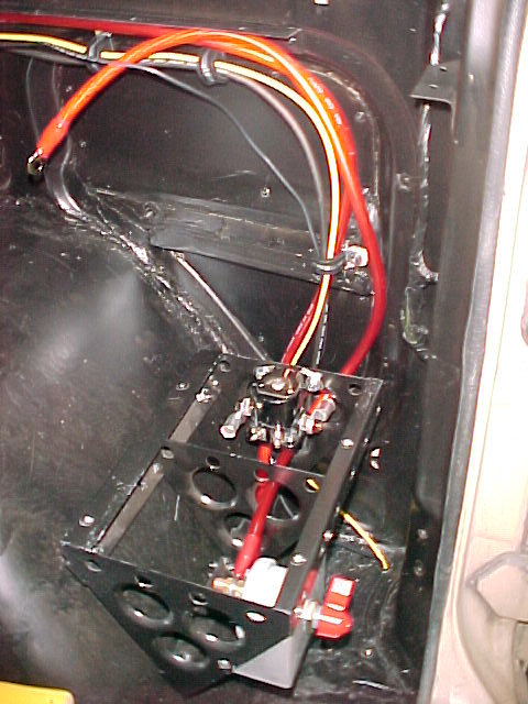
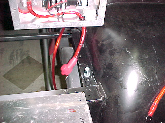
I hung the relay box and routed the wires in some semblance of how they will be when installed.
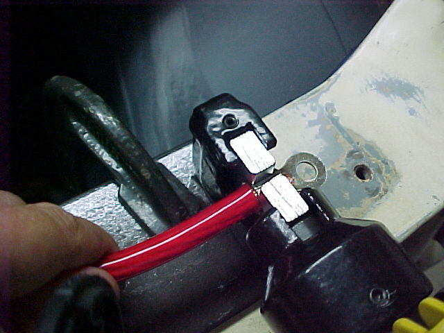
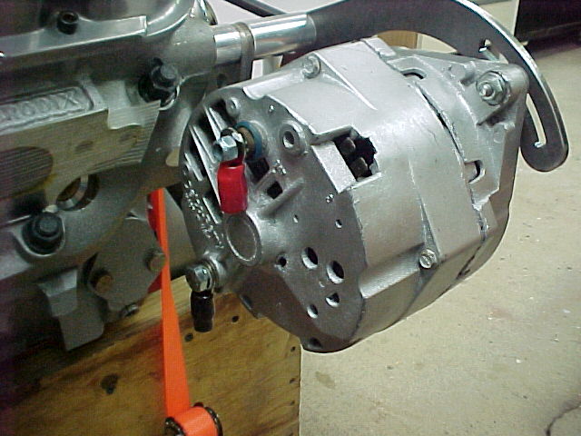
I got the power lead for the relay box, the charge/power lead for the battery (from the back), the power lead for the fuse box and the power lead from the alternator all crimped tonight. Once I got going it took about a half hour to do all of the crimps.
")
Having the crimper right there, where I was working, was nice!
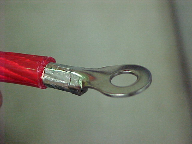
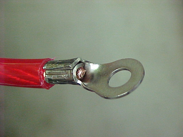
These are some very tight crimps...
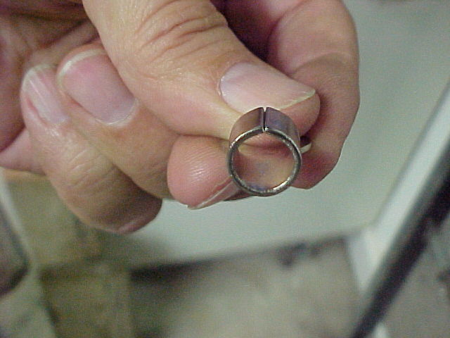
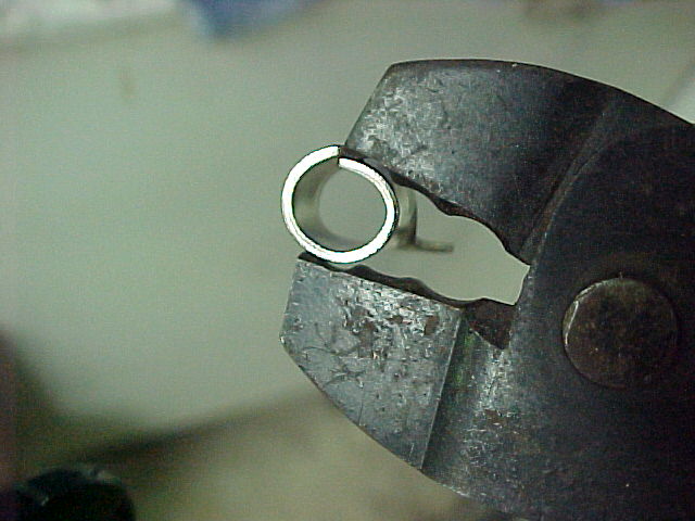
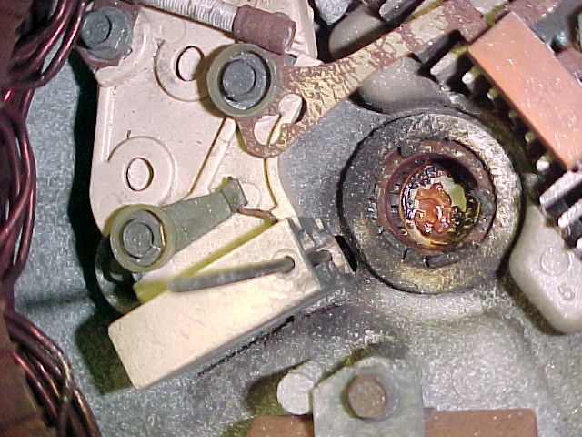
I did learn a bit tonight. The terminals I am using are rolled, with the seam at the top, as you can see here.
After I did the first one (which I got lucky on) I decided to pinch the terminals closed a bit so one edge is "tucked" under the other. When doing this the edge getting tucked will actually "snap" under the top edge.
This guides the crimp into a very tight roll. I think it compresses the wire about half it's diameter, just looking at it...
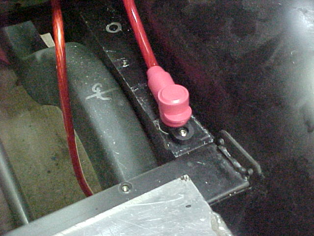
This ready for some heat shrink.
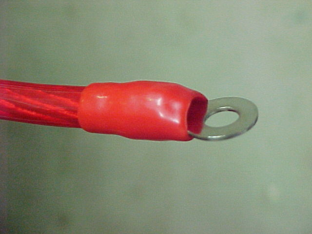
I need to get some larger diameter red shrink (this is just the plastic boot that came with the terminal)... I could use black I guess but I am trying to make this stuff look like I thought about it before I did it.
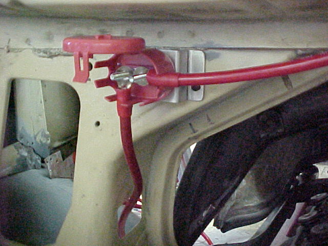
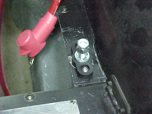
Here is the power block I mounted last week with the cables loosely routed.
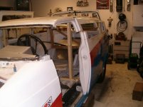
Here is a pic of the relay center with the cover in place... This will get painted body color so it will all but disappear after install.
That's what I did.
Mark