You were right about the radius - I laid the part down on a piece of paper and traced the inside and outside of the bend. I took a compass and set it to the midpoint between the two - the bend radius is right around 3.5", vs. the 2.5" I originally thought.You didn't measure radius accurately from your master part. The die does have to be slightly smaller (due to spring back) but in your case, you are a LONG way off. You need to measure your newly bent piece very carefully to get a value for spring back then select a new die radius that allows for it. How have you been measuring up to this point?

You are using an out of date browser. It may not display this or other websites correctly.
You should upgrade or use an alternative browser.
You should upgrade or use an alternative browser.
Bending Tubing - Need Advice
- Thread starter paulsomlo
- Start date
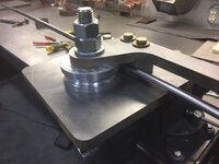
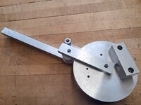
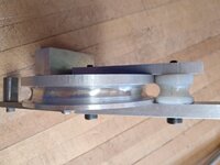
I haven't made much progress on this, been off on other things. I did buy the bender shown below off ebay for cheap, to see how it differs from what I've thrown together. Maybe one of you bending experts can tell me - what's the difference between what I bought off ebay, what I threw together, and a rotary draw bender? The one I threw together, the bending form is stationary and I use a roller to bend the tube around it. The one I bought, the bending form moves and the shoe is stationary. It does seem similar to the rotary draw benders I see on youtube, although the more sophisticated ones use both clamping shoes and a stationary shoe, which I suppose is at the tangent point. I also see some that use a follow shoe as well.
I'd like to understand the physics behind these things in terms of what type will give me the best bend quality.
I'd like to understand the physics behind these things in terms of what type will give me the best bend quality.
Attachments

Graham08
Well-known member
I would consider your ebay purchase a "rotary draw" type bender. The round die rotates and draws the tube through the follow block. It's just all one piece since it's a dedicated bender for a single size of tube. I think it was made by Imperial...so you might be able to find some documentation of it on the web.
The one you made, Hossfeld, JD2 Model 4, etc. are rotary compression benders. The round form is stationary and the follow die compresses tube into it.
I would recommend checking out the 44 Bikes frame shop thread in the Garage Gallery forum. Kristopher makes his own tooling for a Diacro bender and has some discussion of the things you're asking about. It's too bad the old offroadfabnet site is gone...it was run by Cris at Bend Tech and benders were discussed in a lot of detail. I think the Bend Tech documentation on their site is another good reference for the finer points of bending.
The one you made, Hossfeld, JD2 Model 4, etc. are rotary compression benders. The round form is stationary and the follow die compresses tube into it.
I would recommend checking out the 44 Bikes frame shop thread in the Garage Gallery forum. Kristopher makes his own tooling for a Diacro bender and has some discussion of the things you're asking about. It's too bad the old offroadfabnet site is gone...it was run by Cris at Bend Tech and benders were discussed in a lot of detail. I think the Bend Tech documentation on their site is another good reference for the finer points of bending.
4 FN 27
ALLIANCE MEMBER
I am a little late to the party. I made this "Mini Bender" for doing .065 wall Stainless. Perfect Bend every time. Seeing the pieces you made so far you can make this.


Last edited:
Graham08
Well-known member
Nice work, Pat! What size tube is that? Looks to be maybe 1/2"...
4 FN 27
ALLIANCE MEMBER
Nice work, Pat! What size tube is that? Looks to be maybe 1/2"...
3/8 diameter.
Will do, thank you!I would recommend checking out the 44 Bikes frame shop thread in the Garage Gallery forum. Kristopher makes his own tooling for a Diacro bender and has some discussion of the things you're asking about. It's too bad the old offroadfabnet site is gone...it was run by Cris at Bend Tech and benders were discussed in a lot of detail. I think the Bend Tech documentation on their site is another good reference for the finer points of bending.
Very nice - it appears that the moving shoe doesn't conform to the tubing exactly, there's a little space; is that not an issue? And your bending form - does it match the tube radius exactly? I was watching a JD-2 video, and they claim that their bending form radius differs from that of the tube and that it's a feature. I've also come across this website that talks about "multiple radius" for the tube groove: https://www.toolsforbending.com/empty-bending-applications/I am a little late to the party. I made this "Mini Bender" for doing .065 wall Stainless. Perfect Bend every time. Seeing the pieces you made so far you can make this.
With the bender I threw together, the start and stop points of the bend are noticeable on the inside of the bend, where on the part I'm trying to copy, that distortion is not noticeable. I'm not sure if it's due to the fact that the original has a 3.5" bend radius, where mine is 2.5".
Last edited:
isb cornbinder
Well-known member
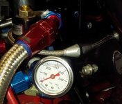
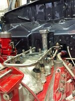
I have that tube bender along with the complete set of Ridgid LAB tube benders. Your tube bender is fantastic. I formed the common rail tube for the injectors on my '40 Ford Flathead V8.The tubing is 6063; I can see this is a non-exact science - I'll have to finish the bending apparatus and hopefully, display the results here. Enjoyed your photos!
My best advice is to carefully bend some tube like what you intend to use and make adjustments to suit. It is important to know where the inside radius will finish.
I was allowed a a difference of .03125"
The common rail tubing on my Flathead is a one meter piece. (.44") stainless. Even though this is expensive I bought two, one meter lengths, just incase. I can tig-weld, maybe, just OK. So, I paid a professional a $100/hour to TIG the injector adapter caps to the tube.
The pressure will be limited to 45psi. This is controlled by a residual check-valve that is boost referenced.
Attachments
-
 MARSHALL GAUGE 2.jpg45.9 KB · Views: 23
 -
 FUEL GAUGE INSTALLED.jpg63.2 KB · Views: 16
 -
 FUEL GAUGE TOP VIEW.jpg89.9 KB · Views: 13
 -
 BOOST REFERENCED RESIDUAL FUEL PRESSURE VALVE leak at this fitting.jpg76.7 KB · Views: 13
 -
 INJECTORS.jpg148 KB · Views: 15
 -
 ENGINE NAKED.jpg49.7 KB · Views: 16
 -
 ENGINE LE 1.jpg55.1 KB · Views: 18
 -
 RIDGID 400 Series Instr. Bender_72dpi.jpg23.8 KB · Views: 16
 -
 TBS200 SnapOn tube bender.jpg12.6 KB · Views: 16
 -
 TUBE BENDERS RIDGID.jpg70.9 KB · Views: 27
4 FN 27
ALLIANCE MEMBER
Very nice - it appears that the moving shoe doesn't conform to the tubing exactly, there's a little space; is that not an issue? And your bending form - does it match the tube radius exactly? I was watching a JD-2 video, and they claim that their bending form radius differs from that of the tube and that it's a feature. I've also come across this website that talks about "multiple radius" for the tube groove: https://www.toolsforbending.com/empty-bending-applications/
With the bender I threw together, the start and stop points of the bend are noticeable on the inside of the bend, where on the part I'm trying to copy, that distortion is not noticeable. I'm not sure if it's due to the fact that the original has a 3.5" bend radius, where mine is 2.5".
In theory there is no space. The Radii on the Die, Follower and Block are the Diameter of the Tube. What you are seeing is a combination of tolerance buildup and no pressure on the system.
After the Tube is bent, without a Mandrel the Tube becomes obround to a certain extent. Nothing to worry about unless it matters.
The Inside Radius, Centerline Radius and Outside Radius will never mathematically add up (without a Mandrel). The inside of the tube is compressing, the outside is stretching and the centerline is a byproduct of both divided by 2 in any given cross section throughout the bend. It will not be a true centerline radius either. It will be a non-linear radius. Doing it like this should eliminate the Die Marks you are seeing unless the tube is really thin and the Radius is small.
The tighter the Radius the thicker the wall needs to be to keep it from collapsing. Kind of the nature of the beast. Imagine trying to take a straw and putting a 2 inch radius bend in it. It is going to collapse. Take the same straw and put a 200 inch radius in it and it will probably work. Like a Garden hose, tubing can only bend so far before it kinks.
Looking at the link, yes that will help but the question is how much R&D are you willing to put into it for a given diameter and radius?
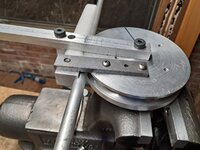
Here's an update - I incorporated some of the suggestions that were made here; I added support to both sides of the roller and used shoulder bolts, adding a block to the backside to keep it from rotating in the vise.
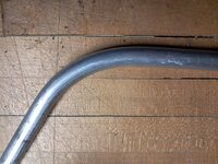
The bender works fairly well, for what it is - the only misgiving I have, is I can still see that slight distortion where the bend begins and ends; can anyone enlighten me as to what causes that? Would that be eliminated by using a follow block, rather than a roller? In the photo here, the bottom most of the three samples is the original that I'm trying to replicate, with my two attempts above. The original is roughly 3.5" radius vs my bender of 2.5" radius. I'm told that the original was bent using a three roll bender.
The bender works fairly well, for what it is - the only misgiving I have, is I can still see that slight distortion where the bend begins and ends; can anyone enlighten me as to what causes that? Would that be eliminated by using a follow block, rather than a roller? In the photo here, the bottom most of the three samples is the original that I'm trying to replicate, with my two attempts above. The original is roughly 3.5" radius vs my bender of 2.5" radius. I'm told that the original was bent using a three roll bender.
Attachments


Firebrick43
Well-known member
The distortion comes from upsetting the metal on the inside and stretching the metal on the outside.
It will always be present if you measure to some degree. Really good benders have dies that are actually not round where the tube set, but oval to counteract the tubings tendency to squat (radial cross section) in the bend. The bump you see is that difference in tubing cross section height.
Even better benders (more than likely the production pieces used one) are mandrel benders.
They use a mandrel (bullet shaped) that is attached to a chain or cable and pulled through the pipe(or you could say the pipe is pushed/pulled around the mandrel?). That mandrel is in essence always where the bend is taking place on the inside of the tube and keeps the collapsing of the tube in the bend to a minimum. It’s still does slightly(you can measure it) but it’s pretty hard to tell visually.
It will always be present if you measure to some degree. Really good benders have dies that are actually not round where the tube set, but oval to counteract the tubings tendency to squat (radial cross section) in the bend. The bump you see is that difference in tubing cross section height.
Even better benders (more than likely the production pieces used one) are mandrel benders.
They use a mandrel (bullet shaped) that is attached to a chain or cable and pulled through the pipe(or you could say the pipe is pushed/pulled around the mandrel?). That mandrel is in essence always where the bend is taking place on the inside of the tube and keeps the collapsing of the tube in the bend to a minimum. It’s still does slightly(you can measure it) but it’s pretty hard to tell visually.
By "oval", do you mean where the sides of the tubing contact the die, it's narrower?The distortion comes from upsetting the metal on the inside and stretching the metal on the outside.
It will always be present if you measure to some degree. Really good benders have dies that are actually not round where the tube set, but oval to counteract the tubings tendency to squat (radial cross section) in the bend. The bump you see is that difference in tubing cross section height.
Even better benders (more than likely the production pieces used one) are mandrel benders.
They use a mandrel (bullet shaped) that is attached to a chain or cable and pulled through the pipe(or you could say the pipe is pushed/pulled around the mandrel?). That mandrel is in essence always where the bend is taking place on the inside of the tube and keeps the collapsing of the tube in the bend to a minimum. It’s still does slightly(you can measure it) but it’s pretty hard to tell visually.
I've spoken to someone who was involved in the manufacture of the original tubes - I don't believe they used a mandrel.
@4 FN 27 Do the bends produced with your bender have that telltale "bump" at the beginning and end of the bend?I am a little late to the party. I made this "Mini Bender" for doing .065 wall Stainless. Perfect Bend every time. Seeing the pieces you made so far you can make this.
I would suggest the OP build a closer to correct inner die and not worry about the cross sectional distortion (nothing has to fit there). BUT: there should only be a "dent" at the end of the outer roller travel. The "start hook" shouldn't be making a dent. The best reason to use a flat/straight plastic moving die is so it can park right up tight to the start clamp. Roller dies run into things, so clamping has to take place a bit further back the fixed starting side. If OP wants to stay roller I would be comfy going with his original 2.5 die and move the fixed starting clamp back down the pipe. I did that with my rolling outer die bender by clamping to the start holder rather than just hooking in placeThe distortion comes from upsetting the metal on the inside and stretching the metal on the outside.
Last edited:
Firebrick43
Well-known member
Not necessarily narrower in the sides the radius in the die isn’t constant.By "oval", do you mean where the sides of the tubing contact the die, it's narrower?
If you cross sectioned a bend and look at it from pependicular from the plane you cut the tube will be oval, wider from side to side from a die that is circular in shape.
(I will post a pic when I get home tonight)
By making the die itself distorted counter to the shape it will tend to cancel out and be rounder after spring back of the metal from being formed.
Unfortunately it’s something that is very dependent on the type of metal and the of and wall thickness. They are made on CNC lathes that can generate the complex profile.
You can place radius gauges in better made dies and see the differences. It would be hard to measure exactly except by CMM machines. It’s not easily to replicate at home
Last edited:
Firebrick43
Well-known member
I don’t see the start hook making a dent? I see the cross section on the inside of the bend radius(where the bend radius starts and stops) is the “dent” I think he is talking about. It’s not really a dent, it’s a cross sectional change in profile.I would suggest the OP build a closer to correct inner die and not worry about the cross sectional distortion (nothing has to fit there). BUT: there should only be a "dent" at the end of the outer roller travel. The "start hook" shouldn't be making a dent. The best reason to use a flat/straight plastic moving die is so it can park right up tight to the start clamp. Roller dies run into things, so clamping has to take place a bit further back the fixed starting side. If OP wants to stay roller I would be comfy going with his original 2.5 die and move the fixed starting clamp back down the pipe. I did that with my rolling outer die bender by clamping to the start holder rather than just hooking in place
Correct - at that point, the tube diameter changes by -0.013" in the dimension that corresponds to the depth of the fixed die, and by +0.004" in the dimension across the width of the fixed die.I don’t see the start hook making a dent? I see the cross section on the inside of the bend radius(where the bend radius starts and stops) is the “dent” I think he is talking about. It’s not really a dent, it’s a cross sectional change in profile.
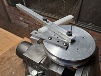
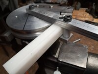
Here's what I believe is the final revision - the roller was leaving a "dent" on the outside of the bend where it stopped, so I replaced it with a follow block of delrin that's held captive by a shoulder bolt with a delrin sleeve around the shoulder for bearing. I made a new keeper that conforms to the tubing - the arm on which it's attached is fixed, but the keeper can rotate slightly. The bend quality is much improved, probably about as good as it can get with this style bender and no mandrel. Thank you all for your suggestions and insight.