To avoid these ads, REGISTER NOW!

Black and Decker bench grinder wiring help

Sawmill7

Well-known member
Joined
Sep 3, 2019
Messages
253
Location
Iron River Mi
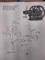
Doing a resto on vintage black and decker 1 h.p bench grinder. It does work but after disassembling it wiring does not look correct. Previous owner had been replaced some wiring and just does not look correct.
Capacitor has only 2 spades but has 3 wires, 2 on a spade and 1 on the other spade.
The drawing in the picture is how it's wired now
But want to replace wires correctly.
Also no markings on capacitor so need to know correct size to replace it. Thanks for any help with my project. Bill
 

Attachments

  • IMG_20251213_112446213_HDR.jpg
    IMG_20251213_112446213_HDR.jpg
    516.2 KB · Views: 27
To avoid these ads, REGISTER NOW!

PCustoms

Well-known member
Joined
Jul 23, 2011
Messages
23,393
Location
VT
The "hot" wire should be switched, not the neutral

Pictures of the actual wiring may be helpful
 
OP
S

Sawmill7

Well-known member
Joined
Sep 3, 2019
Messages
253
Location
Iron River Mi
Here is how it was wired. I know the black should go to and from switch. As I stated it did work but old wiring is mess.hope this pic helps
 

Attachments

  • IMG_20251213_115420821_HDR.jpg
    IMG_20251213_115420821_HDR.jpg
    1 MB · Views: 24

justsam

Well-known member
Joined
Aug 20, 2010
Messages
1,268
Location
Penngrove, California
Doing a resto on vintage black and decker 1 h.p bench grinder. It does work but after disassembling it wiring does not look correct. Previous owner had been replaced some wiring and just does not look correct.
Capacitor has only 2 spades but has 3 wires, 2 on a spade and 1 on the other spade.
The drawing in the picture is how it's wired now
But want to replace wires correctly.
Also no markings on capacitor so need to know correct size to replace it. Thanks for any help with my project. Bill
I see no issue other than would look more professional if black to black and white to white. as has been mentioned, and switch black lead. The single lead, small white from motor, on the capacitor is one side of the start winding. The two leads on the capacitor should be power and one side of run winding from motor.
 
To avoid these ads, REGISTER NOW!
OP
S

Sawmill7

Well-known member
Joined
Sep 3, 2019
Messages
253
Location
Iron River Mi
So I do need 2 wires to one side of capicator?
Do you have any thoughts on specs for a new capicator? Want to replace as long as I have it apart. Thanks
 
Last edited:

justsam

Well-known member
Joined
Aug 20, 2010
Messages
1,268
Location
Penngrove, California
If the grinder is currently starting OK, I am not sure why you want to replace the capacitor. Can you see any markings on it? Since a grinder application typically does not start under load, I would guess the value to be around 100 uFd. Not too critical as if it does it's job by starting the motor it is out of the circuit once running. The capacitor lug with two wires is just a convenient tie point. If electrically one side of the capacitor, one leg of power and one motor lead are connected together it does not matter how you got there. The single wire on the capacitor is one side of the motor start winding. If you do change the capacitor it must be for motor start application as it requires a non polarized capacitor and a typical electrolytic will not work here.
 
To avoid these ads, REGISTER NOW!
Top Bottom