To avoid these ads, REGISTER NOW!

Between 265 & 485 SQ/FT Building a 16x22 Gambrel Workshop

Workspaces sized between 265 and 485 squarefeet.

old_smokey

Well-known member
Joined
May 16, 2018
Messages
410
Location
Manitoba
Hi all,

After around seven years working out of my little 1940's 12x20 shop, the time has come to tear it down and start fresh.

My wife and I have decided to stay put in our home for the long term, so it makes sense to invest in a new shop. The trouble is, our lot is small at 100' x 30'. After playing with a wide range of ideas, talking to the city permit office and exploring options for variances, I've settled on building 'up'. The plan is a 16x22' slab with radiant heat, a gambrel/barn roof, and DIY carriage doors.

I'll be contracting out the concrete work, but everything else will be done by yours truly. I have only limited experience in framing, finishing, siding, and electrical work, so this project will be a challenge and a big learning experience for me. Thankfully, my Dad recently retired and has graciously offered to help me with a lot of this work. That should make the whole process a lot more fun, too.

I hope you'll join me as I build my little dream shop. I'm busy moving out of my current uber-cramped shop as demolition starts after easter weekend!

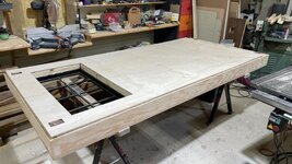
Before getting underway, here are a few pics to show just how absurdly overcrowded my current shop has become!

IMG_2929.jpg
D03F271FEFA1_1689991460.JPG
 
Last edited:
To avoid these ads, REGISTER NOW!
OP
O

old_smokey

Well-known member
Joined
May 16, 2018
Messages
410
Location
Manitoba
While this thread is new, I've been working on planning the new shop for the past 2-3 years as I squirrelled away the cash. Over the past year or two, I tackled the planning and paperwork stuff: property survey, review of the bylaws in our area, meetings with planning dept to go over my preliminary ideas and identify any possible problems.

I learned that because I was technically building a two-story structure, I was required to have stamped drawings for my foundation and framing. I found a local structural engineer who would review and stamp my drawings for $1,000, but I had to give him proper drawings.

In an effort to save money, I learned Sketch-Up over the winter, and was able to deliver adequate details for my engineer to approve. This was a huge cost savings, and a fun way to visualize how the building would come together.

Screen Shot 2023-11-09 at 10.11.18 AM.png


Here is an example of what I was initially thinking to build - just a rough concept, obviously. I wanted the upper roof pitch to be as flat as possible to maximize storage. The roof would utilize a ridge beam and gussets on the rafters. This design fully conformed to the published city guidelines at the time.

Sadly, my drawings were promptly denied by the city. It turns out they had just revised their gambrel roof height bylaws. My shop was 1' too tall. The new regulations measured roof height at the half-way point of the upper rafter pitch.

To keep it short, there was much back and forth, arguing, revisions, and an additional variance required before I was able to get my project approved and permit in hand. This happened just last month actually.

elevations south wall.png

This shows a more accurate view of the approved roof profile. It isnt' as proportional as what I had initially designed, but it balances maximizing headroom with bylaw compliance

Screenshot 2025-04-10 at 12.26.00 PM.png
And here is what the rafter construction will look like. It's a bit of an awkward shape to cut, but it will allow me to push the ceiling height up into the roof, without getting an even more unusual gambrel shape.

Screenshot 2025-04-10 at 12.27.23 PM.png
And here is my last rough rendering, showing what the shop will look like with a metal roof on.

With permits in hand, it is time to start thinking about materials, building doors, and demolition!
 
Last edited:
OP
O

old_smokey

Well-known member
Joined
May 16, 2018
Messages
410
Location
Manitoba
My shop is a place for working and hobbies, not for parking. So I've always liked carriage doors compared to traditional overhead doors. They are also a lot more secure against break-ins, something that is sadly very common where I live.

Actually, three years ago, 50% of the garages on my block were burglarized. All of them gained access via the overhead doors, by prying them off the tracks. I live in a lovely neighbourhood, but it is surrounded by a few that are less than lovely. So security is a major consideration in this project.

I decided to tackle constructing my own carriage super-doors. The would have to be strong and keep people out. They would have to be tall and wide, so I could carry material in. They would have to be super-insulated, as it gets very cold here. And of course they would have to be beautiful.

After scouring Garage Journal for examples, I decided to build a hybrid construction - steel frame, rigid foam interior, and wood skin.

D03F271FEFA1_1734404831.JPG

Building these in my little 12x20 shop was hilarious and at times downright dangerous lol. I built them out of .100 wall 2" square tubing. I used string lines to check for flatness, and did my best to minimize distortion.

Screenshot 2025-04-10 at 1.02.25 PM.png

Half way through, I got a deal on some Rock Glass, an impact-proof 12mm thick polycarbonate material used for theft-proof windows. I decided to add windows in my doors, so long as I could be confident nobody could break through them.


IMG_7373.jpg

IMG_7404.jpg

I welded a frame out of angle, then some security bars from solid 1/2" square bar. I added in a piece of 1/8" flat bar at the bottom, sloped outward as a window sill. A sheet of cold rolled sheet metal was added to the lower frame, making these pretty much impossible to get through without some serious effort. Thanks to my Dad for coming over and helping me flip these over while I welded them together!

IMG_7422.jpg

IMG_7403.jpg
IMG_7410.jpg


IMG_7452.jpg

Then it was time to weld the hinges in place and give everything a thick coat of red oxide primer.

IMG_7520.jpg

I was pretty happy with my welding until my overhead heater would kick in and blow the shielding gas away!

If you're curious, these weighed around 150lbs each at this point, if my memory is correct. Everything was TIG welded due to my confined space and wood floor. It took two tanks of argon and about 10lbs of filler wire. Now it's time to turn my focus to making them look pretty!
 

Attachments

  • IMG_7440.jpeg
    IMG_7440.jpeg
    556.6 KB · Views: 32
Last edited:
OP
O

old_smokey

Well-known member
Joined
May 16, 2018
Messages
410
Location
Manitoba
I wanted these doors to look as unassuming and traditional as possible. I got a really good price on some Douglas Fir, so I decided to try making a frame with it. The shop will be sided in LP Smartside, so I picked up a matching panel to use as well.

My thinking was that I'd make the front face fairly thick, so it has some depth to the design. The sides and back would be thin plywood. Maybe 3/8 or 1/2 on the side, and thinner on the back. Rigid foam would fill in all the rest.

My Dad has been a lifelong woodworker. He's a huge wealth of knowledge for me and always pushes me to do things as best I can. He recommended I assemble the doors with mortise and tennon joints, even if their strength wasn't needed on account of the steel frame. Sounds fun!

IMG_7598.jpg

I did all the woodwork in my Dads shop, just a few minutes down the road from me. He's got a way bigger space and all the tools you would need. He kindly let me take over for a couple of weekends while I built the frames and assembled the doors.

IMG_7607.jpg

The diagonal bracing was the toughest part. This will be glued to the door, rather than a mortise and tenon. In hindsight, that might have been a mistake. The material warped and cupped significantly after milling, and I still need to re-do this section.

IMG_7478.jpg

Here I am standing next to a rough assembly for scale. Proper door size!

IMG_7612.jpg

And here is the LP panel glued and nailed into the back of the frame. The diagonal brace isn't glued up yet as I need to fix a few things with it first.

IMG_7632.jpg

Next up, I used some mahogany I found buried in my backyard (that is a whole other story...) to make some drip caps. This will be above and below the window, and at the bottom of the LP panel. I did this partially do keep water out of the doors, and partially because I screwed up my measurements and needed to hide some mistakes haha. It happens.

Next up, insulation
 

Attachments

  • IMG_7609.jpg
    IMG_7609.jpg
    715.9 KB · Views: 34
  • IMG_7602.jpg
    IMG_7602.jpg
    730.2 KB · Views: 33
OP
O

old_smokey

Well-known member
Joined
May 16, 2018
Messages
410
Location
Manitoba
I brought the steel frames over to my Dad's shop and started cutting foam to fit. This was a much more finicky process than I expected. In hindsight, I would have made these doors completely differently. I thought using plywood over a steel and wood frame would make it easy to shim and tweak everything square/plumb, but it was just frustrating!

IMG_7678.jpg

IMG_7744.jpg

For one door, I built a tapered jamb so the doors don't bind when opening. As I only did this to one door, it means one has to open or close before the other. Since I don't park in the shop, I will 99% just be using one door anyway.
You can also see where the Douglas Fir chipped when handling the door frames. That was another lesson. Douglas Fir has great weather properties but checks and cracks easily. A hardwood would have been a better option, but much heavier.


IMG_7675.jpg
IMG_7710.jpg

You can see some small square steel 'stand offs' in each corner. These are where I will bolt on the door locks. The long term plan is to look at building some remote locks with linear actuators and a wireless FOB.

IMG_7715.jpg

I ended up using 3/8" birch ply for the back skin. I had 1/4" but it was so thin that I couldn't get it to sit flat enough.

IMG_7725.jpg

And here is the skin nearing completion. I cut some thin square pieces to fill in the corners. It turned out quite nicely almost everywhere, with a few small exceptions, as pictured. You can see in the upper corner, my plywood jamp doesn't sit quite flush. I'll be fixing that before installing.

To finish the doors, I need to install the glass, make window trim, and finish the doors with Spar Urethan and paint prior to installation.
 

Attachments

  • IMG_7713.jpg
    IMG_7713.jpg
    632.3 KB · Views: 27
OP
O

old_smokey

Well-known member
Joined
May 16, 2018
Messages
410
Location
Manitoba
Something I've been thinking about a lot is the weight of these doors and how to adjust them once installed. They are going to be just a tick over 300lbs each once the glass is installed. I have plans for building a very HD door frame with some rough sawn oak I have stashed away. But the chances of getting them installed perfectly with no provision for fine tuning sounds like a recipe for disaster to me.

So, I need to design some adjustable hinges that are up to the task of holding 300lb doors.

One of the issues I'm struggling with is how to do this given my wall construction. I'm building with 2x6 framing, then 7/16 OSB, 2" rigid foam, a 3/4" rainscreen gap, and finally the siding. That means my door frame will be much thicker than the wall framing. I calculated that I need to use 2x10's in order to push the door far enough out of the shop to open fully. Here is a quick mock-up to illustrate the issue:

IMG_7804.jpg

So I decided to extend my hinges so they run all the way to the interior edge of my 2x6 studs. That will let me thru-bolt the hinges to the framing. But what about adjustability? I could just shim the hinges as needed, but that isn't my style.

Screenshot 2025-03-01 at 1.11.22 PM.JPEG
Screenshot 2025-03-01 at 1.12.41 PM.JPEG

I devised the following hinge design. The hinge itself has 1/2" bolts or threaded rod to clamp it to the framing. But between the hinge and the 2x10 wood frame sits a second piece of steel. The hinges will have a series of grub screws which establish the gap between the two steel plates. By loosening off my mounting bolts, then adjusting the grub screws, I can dial the hinge in and out as needed.
I made the hinges with 3/8" plate. The inner plate is 1/4".

The hinge bolts thread into drilled and tapped DOM tubing, using 1/2" fine thread. My plan was to weld DOM tubing to the stationery plate so that it would telescope. My thinking was this would provide additional support for holding the weight of the doors, cantilevered to the outdoors. In the end, It was much too precise a fit. After welding, it would bind, so I abandoned that part of the plan.

IMG_7867.jpg

IMG_7848.jpg
IMG_7863.jpg

In that last photo, you can see a fully built hinge in the back, and one waiting for welding in the foreground. I drilled a pilot hole in the hinge first, then welded front and back, then drilled and tapped to finish size.

IMG_7861.jpg

The design on the right is what I landed on. It still slides relatively easily here. All that was left is drilling and tapping the holes for adjustment grub screws, and paint.\

Just before wrapping up, I realized another mistake I made on the doors. I welded the hinge to my doors exactly where my concrete curb meets the wall bottom plate. That means I have no way to bolt the hinge through the framing. While annoying, it wasn't tough to fix. I had some leftover 3/8 plate, so I just make an enormous lower hinge plate. I'll use my router to carve out a pocket for this plate, and that leaves me with a ton of real estate to bolt the hinge through my framing slightly higher up.

IMG_7886.jpg

This weld nearly killed my CK17 torch haha. 215 amps, wide open.

And that brings us pretty much up to the present day. I spent the last week moving my shop into storage in anticipation of demolition. I've managed to sell, donate, repurpose or save the vast majority of my shop's materials, as I'm on the tightest of budgets here.

IMG_8023.JPG

That's it for updates for the time being. Demolition is in less than two weeks. Then it's time to start thinking about the slab and radiant layout.
 
OP
O

old_smokey

Well-known member
Joined
May 16, 2018
Messages
410
Location
Manitoba
Just a quick update today - my old shop is officially gone. I spent 7 years working in that little box and I admit I was a little conflicted watching it get torn apart.

On the weekend I sold off the overhead door, steel man door, and stripped nearly all the wiring out of the walls. By the time this morning rolled around, there was pretty much nothing left to demolish except the wood structure itself.

Took three guys and a skid steer about six hours. Really glad I didn't do the demo myself. For the price they charged, I don't think I could have done it for more than a couple hundred bucks less.


IMG_8146.jpg


Now it's a mad dash to get everything ready for concrete this weekend!
 

RyanE

Well-known member
Joined
Feb 4, 2013
Messages
201
Location
Golden, BC
Awesome!

I thought your former shop looked familiar in the first few photos. I can't recall if you had posted a build thread here or on advrider.com. But I recall you had an XR650 I think? I do as well.

Such a great (albeit small) space you had created, especially the salvaged school gym floor.

In any case, this new shop should be a great upgrade. I really enjoy these small builds that require thoughtful use of space and organization since I too am limited to a small space as well.

Looking forward to updates.
 
OP
O

old_smokey

Well-known member
Joined
May 16, 2018
Messages
410
Location
Manitoba
Awesome!

I thought your former shop looked familiar in the first few photos. I can't recall if you had posted a build thread here or on advrider.com. But I recall you had an XR650 I think? I do as well.

Such a great (albeit small) space you had created, especially the salvaged school gym floor.

In any case, this new shop should be a great upgrade. I really enjoy these small builds that require thoughtful use of space and organization since I too am limited to a small space as well.

Looking forward to updates.
Yeah that's probably me! I had a XR650L for a long time. I sold it about two years ago and bought a XR650R, which I absolutely am loving. Might be a forever bike.

I gave the salvaged gym floor to a friend of mine for his shop. It's on to it's third-life now, which I think is so cool. I loved that floor. It was so comfortable to stand on for hours.
 

mschoo92

Well-known member
Joined
Oct 2, 2023
Messages
74
Location
Sussex County, NJ
Very nice. Looking forward to see the new building start to be built, based on your SketchUp design that should be a nice workshop garage!
 

Ford52PU

Well-known member
Joined
Aug 7, 2007
Messages
798
Location
Coatesville PA
wow if those doors are any indication of how your building the rest of the shop, cant wait to watch this go up. Nice job!
subbed
 
OP
O

old_smokey

Well-known member
Joined
May 16, 2018
Messages
410
Location
Manitoba
Hi all, back with another update.

A lot has happened since I last posted. Concrete work is done, and the building has started to go up.

I hired out the concrete work but was hands-on for getting the insulation and radiant heat details correct. My city permit office required an engineered foundation, so I was also on-site to ensure everything was done according to the drawings. It was good I was, as there were a few relatively minor things they missed that were corrected before the pour.

WhatsApp Image 2025-05-01 at 12.47.35.jpeg

The slab has 16" thickened edge footers, a 6" centre, 1/2" rebar on chairs, 35MPA mix, power troweled, all poured over 25psi EPS foam. After the slab was done, they came back and epoxy doweled the edges and poured a 6" curb. Then I wrapped the perimeter in 3" XPS my Dad had sitting in his shop for years. Next, I tapcon'd some PWF plywood over the foam as a protection board. I'll cover this later with something. Maybe parge it, coil stock, paint it black, whatever.

IMG_8237.jpg

The surface finish of the slab is really nice. Super smooth and hard. I asked for it to be level and flat. It's pretty darn close, but a couple of high spots bug me. I'm unsure how flat a power trowel is expected to get things, but I was expecting a little better. The vast majority of the slab is great, but there are two high spots/humps, which are probably 3/8" tall when I lay a long level over them. It's fixable if I wanted to grind it down, but then I have a new problem of an inconsistent surface finish. I don't want to paint or epoxy coat the surface. Out of curiosity, I got quotes to grind the spots down and polish the whole slab to a uniform finish. It's almost $4,000, so I will just have to live with it. Thankfully, they are both close to a wall, so they'll be buried under a workbench anyway.

Outside of those two spots, the rest of the concrete work went well. My radiant system held pressure throughout the pour and saw cutting. The apron/driveway has a nice broom finish, and they managed to tie it into my neighbour's driveway seamlessly.

After letting the concrete sit for 1.5-2 weeks, I got my first order of lumber. With such a small yard, I have to order everything in small batches. Pretty annoying, but it is what it is.

IMG_8368.jpg

My Dad came by to help me stand up some walls. Between the two of us, we made quick progress.

IMG_6772.JPEG

IMG_8370.jpg

PHOTO-2025-05-19-21-04-50.jpg

Yesterday, we aimed to get the ceiling joists up. If there is one consistent aspect of this project so far, it's that dimensions are never quite as expected. My 2x12x16 joists range from 10-15/16 to 11-1/4.


I'm sure pro framers will laugh at this. But since I'm just an amateur here, and I don't want to chase or compound errors all the way up through framing the rafters, I'm trying to set myself up for success by getting every 'layer' perfect. I spent a bunch of time grinding my curb's high spots, after finding one corner was 1/2" taller than the rest of it. Then I cut all my 8' studs to exactly 8 feet, after seeing similar variances. Then I shimmed between my two top plates, so I'd end up with a perfectly flat second top plate. Checking with a laser, I was within 1/16 all the way around.

For fixing the joists, my Dad and I teamed up again. We made up a long straight edge guide and ran a router with a bearing bit along the edge. Then, using that new straight side as a reference, repositioned the template to do the opposite edge, ending up with a consistent, parallel set of edges. I know this wood will swell, twist, warp and cup in time, but I want to at least start with something I know is dimensionally consistent.

IMG_8391.jpg

All this work takes a huge amount of time. By the end of the day, no joists were set in place. But we did get the rim joist and double 2x12 header installed. For the big door opening, I PL glued and nailed the two 2x12s together, along with a 2x6x16 along the underside. This week I'll add another 2x6x16 to the top side, creating a huge I-joist.

The last task of the day was fitting the man door. Garage break-ins are common in my area, so I bought a new commercial steel door off Marketplace last year. It was a 3x7 door with a solid foam core. Really heavy and strong door. I installed the frame and hung the door. Everything lined up perfectly until I realised the deadbolt was a few inches offset from the striker plate. Doh... I have a left-hand-reversed door, and a right-hand swing frame. This is actually the second time this has happened to me with Marketplace doors.... So I'm off to find a new door frame.

IMG_8389.jpg
 

julesthegreat

Well-known member
Joined
Dec 2, 2011
Messages
118
Location
MACOMB, OK
That's a good way to do it for getting the top plate level. The RR buildings guy on the youtube measures all his locations with his laser then cuts all the posts to the correct height for that location.

Can you not cut a new hole in the door for the deadbolt or does it need to go in the striker plate hole?
 
OP
O

old_smokey

Well-known member
Joined
May 16, 2018
Messages
410
Location
Manitoba
That's a good way to do it for getting the top plate level. The RR buildings guy on the youtube measures all his locations with his laser then cuts all the posts to the correct height for that location.

Can you not cut a new hole in the door for the deadbolt or does it need to go in the striker plate hole?
I did consider modifying the frame at first. It would be difficult (for me) to make it look good and be as secure, though. Plus, it would take time I don't really have right now.

I ended up selling the frame in two days on marketplace, and have a new correct frame I'm picking up today after work, so it's pretty much a non-issue now. I'll install it this weekend along with the ceiling joists. The rest of my framing/roofing lumber is being delivered on Tuesday!
 
OP
O

old_smokey

Well-known member
Joined
May 16, 2018
Messages
410
Location
Manitoba
Hi all, I'm back. I had two weeks off work and made significant progress on the shop!

First up was finishing the ceiling. My plans called for 2x12 joists, 16" OC. I requested dimensional lumber because I figured it was a little more fire-resistant than engineered joists. And I very foolishly thought that larger dimensional lumber would be much more likely to be straight and true compared to the typical lumberyard pile of studs. This was a rookie assumption that bit me many times over in the coming weeks.

The joists varied quite significantly. The depth ranged from 10-7/8 to 11-3/8. Some were quite cupped, and others had a 1/2" crown. It took a lot of fussing with the lumber to get everything consistent enough to lay the 3/4" T&G subfloor down, but my Dad and I got there eventually.

IMG_8415.jpg

Next up was blocking. I needed to run two rows of blocking, spaced 1/3 across. I've got plans to install some 4" dust collection pipes in the future, so I wanted to put in cross-bracing like you see in old houses. This has an added benefit of being somewhat adjustable to the stud inconsistencies, and also looks really cool. This is made from some leftover Douglas Fir I had. The cross braces have a loose fit at the crossing, so they can expand/contract if I didn't get the joist spacing exactly perfect. I installed them with washer-head screws to reduce the chance of splitting.

IMG_8422.jpg
IMG_8425.jpg
IMG_8427.jpg

You can also see I've got some rigid foam between the joists. I installed that while putting the joists in, thinking it would be easier to do now before the subfloor is down. Not sure that was the right choice, but anyway it's in.

Next up was the subfloor. Not much to share here - it's 3/4 T&G plywood, glued and screwed. I tried Great Stuff construction foam adhesive for the first time. I must have got a bad can or something, because it barely would dispense out of a new gun. I ended up switching to PL Premium and had no further issues.

IMG_8446.jpg

This was the first time I had a sense of how tall the building will be. I'm pumped haha! My house is just a single story and I've forgotten what it's like to look out from higher up. It's great.

Next big step was constructing the rafters. I'll make a dedicated post for that, because it was a bit of a process.
 
To avoid these ads, REGISTER NOW!
OP
O

old_smokey

Well-known member
Joined
May 16, 2018
Messages
410
Location
Manitoba
The plan with my rafters was to cut everything in my Dad's woodshop, bring it home and assemble the rafters up on my shop floor, using an alignment jig screwed to the plywood subfloor. This was a bit of a gamble because while on paper I knew what to cut the rafters to, it was not a guarantee that everything would line up perfectly in real life.

I had the same issues with my 2x10 dimensional lumber being all over the place as I did with the floor joists. So I ran all the rafters over a jointer to get a flat edge, then ripped to size on the table saw. Then cut everything to a rough length before starting on the mitres.

IMG_8452.jpg

For the angles, my Dad 3D printed a template with the exact angle required to achieve the tallest allowable roof under my local bylaws. I had one template for each angle. I used this to setup my mitre saw and got to chopping.

IMG_8460.jpg
IMG_8455.jpg

IMG_8463.jpg

For the bottom of the rafter, this was a little trickier. To make the gigantic 'birds mouth' seat cut, I made a simple jig out of scrap wood and some toggle clamps. I cut the plumb cut on the table saw, finished it up with a jig saw, and then cleaned up the cut with a quick pass with a router. This gave me a really nice square cut.

IMG_8464.jpg
IMG_8467.jpg
To cut the plumb cut for my fascia, I just flipped the rafter around, added a spacer block and made the cut on the table saw again.

IMG_8470.jpg

Here is a "completed" rafter laid out on the back lawn. You can see the plywood gussets I have to glue and nail mocked up as well. I made these from 3/4" plywood as well, also on the table saw.

IMG_8471.jpg

Then it was time to load everything up and bring it back home.

IMG_8472.jpg

Hit my image max. More to come...
 
OP
O

old_smokey

Well-known member
Joined
May 16, 2018
Messages
410
Location
Manitoba
Once at home, Dad and I started working on laying out the gable walls. We started at the back, as there are no windows there. To mimic the LVL beam, we made up a spacer block to test the rafter fit-up. It was good, but not perfect. I had about an 1/8" gap at the bottom of the rafter heel where it should rest on the LVL. So we made a simple template/guide that clamped onto the rafter and corrected the angle with a quick pass of a router. That brought the rafters nice and flush to the beam.

IMG_8487.jpg
IMG_8489.jpg

You can see here that I've inset the gable rafters by about 1.5" or so. That is to give me room to fit the rafter hanger. This was an annoying detail I should have spotted earlier. Hangers in this location seem pointless to me, as the entire rafter is supported by a wall underneath. But the drawings show a hanger, and I didn't want to wait for my engineer to give me the thumbs up to leave them out here, so the easiest option was to move the rafter in, then fill in that outside space afterward with some kind of filler strip.

With the first wall framed up and sheathed, it was time to stand it up!

IMG_8496.jpg

Standing the wall was pretty exciting, and thankfully without any surprises. I made some 2x6 "T" braces with GRK screws, making it really easy to get the wall flush to the outside face, and plumb. I added a couple more braces on the back, and the second floor was officially underway.

IMG_8500.jpg

The second wall went a bit quicker. I also had the foresight to add Tyvek before standing the wall up, something I really wish I had done on the first wall. I got a buddy to come help me with the wall and while he was here we threw the triple LVL up as well. It was a lot easier than expected. About 150lbs per beam, so we just threw it on our shoulders and up it went.

IMG_8516.jpg
IMG_8518.jpg
 
Last edited:
OP
O

old_smokey

Well-known member
Joined
May 16, 2018
Messages
410
Location
Manitoba
Time for some rafter assembly work. With all the rafters corrected to the proper angle, I screwed down some alignment blocks to the floor and started assembly. It was a pretty quick process. I would start by laying down a gusset and applying a pile of PL glue. I could get about two rafters per tube of PL.
IMG_8550.jpg

Then I would spread the PL to an even film, and lock the upper and lower rafters into the jig.

IMG_8549.jpg

A second gusset would follow, and I would tack a couple nails in to hold everything together, then screw from both sides with 2" construction screws. This was just to clamp the gussets tight to the rafters for glue-up. Once the gussets were held tight, I had a nailing schedule I needed to follow from the engineer. I believe it was 14 3" nails per side in a prescribed pattern.

It started to get a bit crowded up here for a while.

IMG_8555.JPG

We installed the rafters starting at the centre. Both sides first, ensuring the beam wasn't being pulled to one side. Then we'd install the next set of rafters at the midpoint of an opening, cutting the spaces in half until completed. We ended up with a nice, straight roofline in the end.

IMG_8552.jpg
IMG_8560.jpg

The gable overhangs were next, which don't really warrant much of a write-up. I glued in some little pieces of scrap to help stiffen them up, and also glued and screwed some plywood gussets at the pitch-change, and the peak, thinking it will help prevent them from sagging. Though they are only 11.5" deep anyway, and held together with GRKs. Not going anywhere.

IMG_8576.jpg

You can see here that I had to get a bit creative with the last overhang. The lumber warped on me after building them, so I had to pull it into compliance ha.

IMG_8575.jpg
 
OP
O

old_smokey

Well-known member
Joined
May 16, 2018
Messages
410
Location
Manitoba
Ok, last update for the day, which brings this thread pretty much up to real-time.

I sheeted the roof in 5/8 plywood. I started with the lower, steep pitches of the roof. That was actually fairly easy to do, and I did it from inside the building. I could lean over the plywood and nail it off while standing on the second floor. Same process for the upper sheathing - I put full sheets against the ridge, and nailed from a small step ladder inside the buildling. It wasn't until I got to the last row of plywood that I had to go up on the roof. That was a 30" or so rip along the pitch change. I borrowed a fall arrestor harness from a friend and got to work.

IMG_8592.jpg

I went to a nearby roofing supplier and asked for a self-adhering underlayment for metal roofing. They said all the local guys use Certainteed Winterguard Metal. I've used Certainteed products in the past and always liked them, so I bought some. Sadly this stuff kinda ***** to work with. It has a very low adhesive quality, making it prone to lifting after application. Apparently, once it gets hot, it locks down onto the plywood. I was installing it in 27C weather, but that apparently wasn't enough to make it permanently stick. Anyway it's installed and will lie nice and flat once the standing seam roofing arrives.

IMG_8598.jpg
IMG_8630.jpg

My roofing was supposed to arrive last week, but it was delayed. I'm back at work today and was really hoping to have it installed before then, but so it goes. In the meantime, I took the opportunity to install my windows, the rest of the Tyvek, and start the flashing around my foundation insulation.

IMG_8622.jpg


So there you have it - all caught up at this point.

As for my next steps, I've had a couple setbacks. My roofing is delayed until hopefully later this week. My siding won't arrive for 4-6 weeks, which was news to me. Also, the lovely door frames I made back in winter warped terribly over the spring, and need to be re-done. That was a learning experience for me... don't build with wet wood!

On the plus side, I will be getting a delivery of 2" exterior rigid insulation on wednesday and can start wrapping the building in a blanket of foam!

And just for fun, here's a pic of what the second-floor loft area looks

IMG_8625.jpg
 
OP
O

old_smokey

Well-known member
Joined
May 16, 2018
Messages
410
Location
Manitoba
Back with another update!

Over the past two weekends, I've been hammering out the metal roof. This was my first metal roof, so it took a fair amount of time, but I learned a lot.

I ordered the roof from a local supplier who told me they'd come on site, measure the roof and roll everything right there, leaving me with a ready-to-install package, with all the trims/accessories needed. That ended up not happening. Their machine was stuck way up north for weeks, and I had a lot of trouble getting them to deliver the roofing, let alone ensure I got the details I was expecting.

I wanted zero exposed fasteners and went with a snap-lock standing seam design. The supplier informed me that there was no eave drip edge with an integrated cleat available for a roof pitch as steep as mine, so I'd have to use at least a couple of fasteners along the eave bottom, as well as the gable trim. I took his word for it and put the order in. Now that I'm done, I know that's not true, and I could have easily used a typical offset joggle cleat over a regular drip edge, with a similar detail for the gable trims, and ended with a truly 100% concealed fastener roof.

IMG_8711.jpg

In the end, it's not the end of the world. It's not perfect, but it's still a very robust roof assembly and should outlast me. You can see in the photo above, the panels are screwed at the bottom in two spots, and through Z bars at the top, with clips every 2' or so.

By the time I got to the upper pitch, I realized the roofing co expected me to use the same exposed fastening detail at the top. The package was supposed to include 'everything I'd need to install and finish the roof'; however, it didn't include any cleats, butyl tape, sealant, or even enough fasteners if I decided to go exposed lol. So, I moved on from dealing with them and found another supplier to bend the cleats I needed to finish the upper pitch with no exposed fasteners. It took a lot of time to bend, cut and hem the panels, but once done, it went together really nicely.

IMG_8759.jpg
IMG_8755.jpg

This was also an opportunity to fold the snap-lock seams over and close them off. Now you can't see the white underside of the panels from the street, plus it keeps rain and bugs from getting up in there. This was the first bend. The cut is a bit ragged here, but I got better as I went along.

IMG_8795.jpg

Once all the panels were up, I fastened vented Z-bars at the top of the panels and slid a ridge cap over them. I used black rivets to keep it in place. It turned out nice and straight. Of course, I screwed up the location of the very last gable trim fastener at the ridge, and now I'll have to stare at those two imsaligned screws forever. That was the end of day 7 of roofing, and all I could do was laugh.

IMG_8818.jpg

IMG_8820.jpg

And there you have it - the roof is on! There are a couple of small trim fixes I need to make on the gable trims pictured above, but the building is officially dried in now. I'd do things a little differently (and undoubtedly better) if I had to again, but I'm pleased with the end result. It's currently chucking down rain and I'm looking forward to going home and verifying I'm leak free.

The next big milestone will be hanging the carriage doors. I mentioned earlier that the door frames I made back in winter had to be re-done, due to severe warping after using wet red oak. I am nearly finished constructing the second version, this time out of 40-year old dried Redwood. I milled it at my Dad's shop, and laminated two strips of 5/8 plywood to the back for additional strength. I'll be finished these tonight, at which point I'll bring everything home to finish it with Spar Urethane.

IMG_8760.jpg

Here is my very over-glued glue-up, where I laminated the plywood and redwood. The redwood was done in two layers, so I could sandwich my lower steel hinge between. You can see in this pic if you look at the layers:
IMG_8788.jpg

IMG_8789.jpg

And here they are, ready for a final chamfer, sanding, and fitting the upper two hinges.

That's it for now... more to come after the weekend!
 
Last edited:

Gangly

Well-known member
Joined
Jun 9, 2025
Messages
281
Location
The Woodlands, Texas
yeah! That's a 2001 XR650R - absolutely love it
I bought a brand new XR650R back in 2000, and loved it. I eventually wrecked it to the point I broke the frame and parted it out, but I swore I would buy another one when my son got old enough to ride again. About 4-5 years ago he wanted to start riding dirtbikes so I bought him a bike and searched around for what seemed like forever, and found a XR650R that wasn't beat to snot so bad that it couldnt be repaired. I bought it, did a light refurbishing, and have held onto it since, running the occasional hare scramble with it.

FB_IMG_1751930587138.jpgBeing 6'7", it's the only bike that fits me.
 
OP
O

old_smokey

Well-known member
Joined
May 16, 2018
Messages
410
Location
Manitoba
A bit slower progress than I wanted this weekend, but still hit another milestone.

My goal on the weekend was to install the carriage doors. I ran into a few issues, though. The biggest issue is that the centre hinge on my left door must have pulled out of alignment during welding, causing the hinge to bind. They are welded to 3/8 steel plate, so there is no way to pull it into alignment. The best solution I can think of is to buy a 5/8 reamer and try to hog out a little steel from the female side. It will be a looser fit, but they're already not a precision device. Plus it will still hold the door weight, and I've got the top and bottom hinge for alignment. The reamer arrives tomorrow. So the doors are rescheduled for this coming weekend.

I also have to finish installing a few door trim pieces, plus apply finish to them, so I'm not ready anyway.

In the meantime, I set to finishing the door frames. As this is exterior (ish), I'm going with a spar urethane over stain. I loved the natural redwood's appearance, but applying clear urethane over a small sample piece removed all the red coloiur and left it brown.

I sampled a few stain options, and Old Masters Vintage Burgundy gave it a colour that nearly matched my siding exactly. I made a single application of stain, followed by brushing three coats of Spare Urethane. That stuff is like painting with honey. I lightly sanded with 220 between coats, but will switch to a wipe-on approach with 50% mineral spirits for the last few coats. Hopefully, that will give me a nice, glass-smooth finish when combined with some fine sanding.

IMG_8874.jpg

Outside of that, I banged out the exterior insulation on Saturday. I did this solo, which was pretty interesting up on a ladder in the wind. But I got it done. I'm using 2" Halo Exterra GPS insulation, which is a vapour-permeable exterior insulation product. I cut all the pieces using my track saw with a vacuum. What a game changer for cutting foam! No more little foam bits blowing all over the yard and getting stuck to everything.

I've left a generous clearance around the windows as I haven't figured out how to nail my window trim in just yet. I'll need to make some kind of wood buck and figure out a couple flashing details first, then fill in what's left with leftover foam.

IMG_8871.jpg

IMG_8879.jpg

IMG_8867.jpg
That's it for now!
 
Last edited:

545_days

Well-known member
Joined
Oct 30, 2016
Messages
585
Location
Texas
Good job! Yours is a build thread worth following! I love the hinges and security aspects of your design. I will have similar concerns as I build my shop later this year.
 
OP
O

old_smokey

Well-known member
Joined
May 16, 2018
Messages
410
Location
Manitoba
Doors are up!

This weekend was a bit of a marathon effort. Getting the door frames up and plumb was a lot of work. They're very heavy and hard to move, while also made of softwood that is easy to dent up. So that was a challenge. But in the end, we got them fastened and plumbed with minimal shimming required.


I found a few issues with my doors that had to be corrected before installing them. One of the doors was out of square at the top, which thankfully was a quick fix with the track saw. Tricky business as they're made with 1/2" plywood jambs, but it worked out.

I gave the door edges a coat of oil primer, then paint to match the siding. I wanted to leave them bare wood, but I had to do quite a lot of epoxy filler to correct some movement and splitting that happened while storing. So painting was the best option.

To hang the doors, I cut a 3" hole through my gable wall, fished a piece of square steel tubing through it, and anchored the tubing to my floor joists and rafters on the interior side. On the exterior, I hung a cable hoist rated at 1,800lbs lifting. The doors were laid flat on a rolling dolly, and the hoist attached with a sling through the windows (no glass in them yet). The steel bar was positioned right over the door frame hinge, overhanging 2.5'. This way I could lift the door and orient it in the 'open' position, drop it on the hinge pins, and then the door is free to close into the frame/opening.

IMG_8931.jpg

It was a lot of planning and stressing over how to get these doors on. They are 300+ lbs each. But in the end, it took maybe ten minutes tops per door. The whole operation went off without a hitch. And the doors swing beautifully. Very smooth and easy to push open and closed.

IMG_8952.jpg

The left side door is slightly out of plumb. But that's why I made my hinges adjustable! I need to install a permanent header in the frame now that I know how the doors are sitting, at which point I'll do my final adjustments at the hinges. Right now I just have a scrap 2x6 as a temporary header. Looks like I need to tip the left door top in by about 1/4", and I'll be perfect everywhere.

IMG_7990.jpeg

IMG_8956.jpg

I also threw a scrap piece of flashing up over the doors to keep water out while working on the header. You can see below that I also had to glue in a few pieces of trim, hence the clamps all around the window. I put the glass in after the glue setup, but I don't have a pic of that just yet. Happy to say that this morning a heavy rain came and the water looks to be shedding as I hoped! I only had time to get a single coat of spar urethane on the doors though, so when it dries out I'll do several more.

IMG_8958.jpg
The highlight of the weekend was that the whole block showed up to watch the doors go in. Lots of excited kids and dads, haha. It had the feel of a mini barn-raising in the city.

Next up is electrical. Plus siding...whenever it finally shows up.
 
OP
O

old_smokey

Well-known member
Joined
May 16, 2018
Messages
410
Location
Manitoba
this is great! what kind of lock and hardware are going on the doors?
Not sure yet.. I'll use some kind of cane bolts that go into the slab at the bottom, and a steel bar in the header at the top. I have a few on hand now and just need to make up some kind of mounting bracket. Eventually I'd like to make a small handwheel that opens and closes them all at the same time. Or even some linear actuators activated by a key fob for remote locking. Lots of ideas.. that'll be a winter project probably. For now, they're just simple cane bolts like a fence gate has.
 
OP
O

old_smokey

Well-known member
Joined
May 16, 2018
Messages
410
Location
Manitoba
So it's been a month since I posted last and I suppose I'm due for an update.

As far as the shop goes, I've been a bit stuck in limbo on some things. My LP Smartside package has been backordered and still is not here. So the exterior is largely unchanged. I've added a bunch of the 3/4 rainscreen strapping in the mean time, so I'll be ready to get going as soon as it arrives. I expect to finally take delivery of it around the second week of September.

The days are getting shorter really quickly. And the temps are dropping. So I'm feeling anxious to get the exterior completed and move on to insulating and electrical.

On that note, one big step forward is that my 200A service connection is now completed. I had a new service line hooked up directly to the garage, and used a buried ACWU90 cable to my house, converting the existing 100A main panel into a sub panel. That gave me minimal disruption to the house, and max power in the shop!

IMG_8772.JPEG

This was an interesting project as I was actually not home when it happened. I went to the east coast with my wife for a week-long vacation, but Air Canada went on strike and we were stuck there for two weeks. I had my Dad come by and used our security cameras to live-stream the shop while face-timing with my Dad and the crew as they completed the work. It was stressful, and not without a few hiccups, but they got it done!

IMG_8770.JPEG


One of the downsides of not being there in person is that I couldn't have much meaningful input on where some of the stuff was installed. I got home to find the panel wasn't quite at the height I would have liked, and the service line hookup and mast is lower than I expected as well. It's not a huge deal. I can work with it.

I'm now working on getting the rest of the shop electrical done on my own. I've got a huge number of electrical boxes in place. So many that the inspector had to laugh. But you know what they say!

My last update is a HUGELY exciting one. My parents' neighbours are the executors of a deceased relative's will. He was 94 years old and a lifelong machinist. My Mom happens to know that I've been hunting for a lathe for years, but haven't been able to get one yet. They don't come up for sale often, and when they do, it's always competitive. My neighbour asked my Mom if I'd like to come and see what her deceased uncle had in his shop, and if I'd like to buy any of it. Obviously I said yes!

I found an incredible collection of machinery and tooling in his basement. All of it was purchased new in the 80s and 90s, and immaculately maintained. Still had the original bill of sale for everything.

My Dad is a hobby machinist, but just has some small benchtop Sherline machines. He came with me and we decided to go in on it together. After a bit of negotiating, just today we got the word that they'll sell us the lathe, mill, and all the accessories for both machines we can find down there. The price was very good, but now we have to disassemble and move these out of a basement.

The lathe and mill are both Taiwanese. Millmate appears to be the same as those made by Sharp, but I couldn't find any examples of the Millmate name anywhere. It's identical to a Series 1 Bridgeport though, and appears very well made. The lathe is the same idea. They both have Mitutoyo DROs, power feeders, and a huge range of chucks, cutters, endmills, etc. There are two indexing heads, a bunch of american-made measuring instruments and stuff like parallels, the list goes on and on.

IMG_8914.jpgIMG_8915.jpgIMG_8918.jpgIMG_8917.jpgIMG_8916.jpg
IMG_8921.jpg
IMG_8923.jpg

Here is an example of a tiny engine the man was making before he passed:
IMG_8924.jpg


So that is the plan for after the shop is finished. I'm not even at drywalling and I've already run out of room inside!

More to come...
 
OP
O

old_smokey

Well-known member
Joined
May 16, 2018
Messages
410
Location
Manitoba
Quick progress update. The siding arrived last night and it's back to full-steam-ahead work on the exterior. The leaves are turning yellow and the light is gone by 8pm now, so I need to get this up pronto!

While waiting on the siding, my focus has been on electrical. I ran a huge amount of wire in the shop. With the acquisition of a mill and a lathe, I changed up the circuits a bit as well.

North wall:
- 15A circuit, six duplex outlets in three quad boxes
- Cat6 data entry
- 15A dedicated exterior outlet

East wall:
- 20A circuit, 10 duplex outlets in five quad boxes
- 20A 240V, two circuits, one for the mill and one for the lathe

South wall:
- dedicated 20A for radiant boiler
- 15A circuit, two duplex, for boiler pumps etc
- 50A 240V welding circuit
- 20A 240V rough-in, for future dust collection system
- 15A dedicated block heater, exterior circuit

West wall:
- 20A circuit, 10 duplex outlets in five quad boxes
- 20A 240V circuit for table saw
- 20A 240V circuit for overhead heater (while saving up for a boiler)
- 15A lighting circuit
- 15A circuit for future exhaust fan
- Switches for interior lights, soffit lights, carriage door lights, man-door lights, upstairs 3-way light switch, exhaust fan, string lights over yard, block heater timer, and programmable thermostat.

Upstairs:
- 15A circuit, 8 duplex in four quad boxes
- 15A lighting circuit

I'm probably forgetting something. Either way, it was a LOT of wire to pull. I had booked my inspection and within a minute, the guy said I had to do it all over again. Cue the sad trombone.

He told me I had pulled too many wires through each hole I drilled through the studs. What ***** is that I looked this up ahead of time, and I found that the number of conductors through a hole isn't a hard rule - it depends on the size of the hole, the conductor gauge, and a few other things. I was sure I was in the clear, but he was adamant, and it got a bit confrontational when I asked him for the code reference so I could make sure I did it right next time. I think he took that as me accusing him of not knowing what he was talking about, which was not my intention. Anyway, we worked through it, the temperature cooled, and I ended up pulling 80% of the wire out and re-running it. That wasn't fun, but I did a better and neater job the second time anyway. I'm not mad about it.

IMG_9388 2.jpg
IMG_9365 2.jpg

My inspection was this morning, and I'm happy to say I passed with flying colours. I also had the framing inspection, which I passed as well. The last thing I have to do to close my permits is the siding. So that starts tonight!

IMG_9369.jpg

There is a lot of rain in the forecast, though. So I think I'll work outside as the weather allows, and when it rains, I'll start insulating and finishing the interior. I've decided not to do drywall, but rather hang 1/2" sanded birch plywood inside. It'll look nicer, hold up to wear and tear, be convenient for hanging stuff, and I can always paint it if I want. But I regretted painting my old shop's plywood walls, so I'll probably try this out unfinished to start.
 
OP
O

old_smokey

Well-known member
Joined
May 16, 2018
Messages
410
Location
Manitoba
Plywood is the way to go. I did 5/8" G1S for my garage. Great for attaching stuff to.
Nice! Where did you get it from? I used 3/8 Birch G1S for my doors and I got it from HD. The birch veneer was about as thick as tissue paper. Really not happy with that. I was going to try Windsor Plywood to see if they had something with a thicker exterior veneer.
 

crashmtb

Well-known member
Joined
Aug 2, 2006
Messages
93
Location
Winnipeg
Nice! Where did you get it from? I used 3/8 Birch G1S for my doors and I got it from HD. The birch veneer was about as thick as tissue paper. Really not happy with that. I was going to try Windsor Plywood to see if they had something with a thicker exterior veneer.
I think my builder got it from Star, and if not there, windsor plywood. I'll double check.
Edit: Got it from Star. it's fir. $77/sheet in march of 2023. ouch!
 
Last edited:
To avoid these ads, REGISTER NOW!
Top Bottom