To avoid these ads, REGISTER NOW!

Building a new compressor from scratch

laser3kw

Well-known member
Joined
Nov 17, 2012
Messages
7,276
Location
northen IL
Although your posts so far lead me to the impression that you are FAR from being a hack, I'm on board with this logic, too. Most reeds are high carbon steel. Some older ones were brass or stainless. If you really want to go DIY, shim stock is usually a good bet for making your own reeds.

^^^ what Tommy said.
I agree that the OP has the skills to fabricate some new ones. The shim shock is a good source for the material. Heck, if you are lucky, maybe the widht of the reed is very close to the width of the feeler gages similar to this

Precision brand feeler gage link
 
Last edited:
To avoid these ads, REGISTER NOW!
OP
M

Matt Matt

Well-known member
Joined
May 11, 2017
Messages
523
Location
Ontario
So far all the individual testing has prove to work just as I expected(or hope to have expected). Having it running from a VFD for about a dozen full charges varying the pump rpm using the potentiometer, I decided to go along with my initial plan of, and making this a variable speed pump. The VFD I am using has an onboard PLC, with the possibility of 15 imports. So I decided to utilize four them. I am using solely pressure relays. Today I picked up some furnace control wire from HD. It is 18 gauge and single strand. It has five communication wires. One will be common and the other four for the main pressure control relay and the three small variable .1 to 1.0 KPA. The main pressure relay opens at 155 psi.(NC) and clicks back closed at 125 psi . The other three are NC as well.

My plan is to use the free unused NC contact to run the chiller unit.

-From fully charged when it hits 125 psi through the PLC I am going to set up recovery at 40 Hz. This will be roughly 30% of the pumps maximum speed.
- lower than 115 psi i'm going to speed it up to 60 Hz, which is half the pump speed.
- lower than 105 psi I'm going to speed it up to 95 Hz, which is about 80% of the pump speed.
- anything lower than 95 psi, I'm going to set it up for 120 Hz which is almost its top rated speed. At 120 Hz using the infrared speed gun, the pumps flywheel is showing just slightly over 1000 RPM.

I am going to set it up with a bypass using momentary NO pushbutton so if I ever want to charge from empty I can do it in the 40 Hz.
 

Attachments

  • IMG_6776.jpg
    IMG_6776.jpg
    139.2 KB · Views: 169

DanarchyCustoms

Well-known member
Joined
Nov 30, 2011
Messages
275
Location
Hudson Valley, NY
Hmmm, I am impressed. You definitely don't seem to screw around. Great job! And the best part is, for something pieced together, it looks professional. Kudos!
 
OP
M

Matt Matt

Well-known member
Joined
May 11, 2017
Messages
523
Location
Ontario
Hmmm, I am impressed. You definitely don't seem to screw around. Great job! And the best part is, for something pieced together, it looks professional. Kudos!
Thanks and by the way, I love bookshelf topper. I haven't found "The perfect place" yet, but I'm still looking.
 

Attachments

  • IMG_6779.jpg
    IMG_6779.jpg
    126.4 KB · Views: 240
OP
M

Matt Matt

Well-known member
Joined
May 11, 2017
Messages
523
Location
Ontario
^^^ what Tommy said.
I agree that the OP has the skills to fabricate some new ones. The shim shock is a good source for the material. Heck, if you are lucky, maybe the widht of the reed is very close to the width of the feeler gages similar to this

Precision brand feeler gage link
wow, can't believe my choice of reed replacement would receive so much scrutiny. But... I think... I mentioned in the post # 10, that I would make some up out of stainless steel if these ones failed.

Is there a preference of stainless steel you would suggest? or high carbon steel? Should it be heat treated and tempered? Do reeds have a specific Rockwell value? I do have heat treat oven's, i'm no stranger to metallurgy. What would your choice of high carbon steel be...A2,D2,4140,01, impacto,keewatin,beaver,HSS,M2. My heat treat ovens are running about three days a week. Should I surface grind them after heat treat? Should I stabilize them after heat treat? Should I carburize dip them?

If banding material is such a bad choice, what is its carbon content, and it's metallurgy build up? What is it's Rockwell value, tensile strength and memory retention? I could add sheer strength, but it doesn't really apply to much. Now the ball is in your court.

Next, what do you think is the best way to set up the PLC on the VFD?

I have a drawer full of these crappy shim feeler gauges.
 

Attachments

  • IMG_6781.jpg
    IMG_6781.jpg
    148.4 KB · Views: 142
Last edited:

matt_i

Well-known member
Joined
Mar 14, 2008
Messages
10,717
Location
SE Michigan
Im curious about the 40Hz at the higher pressure range. It seems correct for not needing as much flow. But, it seems like its reducing the motor hp in the range where the backpressure is greatest.

Also curious if you have to write logic for the array of inputs, at some time you'd have 2 inputs on at the same time, if they were individually mapped to speed setpoints it might default to the lower one (etc). With the pLC function you could map speed one to input 1, speed 2 to input 1 AND input 2. Do they give you the interface software to write your logic?
 
OP
M

Matt Matt

Well-known member
Joined
May 11, 2017
Messages
523
Location
Ontario
Im curious about the 40Hz at the higher pressure range. It seems correct for not needing as much flow. But, it seems like its reducing the motor hp in the range where the backpressure is greatest.

Also curious if you have to write logic for the array of inputs, at some time you'd have 2 inputs on at the same time, if they were individually mapped to speed setpoints it might default to the lower one (etc). With the pLC function you could map speed one to input 1, speed 2 to input 1 AND input 2. Do they give you the interface software to write your logic?
Matt
At 40 Hz the motor will be up to speed before the head pressure takes affect. So far the unloader seems to be emptying enough pressure line before the check valve to accomplish this. So there is no hard start. At 40 Hz and 125 psi I'm getting about 5.5A Single phase. So if I divide that by 1.73, it would equal about 3.2 A three phase. By reducing the Hz/v by 1/3 which would directly affect the horsepower as well by 1/3. So if the motor has a reading of 14 A for a five horse power at FLA, my new FLA would equal roughly 9.24 A or about a 3. 3 hp motor. But, at 3.3 hp with the derated FLA of 9.24 A, my 3.2 amp draw is just slightly above 1/3. So, by my math and probably using a real 1.1 hp to build pressure at 40Hz.

As for your second question, using four contacts with always one of them closed/on, There can be a possibility of 15 different multistep speeds and 15 different acceleration/deceleration in the same program. To answer the second part of your question, yes I'm going to have to write some of the running command channel logic. The software is built-in and available through the keypad using about 1000 different parameters settings. I just finished all the wiring tonight, maybe I'll do a Quick little video when I'm finished.
 

Attachments

  • IMG_6799.jpg
    IMG_6799.jpg
    142.4 KB · Views: 57
  • IMG_6800.jpg
    IMG_6800.jpg
    143.7 KB · Views: 48

Dragfluid

ALLIANCE MEMBER
Joined
Sep 15, 2013
Messages
17,461
Location
Pillager, MN
Good job.
As far as the reeds go, like has already been stated, if they break, it could cause damage to the cylinder walls and or pistons. With all of the good work that you've gone through, none of us would want to see that happen.
 
OP
M

Matt Matt

Well-known member
Joined
May 11, 2017
Messages
523
Location
Ontario
Good job.
As far as the reeds go, like has already been stated, if they break, it could cause damage to the cylinder walls and or pistons. With all of the good work that you've gone through, none of us would want to see that happen.
understood and point noted. The way this head is designed the reed valve would need to break up into a minimum of three pieces with the smallest piece being less than a .200 dia. The banding material has a Rockwell value of 28Rc. This is very close to 4140 in its tempered/annealed state . So it's actually not garbage steel. It's not like I put a piece of hot rolled angle iron in there. I'll actually be surprised if the head temperature ever exceeds 200 F. The half dozen people (or more)who think it will fail, I'll be around to admit to defeat or it will outlast me! I hopefully plan to be here on this planet for another 30+ years. My bet, is the vibration of the chiller unit or the already 30-year-old dehumidifier will choke before the reed valves.

Using the VFD tonight (testing), and trying to eliminate higher vibration at certain speeds, for my five control imputes and setting the multi input reads, have been somewhat of a challenge. But hey, if you're still following along, when I hit the end, I'll do a full video.
 

laser3kw

Well-known member
Joined
Nov 17, 2012
Messages
7,276
Location
northen IL
Is there a preference of stainless steel you would suggest? or high carbon steel? Should it be heat treated and tempered? Do reeds have a specific Rockwell value? I do have heat treat oven's, i'm no stranger to metallurgy. What would your choice of high carbon steel be...A2,D2,4140,01, impacto,keewatin,beaver,HSS,M2. My heat treat ovens are running about three days a week. Should I surface grind them after heat treat? Should I stabilize them after heat treat? Should I carburize dip them?

If banding material is such a bad choice, what is its carbon content, and it's metallurgy build up? What is it's Rockwell value, tensile strength and memory retention? I could add sheer strength, but it doesn't really apply to much. Now the ball is in your court.

understood and point noted. The way this head is designed the reed valve would need to break up into a minimum of three pieces with the smallest piece being less than a .200 dia. The banding material has a Rockwell value of 28Rc. This is very close to 4140 in its tempered/annealed state . So it's actually not garbage steel. It's not like I put a piece of hot rolled angle iron in there. I'll actually be surprised if the head temperature ever exceeds 200 F.


Looks like you researched it a little and answered your own questions.
Is the banding material "regular" or "high tensile"? Is it heat treated? Is it coated? What type of coating, brown, black? Painted or waxed? Zinc or epoxy coated? Is it AAr rated? does it meet ASTM D3953-15 specs? :evil:
 

Revtor

Member
Joined
Jun 21, 2014
Messages
22
Location
Northern NJ
Matt Matt, great job on your "junk" PLC automatic speed controlled, air conditioner dried, 80 gallon, ultimate compressor!!! World class!

Giving me pressure (and ideas!) to move along on my DIY compressor build.
~Steve
 
OP
M

Matt Matt

Well-known member
Joined
May 11, 2017
Messages
523
Location
Ontario
Matt Matt, great job on your "junk" PLC automatic speed controlled, air conditioner dried, 80 gallon, ultimate compressor!!! World class!

Giving me pressure (and ideas!) to move along on my DIY compressor build.
~Steve
Thanks Steve.

There was a little bit of a hick up.

Last Thursday I was doing a little bit of the programming and I decided to shut it down for the evening. Friday morning when I went back out to do more testing/programming the Vfd was nonresponsive. It was just dead. I started doing some testing and came to the conclusion that that IGBT or power board failed. I tore apart the VFD and my initial conclusion was correct. I applied to the manufacturer for warranty (which I was just under the 24 months) and they are willing to replace it at no charge. They Explained to me that it is rare for the IGBT to fail but it does happen. I have been using this VFD for field testing for the last 20 months.

So I thought to myself some casters, as I hate moving this thing into open workspace and then put it back to where it belongs or will belong in the future. So I went out to pick myself up three 225 pound casters that have A polyurethane wheel. I decided to go with polyurethane to absorb some of the noise.

When I got the first three home, I didn't like the look and as well I wasn't too happy with only three having 675 pounds load rating. So, I picked up three more. I have a feeling this compressor is under 1350 pounds. I had an off cut of plate aluminum hanging around the shop. So I decided to cut that up to extend (T-shaped) the legs to add two wheels to each leg. In a way, this will make it portable. The wheel locks (I hope) will keep it stationary and Hopefully the polyurethane absorbs some of the noise going into the slab.

Here are some pictures as I come along.

I did order two more VFD's with the new IGBT . One for a Wadkin PK tablesaw that's in the queue and one for a Buffalo drillpress that's in the queue.
 

Attachments

  • IMG_6890.jpg
    IMG_6890.jpg
    146.3 KB · Views: 120
  • IMG_6888.jpg
    IMG_6888.jpg
    147.3 KB · Views: 105
  • IMG_6884.jpg
    IMG_6884.jpg
    148.5 KB · Views: 102
  • IMG_6887.jpg
    IMG_6887.jpg
    145 KB · Views: 104
  • IMG_6880.jpg
    IMG_6880.jpg
    144.7 KB · Views: 101
  • IMG_6864.jpg
    IMG_6864.jpg
    148.7 KB · Views: 104
Last edited:
OP
M

Matt Matt

Well-known member
Joined
May 11, 2017
Messages
523
Location
Ontario
Looks like you researched it a little and answered your own questions.
Is the banding material "regular" or "high tensile"? Is it heat treated? Is it coated? What type of coating, brown, black? Painted or waxed? Zinc or epoxy coated? Is it AAr rated? does it meet ASTM D3953-15 specs? :evil:

Sorry I missed your question. It is high tensile. It is 0.020 thick. It had a black oxide coating which I stoned off and lapped flat. I also De-maged them before installing (if that matters). I considered surface grinding them, but I thought that would be a waste of time.
 
OP
M

Matt Matt

Well-known member
Joined
May 11, 2017
Messages
523
Location
Ontario
So while waiting for the new board, I had some time to machine up the aluminum feet. I installed the casters and now it's a portable 80 gallon air compressor.
 

Attachments

  • IMG_6948.jpg
    IMG_6948.jpg
    146.3 KB · Views: 92
  • IMG_6947.jpg
    IMG_6947.jpg
    149 KB · Views: 99
  • IMG_6927.jpg
    IMG_6927.jpg
    147.7 KB · Views: 84
  • IMG_6910.jpg
    IMG_6910.jpg
    149.5 KB · Views: 74
  • IMG_6899.jpg
    IMG_6899.jpg
    151 KB · Views: 74
  • IMG_6895.jpg
    IMG_6895.jpg
    148.9 KB · Views: 76
OP
M

Matt Matt

Well-known member
Joined
May 11, 2017
Messages
523
Location
Ontario
Well back at it again. Out with the old board and in with the new.

As well, today I picked up a new stone for the shop.

Nothing better than mixing getting a nice stone on(table), with a little bit of Corona and playing with electrical. Lol. :rocker:
 

Attachments

  • IMG_6958.jpg
    IMG_6958.jpg
    147 KB · Views: 76
  • IMG_6963.jpg
    IMG_6963.jpg
    149.1 KB · Views: 57
  • IMG_6962.jpg
    IMG_6962.jpg
    150.6 KB · Views: 53
  • IMG_6961.jpg
    IMG_6961.jpg
    149 KB · Views: 56
  • IMG_6959.jpg
    IMG_6959.jpg
    149 KB · Views: 57
  • IMG_6960.jpg
    IMG_6960.jpg
    150.2 KB · Views: 60
Last edited:

coljar

Well-known member
Joined
Sep 26, 2010
Messages
6,243
Location
Belpre, Ohio
You guys hung up on the reeds are missing the boat. I think Ol' Matt here has a wealth of knowledge and skills that we're just getting a glimpse of.

Yeah, I was thinking the same thing even before I got to LXCam's response at post #16. Matt Matt, you remind me of my grandfather. The man was very ingenious.
 

LXCam

ALLIANCE MEMBER
Joined
Apr 23, 2013
Messages
19,072
Location
AZ
Ya know Matt you disappointed me with those roller adapters.


They should have been polished and spring loaded to compensate for irregularities of the floor.


You're slacking my man. :lol:
 
To avoid these ads, REGISTER NOW!

clubairth

Banned
Joined
Dec 24, 2014
Messages
263
Hope the reed valves hold up. I have fixed compressors with broken reed valves and I think yours will fail from fatigue. I have never seen a compressor eat a reed valve but I am sure it's possible. All the broken reeds I have worked on were just laying in the head and did not cause any further damage.

Banding material is just not made to hold up to the continuous flexing reed valves are required to do. Odd you can't find just the reed valves as I did find them with some looking.

If by chance you do need to replace the reed valves I have used these guys to find parts before;

http://www.californiacompressor.com/parts.html

They matched them up by shape as I guess my old compressor was not listed in their parts books.

Do you have a running total? I had considered a 3 phase setup because you can find them for cheap sometimes. But the parts keep adding up and I eventually found a broken 80 Gallon Husky compressor and fixed it for about $850 in total.

This is a good bit bigger compressor than yours as it's rated at 23.7 SCFM. @175 psi.
.
.
.
 
OP
M

Matt Matt

Well-known member
Joined
May 11, 2017
Messages
523
Location
Ontario
Ya know Matt you disappointed me with those roller adapters.

They should have been polished and spring loaded to compensate for irregularities of the floor.


You're slacking my man. :lol:

I agree....and...

They should've also been fitted with ABEC 9 deep groove "Hoffmann"ball bearings in the casters and should've been blue anodized to match the manifold. Lol. Maybe SKF, *** or NTN bearings if I can get the Hoffmann.

Yeah I slack a little bit in some places. But you don't have to point out all my faults. LOL.
 
OP
M

Matt Matt

Well-known member
Joined
May 11, 2017
Messages
523
Location
Ontario
Do you have a running total?

-5 hp three-phase motor, I paid $40 for for a small project that was abandoned, but I still out $40, but it was in stock.
-New bearings for the 5 hp motor $25
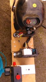
- tank was free, but cost me $20 in fuel to pick it up within two hours of my hobby time.
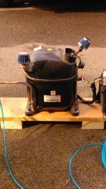
- pump was absolutely free, with a two hour rebuild on hobby time.
- paint ran me about $40.
- hydraulic fittings and hydraulic lines about $100.
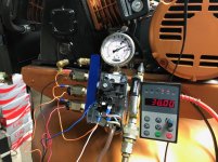
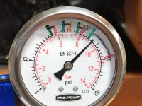
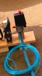
- all new pneumatic fittings, ball valves, pressure gauges $80
- New copper pipe and fittings, $50
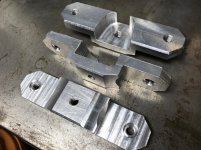
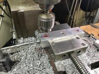
- all metal and aluminum, free, it was in stock
- any bolts or screws, under $10
- stainless steel sheet metal $30
- dehumidifier that I bought at an auction, $.50
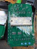
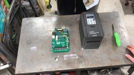
- VFD if purchased $275, but it was in stock.
- repair for the VFD $30(shipping)
- any electrical was in stock or cost me under $10
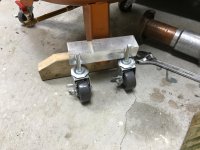
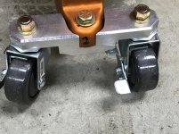
- six casters $100
- New oil, $12
- New automatic drain valve which I'm still waiting for, $14.
- plumbing anti-freeze, $14
And I'm sure there's a few things I've lost count of.

I think I could've done an adequate build for under $100, but I would've had to use an in stock 3 hp Single phase motor. But, then I probably wouldn't of done it.

Somethings I did, wouldn't be required under a compressor rehab, so I'll let you determine the actual price based off my list.

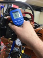
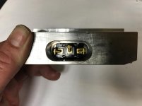
-This compressor has a pre-tank chiller,
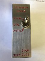
-Runs on a VFD with variable speed,
-I have $100 worth of wheels to make it mobile, And a few other bells and whistles. And I don't think the paint was required.

So far my only regret to this whole project is not replacing the piston rings when I was inside the pump.

Some people just go and buy off-the-shelf and do re-&-re. But I've learned to take another approach.

I am.... Just fixing/building a stupid air compressor. :beer:
 
Last edited:
OP
M

Matt Matt

Well-known member
Joined
May 11, 2017
Messages
523
Location
Ontario
So, here goes a question for guys who really push through air compressor or VFD specialists, Or those who have rotary screw.

I currently have it set up on automatic to...

Charge from empty at 80 gallons 155 psi :
0 to 90 psi= 17 CFM or 140 Hz. Then,
90 to 105 psi= 14 CFM or 90 Hz. Then,
105 to 115 psi= 7 CFM or 60 Hz. Then,
120 to 155 psi= About 5 CFM
I've set this up as my automatic recovery and depletion values for operation.

But,… I'm not finished yet. I want to add in a simple toggle switch on/off/on...to represent hi-Fill (most normal air compressor charges) , Low-Fill (A very "quiet" slow Fill)(for 2 o'clock in the morning tire inflation's, or whatever the reason to run the air compressor). And the auto cycle which was stated above.

My question is, how often do you need high recovery... when you shouldn't be making noise? I think maybe have answered my question. Lol.:lol_hitti
 
Last edited:

oilslick

Well-known member
Joined
Feb 19, 2011
Messages
1,925
Location
Central illinois
Whatever floats your boat! Cool to see others spending time as they see fit, awesome skills! Can't wait for the the next build, whatever it is.
.
 

MacMcMacmac

Well-known member
Joined
Oct 21, 2014
Messages
1,573
Location
canada
You'd be surprised how hot those heads get trying to get 155psi out of a single stage compressor. I'd lower cut-out to around 120psi. You're making more heat than air much higher than that.

This looks like one of the many Fu-Sheng pumps and their knock offs that have taken over most of the low end of the market. I believe the ones with Cast Iron written on them were actually sold by Princess Auto.

https://www.princessauto.com/en/detail/4-7-hp-single-stage-air-compressor-pump/A-p8629495e

8629495.jpg


Be careful how slow you run this pump. Less than 400rpm is getting dodgy for proper splash lubrication, especially for wrist pins.
 
Last edited:
OP
M

Matt Matt

Well-known member
Joined
May 11, 2017
Messages
523
Location
Ontario
You'd be surprised how hot those heads get trying to get 155psi out of a single stage compressor. I'd lower cut-out to around 120psi. You're making more heat than air much higher than that.

This looks like one of the many Fu-Sheng pumps and their knock offs that have taken over most of the low end of the market. I believe the ones with Cast Iron written on them were actually sold by Princess Auto.

https://www.princessauto.com/en/detail/4-7-hp-single-stage-air-compressor-pump/A-p8629495e

8629495.jpg


Be careful how slow you run this pump. Less than 400rpm is getting dodgy for proper splash lubrication, especially for wrist pins.

This is probably been most informative post so far. I do like it!

The only difference between pump head that you have showen, and the pump that I have is: The pump you have shown uses flex reeds, and the one have has floating reeds. The filter seems to be different too.

But after 45 minutes of run time, I'm sitting at 145 psi and, The head temperature has never gone above 175°F. All this testing was done at 38hz, or about 400 RPM pump speed. During the test, The storage tank never drop below 135psi.

I'll try to add some pictures.
 
OP
M

Matt Matt

Well-known member
Joined
May 11, 2017
Messages
523
Location
Ontario
Whatever floats your boat! Cool to see others spending time as they see fit, awesome skills! Can't wait for the the next build, whatever it is.
.
Thanks!, and I probably can't show all my builds at one time,I'd just be here posting, and not building. (And in a few other threads that I have started some people aren't too friendly with 600 V conversion or three phase). i've learned anyone can drag a donkey to the water, but you can't force it to drink.

My hope for this project was to wind this up in six months, doing it as cheap as possible, with minimal purchases. So far, I've been on track.

I have some projects that are in the winds for three years now, but that's another rabbit hole to go down. When you get into some Limited vintage stuff, it becomes a waiting game.
 
Last edited:
OP
M

Matt Matt

Well-known member
Joined
May 11, 2017
Messages
523
Location
Ontario
Here is some pictures of the 45 minute test run at 38 Hz. I was trying to keep the tank bleeding as fast as it was filling between 125 psi and 145 psi. I did a speed check of the pump pulley at 38 Hz. It is 320 RPM. The temperature testing was at the end of the 45 minutes. The pictures are in pretty much chronological order.

Here's a short/walk around video just before it shut down


Attachments

  • IMG_6988.jpg
    IMG_6988.jpg
    141.2 KB · Views: 52
  • IMG_6986.jpg
    IMG_6986.jpg
    128.9 KB · Views: 41
  • IMG_6984.jpg
    IMG_6984.jpg
    128.9 KB · Views: 40
  • IMG_6983.jpg
    IMG_6983.jpg
    129.3 KB · Views: 42
  • IMG_6982.jpg
    IMG_6982.jpg
    141.4 KB · Views: 45
Last edited:
OP
M

Matt Matt

Well-known member
Joined
May 11, 2017
Messages
523
Location
Ontario
So the next part was I wanted to control some of the pressure valves for different recovery speeds.

I started with my half *** electrical drawings and what I wanted to achieve.

I needed a small little box to houses the toggle switch.

So I The cut another chunk of aluminum out of the big plate that's just been sitting around for a few years.

I milled it up to suit it's final position, the way I thought it would make most sense.
 

Attachments

  • IMG_7004.jpg
    IMG_7004.jpg
    139.5 KB · Views: 44
  • IMG_7003.jpg
    IMG_7003.jpg
    134.9 KB · Views: 44
  • IMG_7002.jpg
    IMG_7002.jpg
    133.1 KB · Views: 44
  • IMG_7001.jpg
    IMG_7001.jpg
    136.8 KB · Views: 42
  • IMG_7008.jpg
    IMG_7008.jpg
    131.2 KB · Views: 49
  • IMG_6996.jpg
    IMG_6996.jpg
    133.9 KB · Views: 45
OP
M

Matt Matt

Well-known member
Joined
May 11, 2017
Messages
523
Location
Ontario
The next thing I did is, dry fit the switch and to dry fit it's final location. So far it looks pretty cool to me.

I will still need to add wire trenching and fastening holes/counterbores. And drill and tap for the new bracket/Box. Then I will have to label the switch.

I always need to save something for tomorrow. It gives me something to dream about. And,...it gives me a reason to live for another day!
 

Attachments

  • IMG_7005.jpg
    IMG_7005.jpg
    137.4 KB · Views: 56
  • IMG_7006.jpg
    IMG_7006.jpg
    137.8 KB · Views: 51
  • IMG_7007.jpg
    IMG_7007.jpg
    138.2 KB · Views: 59
Last edited:
OP
M

Matt Matt

Well-known member
Joined
May 11, 2017
Messages
523
Location
Ontario
With the switching block done, i'm going to finish the wiring.
 

Attachments

  • IMG_7015.jpg
    IMG_7015.jpg
    140.9 KB · Views: 73
  • IMG_7014.jpg
    IMG_7014.jpg
    138.4 KB · Views: 67
  • IMG_7013.jpg
    IMG_7013.jpg
    134.1 KB · Views: 50
  • IMG_7011.jpg
    IMG_7011.jpg
    124.7 KB · Views: 50
OP
M

Matt Matt

Well-known member
Joined
May 11, 2017
Messages
523
Location
Ontario
The switch block looks great Matt.

Thanks schor! I actually enjoyed machining the caster feet and the switch block the most out of this whole project.

I made up some motor mount adjusting brackets to take up future slack in poly belt.

I cleaned up the electrical and maybe this weekend I will try out some final operational testing.
 

Attachments

  • IMG_7048.jpg
    IMG_7048.jpg
    145.1 KB · Views: 49
  • IMG_7044.jpg
    IMG_7044.jpg
    145.9 KB · Views: 53
  • IMG_7045.jpg
    IMG_7045.jpg
    140 KB · Views: 46
  • IMG_7047.jpg
    IMG_7047.jpg
    139.8 KB · Views: 47
  • IMG_7041.jpg
    IMG_7041.jpg
    140 KB · Views: 44
  • IMG_7040.jpg
    IMG_7040.jpg
    132.5 KB · Views: 42
  • IMG_7039.jpg
    IMG_7039.jpg
    137.1 KB · Views: 44
Last edited:

MBfreak

MEMBER EMERITUS
Joined
Dec 10, 2010
Messages
2,301
Location
Linkoping , Sweden
MattMatt.

GREAT gumption. Keep it up. Buying stuff only requires money. Repairing, renovating , redesigning and upgrading makes you the TRUE owner.

If you are into books, read Matthew Crawfords Shop Class as Soul Craft.
You must be his cousin:D

Ola
 
OP
M

Matt Matt

Well-known member
Joined
May 11, 2017
Messages
523
Location
Ontario
MattMatt.

GREAT gumption. Keep it up. Buying stuff only requires money. Repairing, renovating , redesigning and upgrading makes you the TRUE owner.

If you are into books, read Matthew Crawfords Shop Class as Soul Craft.
You must be his cousin:D

Ola

I'm not a cousin, and I'm not really into reading books.... thanks for the cheer on.
So I ran The compressor through all the stages and I marked with non-permanent marker for the different hurts trigger switches. After about 4 bleeds and charges, this is what I came up with. Now I just need to adjust the ramping speed and deceleration speeds. The green line represents on for the relay and the red line represents off for the relay. The black line represents The in between of the relay.
 

Attachments

  • IMG_0606.jpg
    IMG_0606.jpg
    134.4 KB · Views: 31

bixxjs

Well-known member
Joined
Jan 22, 2017
Messages
293
Location
United Kingdom
Hi Y'all
Just a few pictures of my own ongoing DIY compressor project.It's based on a cold room refrigerator compressor obviously wired into a 240 volt air pressure switch with an additional manual air pressure dump valve.The air pressure switch is plumbed into an old calor gas bottle.
It still needs wiring up and I will swap the gas bottle for a larger pressure vessel.
 

Attachments

  • IMAG1991.jpg
    IMAG1991.jpg
    151.5 KB · Views: 23
  • IMAG1990.jpg
    IMAG1990.jpg
    154.7 KB · Views: 27
  • IMAG1989.jpg
    IMAG1989.jpg
    151.7 KB · Views: 25
  • IMAG1986.jpg
    IMAG1986.jpg
    154.2 KB · Views: 24
  • IMAG1985.jpg
    IMAG1985.jpg
    145.7 KB · Views: 27
  • IMAG1993.jpg
    IMAG1993.jpg
    154.9 KB · Views: 25
OP
M

Matt Matt

Well-known member
Joined
May 11, 2017
Messages
523
Location
Ontario
Hi Y'all
Just a few pictures of my own ongoing DIY compressor project.It's based on a cold room refrigerator compressor obviously wired into a 240 volt air pressure switch with an additional manual air pressure dump valve.The air pressure switch is plumbed into an old calor gas bottle.
It still needs wiring up and I will swap the gas bottle for a larger pressure vessel.

I look forward to your build thread. How are you relieving head pressure? Are you using a check valve? I am building one of them as well. But I'm going to go somewhat tankless. Have you checked out the max PSI you will be getting off of it? I like your cute little air filters. I will probably be just using a foam roller.
 
Last edited:
To avoid these ads, REGISTER NOW!
Top Bottom