To avoid these ads, REGISTER NOW!

Clausing Mk3a Lathe

hpmachining

Active member
Joined
Aug 12, 2026
Messages
31
Location
Traverse City, Michigan
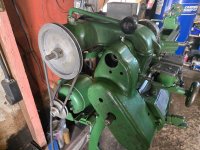
I bought this lathe off Craigslist for $400. Just picked it up yesterday. It seems to be in very good shape, other than the color ;) It might seem a bit ironic, being a self-employed machinist, but I've never owned a lathe before. I should note that I do have experience running a lathe, just haven't owned one. I've been doing a lot of research and reading, but any pointers on getting it setup and running will be greatly appreciated.

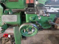
Here is the description from the listing, as well as some pictures.
12 x 36 Clausing Mk3a 100 series metal lathe. Similar to an Atlas 4800.

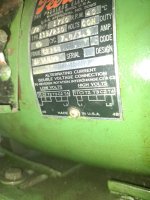
220 volt single phase. Has about 6 foot of cord with a 3 prong male plug.

Power crossfeed, quick change gear box, clutch/ brake, back gear, reversing switch for motor, No.2 morse taper tailstock, No.3 morse taper with 3/4 through hole.

4 jaw independent chuck, 3 jaw scroll chuck, face plate, Jacob's chuck, live center, dead center, rocker tool post and some other miscellaneous items pictured.

This lathe is about 80 yrs. Old. There are some nicks in the ways but it does not appear to have any heavy wear visually. There have been a couple repairs made as pictured. One gear in the quadrant has 2 chipped teeth. These teeth are not consecutive to each other or broke all the way across so there is still constant engagement and does not affect operation.


00u0u_3b4JO2yLYYf_0CI0t2_1200x900.jpg01111_cl7bmQRxPDN_0CI0t2_1200x900.jpg00K0K_5fpCLbEXTqO_0CI0t2_1200x900.jpg00909_aNAkF2swqej_0CI0t2_1200x900.jpg00P0P_3oNZwQxCkUC_0t20CI_1200x900.jpg00w0w_8lav7bngqGR_0CI0t2_1200x900.jpg00D0D_2blU9v9CGwN_0CI0t2_1200x900.jpg00404_2vqke3bYkqI_0CI0t2_1200x900.jpg00808_hDBIGHUoeOj_0t20CI_1200x900.jpg00o0o_4DF8N6iP3PY_0t20CI_1200x900.jpg00202_4GfHN1yFGAK_0t20CI_1200x900.jpg
 
To avoid these ads, REGISTER NOW!

RoninB4

Well-known member
Joined
Jul 22, 2020
Messages
3,749
Location
Under My House
any pointers on getting it setup and running will be greatly appreciated.
-Would begin with a thorough cleaning. Lube all cups and a light coat of oil on ALL machined surfaces including under the tail stock. Keep a light coat of oil on the bed ways. Those chipped gears may give you trouble when single point threading if you plan on that. Would test the headstock for perpendicularity to the bed and test the tail stock spindle axis for being parallel to the bed and being concentric to headstock spindle axis. Clean out and lube the lead screw, there's always chips-n-gunk in them. Inspect all the belts and replace as needed. Check for excess play in the saddle gibs and the cross feed gibs, adjust as needed. There's plenty of stuff you can purchase for the lathe (QC tool post) but that's up to what you want. I would suggest getting a bench grinder for the HSS square bits. Might also suggest making a center setting block/cylinder for easier setting of cutter height. What you plan to do will often dictate what you should do to the lathe and the tooling purchases. What else do you want to know? Looks like it was a decent buy. Congratulations on the addition to the shop.
 
OP
H

hpmachining

Active member
Joined
Aug 12, 2026
Messages
31
Location
Traverse City, Michigan
UPDATE: @mm08822 answered this post in Lighting and Electrical.

Any electricians here that can help me with wiring this lathe for 110V? I think I know what I need to do, but would like someone with more knowledge to check my work. Here is the motor tag:
9ad8db84-8935-43db-93e1-da51c9939737.jpg
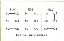
I have an Allen-Bradley 350-TAV32 reversing drum switch with this configuration:
1788469249599.png

Here is what I came up with:
C1 to terminal 3
C2 to terminal 2
[T1 & T2] to terminal 1
[T3 & T4] to terminal 4
L1 to terminal 4
L2 to terminal 6
Jump terminal 5 to terminal 1

I used this video to help me come up with this. Is what I came up with correct?
 
Last edited:
OP
H

hpmachining

Active member
Joined
Aug 12, 2026
Messages
31
Location
Traverse City, Michigan
Thank you for the pointers @RoninB4. I do have a couple bench grinders, as well as a surface grinder. I know tooling will be another rabbit hole. I'll just start out with some HSS square bits to play with and familiarize myself with the lathe. First thing is to get it cleaned up, wired and leveled then go from there. I'll be sure to check those items you mentioned.
 

RoninB4

Well-known member
Joined
Jul 22, 2020
Messages
3,749
Location
Under My House
Thank you for the pointers @RoninB4.
-I hope my suggestions were of some help to you. I've wired a few of my own machines but not confident enough to offer wiring info over the internet and there's more knowledgeable electricians than me here.
I do have a couple bench grinders, as well as a surface grinder.
-Out of curiosity what SG do you have? I find a SG to be almost essential for a lot of projects where parallel/perpendicular or hardened steel is involved.
I'll just start out with some HSS square bits to play with and familiarize myself with the lathe.
-Probably the best route to go. First thing is to determine if the lathe is even capable of running at speeds high enough to utilize carbide. Secondly would be if the lathe is slop/vibration free enough to not chip the cutting edge of carbide. Getting a grinder capable of touching up carbide is on the expensive side. Carbide works well for a lot of things but it's not the panacea most people think it is.
First thing is to get it cleaned up, wired and leveled then go from there. I'll be sure to check those items you mentioned.
-Hope it all works out for you, it's a nice looking model for the age it is.
 
OP
H

hpmachining

Active member
Joined
Aug 12, 2026
Messages
31
Location
Traverse City, Michigan
Last edited:

Firebrick43

Well-known member
Joined
May 12, 2015
Messages
14,483
Location
West central Indiana
To add what has already been recommended, I would recommend replacing the way wipers. I "think" yours are felt and that makes new ones easy to DIY. The last clausing colchester lathe that was rubber I had to draw up and 3D prints some out of TPU.

Also for small light lathes I would recommend getting a pair of LH and RH diamond tangential tools. They are dead simple to grind the HSS bits.


Many home shop machinist try to use carbide inserts from larger machines because they are more common in that setting in the 300 or 400 size and with negative angles. They are way to aggressive for a small lathe without rigidity. Stay away from negative rake tooling even if the idea of double the usable corners sounds appealing. I like the CCMT/CCGT because they build positive rake into the insert.

Screenshot 2026-09-04 092638.png

To supplement the HHS tool holders I would recommend some small CCMT 21.51 insert tool holders are available import in cheap sets for steel and CCGT high hook angle inserts available to use in the same holders for aluminum and brass and don't need high horsepower/rigidity of a large lathe. They are available in 3/8" shank sizes and work well with an AXA tool post on a lathe your size.

AR warner makes HSS inserts for them for even lower cutting forces but I think your lathe will handle the above inserts fine.

 
Last edited:
OP
H

hpmachining

Active member
Joined
Aug 12, 2026
Messages
31
Location
Traverse City, Michigan
Thanks for the feedback, @Firebrick43.
I "think" yours are felt and that makes new ones easy to DIY.
Yes, they are felt. There was even what looks like a new one for the flat ways in with a bag of miscellaneous stuff.

Also for small light lathes I would recommend getting a pair of LH and RH diamond tangential tools.
Those look interesting. I'll check them out when I get things running and start down the tooling rabbit hole. I have a very large selection of tools for milling but practically nothing yet for turning. And yes, I agree with you concerning negative rake inserts. I wouldn't try to use them on something with so little power and rigidity, relatively speaking.

Thanks again for your insights.
 
To avoid these ads, REGISTER NOW!
OP
H

hpmachining

Active member
Joined
Aug 12, 2026
Messages
31
Location
Traverse City, Michigan
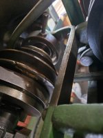
Found my first issue to fix. The clutch doesn't stay engaged. It doesn't pop right back out, but it will after a minute or so of just running the spindle (no cutting yet). It looks like the way it works is when the clutch is engaged, a sleeve with a tapered end slides on the shaft and pushes up a pivoting pin. I believe the rotation of this pin is what locks the spindle pulleys to the shaft. The pin is marked SP1255 on this picture from the manual. It is marked DL 677-S for the entire clutch expander assembly.
1788978554457.png

Red arrow shows the pivoting pin. Clutch disengaged.

20260909_140157_copy.jpg

Clutch Engaged:
1788979080084.jpeg

Damaged area:
1788979141859.jpeg
The sleeve has been damaged on the straight portion, where the pivot pin rests when engaged. It think someone welded it and ground it down by hand to attempt to repair. The pivot pin looks like it has some wear, as well.

Anyone out there with this same style clutch on their lathe? I would like to see a picture of what it is supposed to look like. I don't know if it was just a smooth straight diameter, or if they was a slight "detent" for the pin to rest in. Any feedback appreciated. Thanks for looking!
 
OP
H

hpmachining

Active member
Joined
Aug 12, 2026
Messages
31
Location
Traverse City, Michigan
What do you all think about using these leveling feet for my lathe? There are already holes in the bottom of the legs. It's being set on an epoxied concrete floor that is sloped for a drain. I would put a thicker nut and washer (class 8, maybe?) on the underside and use the nut that comes with it on the top.1789130227132.png
20260911_084611.jpg
 

RoninB4

Well-known member
Joined
Jul 22, 2020
Messages
3,749
Location
Under My House
What do you all think about using these leveling feet for my lathe?
-Should be ok, fairly standard thing to use as machine leveling feet. Leveling a lathe doesn't need to exact like on a surface grinder but I'd put them in if it were my lathe.
There are already holes in the bottom of the legs.
-You sure do want to measure those holes before ordering the feet. Not a lot of fun to open those holes up.
It's being set on an epoxied concrete floor that is sloped for a drain.
-This is where you want to make sure there's rubber on the bottom of those leveling feet. If there's not, the machine vibration will scar the epoxy and/or imprint into the epoxy itself. Lathes are notoriously top heavy so use some caution raising the lathe high enough.
 

Firebrick43

Well-known member
Joined
May 12, 2015
Messages
14,483
Location
West central Indiana
Found my first issue to fix. The clutch doesn't stay engaged. It doesn't pop right back out, but it will after a minute or so of just running the spindle (no cutting yet). It looks like the way it works is when the clutch is engaged, a sleeve with a tapered end slides on the shaft and pushes up a pivoting pin. I believe the rotation of this pin is what locks the spindle pulleys to the shaft. The pin is marked SP1255 on this picture from the manual. It is marked DL 677-S for the entire clutch expander assembly.
1788978554457.png

Red arrow shows the pivoting pin. Clutch disengaged.

20260909_140157_copy.jpg

Clutch Engaged:
1788979080084.jpeg

Damaged area:
1788979141859.jpeg
The sleeve has been damaged on the straight portion, where the pivot pin rests when engaged. It think someone welded it and ground it down by hand to attempt to repair. The pivot pin looks like it has some wear, as well.

Anyone out there with this same style clutch on their lathe? I would like to see a picture of what it is supposed to look like. I don't know if it was just a smooth straight diameter, or if they was a slight "detent" for the pin to rest in. Any feedback appreciated. Thanks for looking!
Have you tried adjusting the clutch via the studs/jamb nuts 180 degrees from the pivot pin 677s?
 
OP
H

hpmachining

Active member
Joined
Aug 12, 2026
Messages
31
Location
Traverse City, Michigan
This is where you want to make sure there's rubber on the bottom of those leveling feet.
Thanks Ronin. The ones I have picked out do have the rubber on the bottom.
Have you tried adjusting the clutch via the studs/jamb nuts 180 degrees from the pivot pin 677s?
No, I haven't. I didn't know that would help hold it in place. I thought that was for adjusting if the clutch was slipping under load, which it doesn't if i hold the lever in place. Do you think that will make it hold the lever in place? I can certainly give that a try. Thank you.
 

Firebrick43

Well-known member
Joined
May 12, 2015
Messages
14,483
Location
West central Indiana
Thanks Ronin. The ones I have picked out do have the rubber on the bottom.

No, I haven't. I didn't know that would help hold it in place. I thought that was for adjusting if the clutch was slipping under load, which it doesn't if i hold the lever in place. Do you think that will make it hold the lever in place? I can certainly give that a try. Thank you.
If you haven't cut much with it you don't know if it is slipping under load?

That is not exactly the most common type of clutch. I had to look at if for a while to see exactly how it actuated. I "think" that you tighten it slightly it may help but keep track of how much you do tighten it so you can set it back if it doesn't work.
 

RoninB4

Well-known member
Joined
Jul 22, 2020
Messages
3,749
Location
Under My House
HP: Since you are working with a sloped floor, you want leveling pads that are like these. They swivel some, and have an elastomer pad on the bottom as well. The come in various stem sizes, diameters and weight limitations.

-The ones he posted both swivel (7-1/2° in the drawing) and have an elastomer pad per his reply in post #17. Might be less expensive at McMaster for the 1/2" existing hole in his lathe legs, there's no threaded stud shown (extra cost?) at MSC.
 

cvairwerks

Well-known member
Joined
Aug 12, 2016
Messages
7,333
Location
Within hearing distance of Texas Motor Speedway
I just pulled that one for example. There are numerous sizes and weight capacities available with other sized thread requirements. With just getting the pads, one can source all thread of the correct size locally and not have to lift the lathe a huge amount to install. No need for a 4+" stud, if you only need a half inch or so. I hate having to lift equipment very high to install stuff. Lift only the minimum height required to do the task.
 
OP
H

hpmachining

Active member
Joined
Aug 12, 2026
Messages
31
Location
Traverse City, Michigan
If you haven't cut much with it you don't know if it is slipping under load?
I did sorta check it. When I tried to take a .030 DOC in 1018 steel, the spindle stalled. My first thought was the clutch slipping, but upon further investigation I found out it was the bull gear lock that was slipping. After tightening it more, it took the .030 DOC easily. I also tried stopping the spindle with the palm of my hand and was unable to. I was easily able to stop it this way when the bull gear lock wasn't tight enough.

No need for a 4+" stud, if you only need a half inch or so.
2" might have been enough, but with the nut and washer stack-up on both sides of the flange and the ~5/8"+ flange thickness, along with the sloped floor, I opted for the longer size to be sure. But the option you suggested in 1/2-13 might still have been an easier way to go.

Might be less expensive at McMaster for the 1/2" existing hole in his lathe legs, there's no threaded stud shown (extra cost?) at MSC.
I ended up getting the same ones I posted from McMaster-Carr at Zoro with a 20% off coupon and free shipping, which saved my a bit over McMaster-Carr. Total cost was $58 for 4.
 
Last edited:
To avoid these ads, REGISTER NOW!
Top Bottom