To avoid these ads, REGISTER NOW!

Compressor after cooler

InterpreDemon

Active member
Joined
May 12, 2015
Messages
27
It looks like a tankless hot water coil from a boiler. Biggest problem I would see is figuring the best orientation for draining the condensate out. Most of those coils spiral out and back in, so if you mounted it vertically with the connections at the bottom you would need a drop stub and drain on both the input and output. They are also designed for fluid/fluid heat exchange and don't need much in the way of fin surface area, so getting enough air around and through that dense pack is a bit more challenging. Not my first choice for a solution, but it can be made to work and would be better than nothing, especially for a smaller compressor.
 
To avoid these ads, REGISTER NOW!

dataman1100

Member
Joined
Dec 30, 2013
Messages
7
Location
Texas
"Let me know how the Hayden 1260 works for you."
The 1200 series are super heavy duty, high volume, nothing like dinky evaporator core coolers. Only units I used on compressors I have modified.
So have your units used been worth it for condensing out the moisture as opposed to any other passive type installation? I.E. Frazinator or Franzinator
 
Last edited:

pcmeiners

Well-known member
Joined
Aug 13, 2009
Messages
7,826
Location
In the only town in Pennsylvania, Bloomsburg.
"Frazinators" use a good bit of energy to drop out moisture, basically works on restriction, air goes from a high pressure to lower pressure to cool air and drop water out; basically same principle as refrigeration which always uses a fair amount of energy.
The 1290 series, properly sized) have non restrictive high flow (minuscule energy loss due to friction), brazed copper pipes (not dinky tubes). they will not self destruct due to vibration, have a aluminum device in the cooling pipes to swirl the air. My setups uses the compressors flywheel for air flow (minuscule HP reduction/cost). Air exiting cooler is ambient temperature, denser. Denser air saves > 10% of the electric cost, drops out enough moisture for most compressed air uses, if equipped with a coalescing filter.
 

404

Well-known member
Joined
Aug 23, 2014
Messages
3,463
Location
Mass
My progress on the hayden 1260 uploadfromtaptalk1442858954582.jpguploadfromtaptalk1442858972695.jpg


Sent from my SAMSUNG-SM-G900A using Tapatalk

Turn that EBM fan around so it blows into the fins for better results.

Even better would be to build a quality sealed air box so no air can bypass the fins, in this case fan in suction is okay, but place fan away from fins by 1/2 the fan diameter.
 

motofool33

Well-known member
Joined
Feb 2, 2013
Messages
1,634
Location
Currently North of Houston
Turn that EBM fan around so it blows into the fins for better results.

Even better would be to build a quality sealed air box so no air can bypass the fins, in this case fan in suction is okay, but place fan away from fins by 1/2 the fan diameter.
From spinning it by hand the flow is towards the fins. But I haven't got power to it yet to test.

Sent from my SAMSUNG-SM-G900A using Tapatalk
 

404

Well-known member
Joined
Aug 23, 2014
Messages
3,463
Location
Mass
From spinning it by hand the flow is towards the fins. But I haven't got power to it yet to test.

Sent from my SAMSUNG-SM-G900A using Tapatalk

That would be the first I have seen blowing that way. Not impossible of course, but I would be really surprised. All the ones I have seen blow through the grating.
 

motofool33

Well-known member
Joined
Feb 2, 2013
Messages
1,634
Location
Currently North of Houston

inline five

Well-known member
Joined
Dec 22, 2014
Messages
125
Location
Raleigh, NC
I have this 1/2"copper in a double spiraled loop with fins
28vbvk2.jpg

which would probably work great, but I really don't know If I need to even bother. It's a IR2475 80gal with a 40gal surge tank. We get very little water in our system as it sit now. Maybe a 8oz of water a day during hard use out of the main tank, and less then 1oz at the sharpe filter which is mount down stream off 18' of 1" black iron pipe

The big question is should I even bother with the headache of plumbing all of this in? The compressor came with a factory intercooler which works but is probably lacking.

Options or ideas....

That would be fantastic for painting. Put it in a bucket of ice water after running it out of the tank, put a filter out the end and run the air hose to your gun...
 

404

Well-known member
Joined
Aug 23, 2014
Messages
3,463
Location
Mass
I have this 1/2"copper in a double spiraled loop with fins
28vbvk2.jpg

which would probably work great, but I really don't know If I need to even bother. It's a IR2475 80gal with a 40gal surge tank. We get very little water in our system as it sit now. Maybe a 8oz of water a day during hard use out of the main tank, and less then 1oz at the sharpe filter which is mount down stream off 18' of 1" black iron pipe

The big question is should I even bother with the headache of plumbing all of this in? The compressor came with a factory intercooler which works but is probably lacking.

Options or ideas....

That coil is out of a
Amtrol- Boilermate


And may not be rated for the air pressure you will have. Blowing air over it, or putting it in a big bucket of water, will improve the performance.


Good luck.:thumbup:
 

Finky198

Well-known member
Joined
Feb 25, 2014
Messages
2,120
Location
North East
I was thinking for painting and the plasma cutter it would be great says it's rated up to 125 psi of working pressure. Now that you mentions it I might make something with a 5 gallon and plumb in a reg/filter and two out puts And then I can just add water and ice when needed

Thanks guys this is exactly why I like GJ so much...
 
Last edited:

motofool33

Well-known member
Joined
Feb 2, 2013
Messages
1,634
Location
Currently North of Houston
So I'm looking for some help on wiring my EBM Pabst fan


EBM Papst W2E300-CC47-57 230V 50Hz/0.62A/140W/2650 60Hz/200W/2900 AC Axial Fan

https://www.google.com/url?sa=t&sou...bOgAxE&usg=AFQjCNEv2A0xDpRy_oG5WH_yyGzadB6mdw

On page 416 is the electrical diagram
I'm not an electrician but what is the c and why is z connected through it. (Pic attached of diagram)
uploadfromtaptalk1443640290716.jpg


My plan is to have it hard wired to the motor so when motor starts fan also starts.


b191554fa60812f63199831e527444a8.jpg

Appreciate any help

Sent from my SAMSUNG-SM-G900A using Tapatalk
 

Attachments

  • uploadfromtaptalk1443640290716.jpg
    uploadfromtaptalk1443640290716.jpg
    8.4 KB · Views: 1,029

lametec

Well-known member
Joined
May 5, 2008
Messages
2,099
Location
Michigan

motofool33

Well-known member
Joined
Feb 2, 2013
Messages
1,634
Location
Currently North of Houston
The C is a run capacitor. Without it the fan won't turn. Looks like you ordered a fan without a built-in run capacitor, so you'll have to get one. You'll need a 5uF/400V AC run capacitor according to the spec sheet.

Here's a capacitor that should work: http://www.ebay.com/itm/151824949571
Or one from Amazon (cheaper than ebay if you have prime): http://www.amazon.com/dp/B00A76L3WG/?tag=atomicindus08-20
Thanks a bunch for that, now since we're on a roll where would you recommend I wire this in?


f60f707cc81fbab2c4844bdc410835b4.jpga0b41142ebf0fd71d9825c8645d4232d.jpg

Sent from my SAMSUNG-SM-G900A using Tapatalk
 

shoot summ

Well-known member
Joined
Jun 8, 2010
Messages
2,948
Great thread, I went through it when I replaced my pump, really wanted to go the cooler/fan route put went a different direction.

Made my own "cooler" out of 8' of copper pipe, mounted it so the compressor fan pulls air across it. Makes a noticeable difference in air temp, and I get a LOT of water out of the drop leg drain.

B2F5D3B0-6AD1-4A73-BEF5-84FE9F2DE6A2_zpsbaprujs6.jpg
 

lametec

Well-known member
Joined
May 5, 2008
Messages
2,099
Location
Michigan
Thanks a bunch for that, now since we're on a roll where would you recommend I wire this in?


For your compressor, I wouldn't wire it in at all. The noise from the compressor will drown out the noise from the fan, and I can't see a reason for wanting less airflow over your cooler.

As for how to wire it, I'm not sure. I couldn't find any diagrams showing 2 reds and a green wire for that controller.
 
To avoid these ads, REGISTER NOW!

motofool33

Well-known member
Joined
Feb 2, 2013
Messages
1,634
Location
Currently North of Houston
For your compressor, I wouldn't wire it in at all. The noise from the compressor will drown out the noise from the fan, and I can't see a reason for wanting less airflow over your cooler.

As for how to wire it, I'm not sure. I couldn't find any diagrams showing 2 reds and a green wire for that controller.
I'll try just hard wiring fan at first after the capacitor gets here saturday. I can't imagine this compressor being louder then the 1500cfm fan at 78db. But hopefully

Sent from my SAMSUNG-SM-G900A using Tapatalk
 

404

Well-known member
Joined
Aug 23, 2014
Messages
3,463
Location
Mass
There is no room to put the run capacitor internally on those, so they do not have a built in capacitor.

The good news is that one can put the cap far from the fan if need be.
 

lametec

Well-known member
Joined
May 5, 2008
Messages
2,099
Location
Michigan
Is all that stuff (switch, filter, reg, and hose) just hanging off the outlet pipe with no other support? You're looking at a fatigue break one of these days if it's not supported.

Personally I'd connect the switch to the tank using a shorter pipe (******), then a hose to the filter and regulator which would be mounted on the wall.
 

motofool33

Well-known member
Joined
Feb 2, 2013
Messages
1,634
Location
Currently North of Houston
Is all that stuff (switch, filter, reg, and hose) just hanging off the outlet pipe with no other support? You're looking at a fatigue break one of these days if it's not supported.

Personally I'd connect the switch to the tank using a shorter pipe (******), then a hose to the filter and regulator which would be mounted on the wall.
It's all gonna get changed as I put in the quincy compressor shortly. All that is temporary solution.

Thanks for the input on it duely noted.

Sent from my SAMSUNG-SM-G900A using Tapatalk
 
Last edited:

404

Well-known member
Joined
Aug 23, 2014
Messages
3,463
Location
Mass
When you do the final version, make a plenum so air is forced/ducted thru the entire area of the heat exchanger. Right now looks like you are only blowing on the top area. Any air that bypasses is wasted.

If you do the plenum the airflow thru the heat exchanger will be more even if you **** air out of the plenum. Keep the HX 1/2 fan diameter away from the fan.
 

TNToy

Well-known member
Joined
Oct 11, 2006
Messages
1,385
Location
West Tennessee
I had been posting this in a separate thread, but now that I'm getting ready to begin actually building the after cooler I thought I'd move over here to make it easy for others to find all of these builds in one place.

I'm using a TruCool H7B oil cooler, which is a pretty substantial unit at 11" x 11.5". It cost $75 shipped. Plumbing will consist of 3/8" SAE 100R2 hydraulic hose, rated for 4750 psi and 280 degrees continuous. I'll upgrade if that hose can't take the heat, but it's readily available from work so I'm giving it a shot.

Here's what I accomplished tonight. Began fabricating a removeable bracket to mount the cooler which attaches through existing holes in the top of the tank. It'll hold the cooler 1/4" away from the plastic cowling over the fan built into the pump's pulley. The slope built into the bracket is obviously intentional to make sure no water puddles in the bottom of the cooler after the compressor shuts off.
 

Attachments

  • image.jpg
    image.jpg
    15.8 KB · Views: 313
Last edited:

TNToy

Well-known member
Joined
Oct 11, 2006
Messages
1,385
Location
West Tennessee
I expect to see 250-300* air entering the cooler, and a temperature very close to ambient exiting. Almost everyone has built one of these with a piggybacked electric fan, however I plan to try to utilize the airflow through the pump's pulley.

I'll run it for 10mins continuous in factory form, first.

Then 10mins with the cooler added.

Then 10mins with the cooler blasted with a high-output 110v fan. If the fan is a noticeable help, we will finally know for certain. And I'll install one.

I'll have this finished in a couple of days, and I will post back-to-back results with an infrared temp gun aimed at the pump outlet, cooler in/out ports, and the tank fitting.
 
Last edited:

TNToy

Well-known member
Joined
Oct 11, 2006
Messages
1,385
Location
West Tennessee
Sure thing! I love seeing things like that posted by others. Figure I might as well return the favor.

My compressor is one of the cheapest 220v uprights you'll find, and being single stage it runs very hot and is rather loud. I was actually in the market for a 110v unit until I saw this one for sale as an open box item with scratches down the side of the tank for $366. I couldn't pass that up.

The one benefit to this cheap single stage unit is the amount of airflow through the pulley/fan. It spins a lot faster than a two-stage Quincy, has six steeply pitched blades, and there is a VERY tight fitting shroud around both the intake side of the fan, and the head of the compressor on its exhaust side. A lot of air moves across that cylinder head when it is operating, much more than on the cooler-running industrial units at work.
 
Last edited:

TNToy

Well-known member
Joined
Oct 11, 2006
Messages
1,385
Location
West Tennessee
Built and painted my bracket to position the aftercooler:

1) Where it would get maximum airflow from the fan
2) 3/16" away from the plastic drive belt housing
3) on enough of a slant toward the discharge hose to ensure drainage
 

Attachments

  • IMG_0080.JPG
    IMG_0080.JPG
    73.3 KB · Views: 195
  • IMG_0079.JPG
    IMG_0079.JPG
    77.4 KB · Views: 193
  • IMG_0075.JPG
    IMG_0075.JPG
    141.4 KB · Views: 191
  • IMG_0081.JPG
    IMG_0081.JPG
    70.2 KB · Views: 204

TNToy

Well-known member
Joined
Oct 11, 2006
Messages
1,385
Location
West Tennessee
I ran the compressor in unmodified form last night as well. Ambient temp in the garage was 55 degrees, and I recorded operating temps at 5 minutes and 10 minutes, throttling the ball valve on the side of the tank so that it held right at 100psi for the duration of the test.

After 10 minutes I was seeing around 290* at the compressor head, about 160-190 entering into the tank, and the tank itself measured around 125* at its warmest point.

(I'll post the exact measurements when I have tested the aftercooler, side by side.

I have to say that I don't expect an auxiliary fan to be needed - because the fan is so tightly shrouded around the compressor head and around the fan's intake... it moves enough air to easily keep a nitrile glove very firmly sucked against the cooler. Hopefully that means it moves enough air - I'd like to be done with this project and ready to tear into a Durango which needs a trans rebuild and a paint job.
 

Attachments

  • IMG_0078.JPG
    IMG_0078.JPG
    79.1 KB · Views: 137
  • IMG_0082.JPG
    IMG_0082.JPG
    101 KB · Views: 144
  • IMG_0088.JPG
    IMG_0088.JPG
    79.1 KB · Views: 149
  • IMG_0076.JPG
    IMG_0076.JPG
    75.1 KB · Views: 151
Last edited:

TNToy

Well-known member
Joined
Oct 11, 2006
Messages
1,385
Location
West Tennessee
Finished this project this weekend and used the compressor for a while as well. I'm quite happy.

First thing I did was build a baby franzinator-type water separator with about $12 worth of fittings from the local plumbing supply. The first photo shows me trimming down a 90 degree 3/8" elbow so that it would fit into the main body, which is 1.5" OD.

Rather than use pipe dope or teflon to try to seal the large end caps, I used an industrial-grade epoxy. It passed the soapy water test just fine. No bubbles.
 

Attachments

  • compfinished04.5.JPG
    compfinished04.5.JPG
    94.7 KB · Views: 221
  • compfinished03.JPG
    compfinished03.JPG
    140.6 KB · Views: 187
  • compfinished02.JPG
    compfinished02.JPG
    77.8 KB · Views: 178
  • compfinished01.JPG
    compfinished01.JPG
    132.7 KB · Views: 201
Last edited:

TNToy

Well-known member
Joined
Oct 11, 2006
Messages
1,385
Location
West Tennessee
Then I modified the hardline from the compressor head to the tank to connect to hydraulic hose (3/8" compression fitting to 1/4" NPT) and then I finished plumbing the entire cooler/separator assembly. I managed to keep everything sloped downhill from the cylinder head all the way to the separator.

Sorry about the Dillon 650 reloading press in the background.
 

Attachments

  • compfinished06.JPG
    compfinished06.JPG
    83.8 KB · Views: 293
  • compfinished04.jpg
    compfinished04.jpg
    58.4 KB · Views: 236
  • compfinished05.JPG
    compfinished05.JPG
    94 KB · Views: 237
Last edited:

TNToy

Well-known member
Joined
Oct 11, 2006
Messages
1,385
Location
West Tennessee
And now for the finale...

It works. Really damn well.

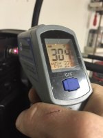
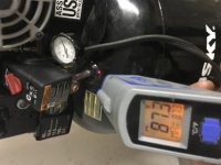
These photos are after running it for 10 minutes straight at 100psi. It looks like I did increase the pump temperature by around 20 degrees because I'm sucking air through a warm cooler before running it across the compressor head.

(By the way, shop temps were around 55-60 degrees for BOTH tests. It wasn't a hot day here in the South at all.)

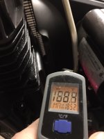
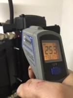
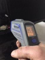
Temperatures dropped by 230+ degrees between the compressor head and the exit of the oil cooler, and then stayed fairly stable, with the tank holding less than 20 degrees above ambient during the full-blast test.

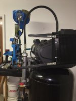
Lots of water in the mini-Franzinator, a bit in the tank. Dry air coming out of a hose plumbed directly into the side of the tank without any filters or separators (which I will be adding anyway, since I plan to paint with this setup!)

The unloader valve does hiss much longer / louder now that it has to depressurize the cooler and the water trap - it airs down for exactly 11 seconds after the pressure switch opens. But I really like having the separator / Franzinator Jr where it is - once the unloader pops off, I can simply drain the accumulated water without it blasting all over the floor. I'll be able to keep a small bucket underneath it and just twist the ball valve open every once in a while, as well as leaving it open to help keep the separator clean inside between uses of the compressor, without totally dumping the air out of the tank.

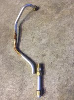
Now I can fix two small air leaks that I found during testing, and clean the pipe assembly up and shoot it with gloss black to match the tank.
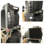
Photo 1: Pump exit
Photo 2: Cooler in
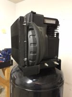
Photo 3: Cooler exit
Photo 4: Tank temp
 

Attachments

  • compfinished09.JPG
    compfinished09.JPG
    70.9 KB · Views: 118
  • compfinished10.JPG
    compfinished10.JPG
    63.4 KB · Views: 119
  • compfinished11.JPG
    compfinished11.JPG
    65.7 KB · Views: 129
  • image.jpg
    image.jpg
    16.5 KB · Views: 111
Last edited:

TNToy

Well-known member
Joined
Oct 11, 2006
Messages
1,385
Location
West Tennessee
...because I accidentally posted the photo from the first test, before installing the cooler. Fixed, thanks! (Tank was 87 degrees)
 
To avoid these ads, REGISTER NOW!
Top Bottom