To avoid these ads, REGISTER NOW!

converting a 3 phase welder to single phase.

blue dog

Banned
Joined
Jul 4, 2010
Messages
4,051
Location
Culver City Ca.
I found a miller cp200 welder in perfect condition with very little time on the machine, for very cheap price. problem is that it is a 3 phase machine, i only have single phase 220 available.
So, is it possible to convert this machine to single phase ? if possible, will it effect the duty cycle ? or weld capability ?
Am i wasting my time and effort ?
 
To avoid these ads, REGISTER NOW!

coldfusion21

Well-known member
Joined
Jul 7, 2005
Messages
404
Location
portland, oregon
I found a miller cp200 welder in perfect condition with very little time on the machine, for very cheap price. problem is that it is a 3 phase machine, i only have single phase 220 available.
So, is it possible to convert this machine to single phase ? if possible, will it effect the duty cycle ? or weld capability ?
Am i wasting my time and effort ?

I don't think it's possible, unless the machine is designed to be run on either single or three phase.

I've found ( and been told) there's a reason 3 phase welders are generally cheap used. I looked into adding 3 phase service but couldn't justify the expense.
 

gte718p

Well-known member
Joined
Mar 12, 2009
Messages
3,950
Not possible to convert the machine. It may be possible to run it off a rotatary phase converter. That works okay for mills and lathes, but generally it is not reasonable to build a phase converter big enough to deal with the start current of a welder.

The cheapest option is generally to buy a mil surplus 3 phase generator.

As cold fusion said there is a reason they are cheap.
 
OP
B

blue dog

Banned
Joined
Jul 4, 2010
Messages
4,051
Location
Culver City Ca.
OP
B

blue dog

Banned
Joined
Jul 4, 2010
Messages
4,051
Location
Culver City Ca.
Actually, it is VERY affordable if you follow the link BigMike posted.

You had better be comfortable working with BIG power :shocking: but it is doable.

Not so comfortable with the big power part. The taste of copper does not agree with me. But i agree, it is doable, and has been done.
 

eriksalo

Well-known member
Joined
Nov 29, 2007
Messages
184
Location
Colorado
I have worked with some people who have tried this. I have also constructed from scratch a 3 phase rotary converter for my milling machine so I know the in's and out's of working with 1-3 phase power pretty well (I'm also an electrical engineer but that's not as useful as you might think). It's not "theoretically" possible to generate true 3 phase power but in practice you can make it work in some applications. My overall comment is it isn't worth the trouble for a welder.

Here's the problem: Three phase power has just that, three phases. In the three phase power from your utility, there's 60Hz ac power in each of the three phases. This is generated from a huge motor at the power plant. The power is 120 degrees apart in each phase (120+120+120 = 360 degrees). "Regular" 220 power is generally referred to as "single phase" but I've never understood why, it should be called "2 phase" since each line carries 110V and the two lines are exactly out of phase with each other (180 degrees since 180+180=360). When both phases are at max (one negative and one positive), each is 110 volts from zero so they differ by 220 volts.

Making 3 phase power from "single phase" power is theoretically impossible without something like FET's or IGBT's. Generating three phase power is theoretically impossible since the single phase output is ALWAYS going to be 180 degrees apart. The best you can do is to have two of the phases 180 degrees apart and then make a third phase in the middle. The way you do this is to run single phase power to a 3 phase electric motor. A 3 phase motor will start and run on single phase power (with about half the output). When that 3 phase motor is spinning, magnetic flux movement in the motor induces the third phase. You also need lots of capacitors in the system to "store" the power for the third phase. It's not trivial but can be done well if you take some time to tune the phase legs to similar voltages.

The only way to make real (but not actually perfect) 3 phase power is to use a big, fast switching set of transistors (like FET's or IGBT's), feed them AC power converted to DC and then have the transistor switch on and off really fast to simulate a sine waves 120 degrees apart. The new inverter type welders essentially do this. Motor controllers for things like electric and hybrid cars do this, make pretty close to real three phase power from DC input using fast switching transistors.

In practice, most motors run fine on generated 3 phase power. This is also true for the stepper motors in CNC milling machines, etc. However, my friends and I have had bad luck with welders. The Dave Kamp article shows some artful work but you still aren't getting real 3 phase power. One friend has a 3 phase Hobart we've just never been able to get to run right on even the very best generated 3 phase power.

If it were me, I would skip this project and get one of the better Chinese inverter welders (no spam please, I've done lots of research, burned lots of rod and own half a dozen welders ranging from a 1969 300 Amp Idealarc TIG to a new Everlast inverter). The new Chinese welders aren't as good as a Miller but they are pretty darn good. The inverter technology will allow you significant arc freedom and there's nothing better for Aluminum.

If you are going to do steel TIG or ARC welding, then there's nothing like one of the old single phase transformer based welders (they are big, my old Idealarc 300/300 weighs 900 lbs). Arc is beautiful and stable with lots of adjustability. Many people say the new inverters are just as good and maybe they are but they don't feel as good to me.

I hope this was a helpful comment.
 

markw365

Well-known member
Joined
Aug 16, 2011
Messages
207
This is pretty funny. My uncle was just telling me he converted a 3 phase miller machine, cost about 50 bucks. He also referred to a thread on practical machinst. I'll have to forward him this. It wasn't two hours ago we were talking about his new welder.
 

theoldwizard1

Well-known member
Joined
Feb 22, 2011
Messages
43,073
Location
SE MI
The best you can do is to have two of the phases 180 degrees apart and then make a third phase in the middle.
That is exactly what they are doing !

Using some big motor-run caps that they found cheap. There is a Miller CP-200 for sale on CL not too far for $400. The caps and wire should be less than $150. No Chinese unit could touch that price.
 

Roots

Well-known member
Joined
Oct 31, 2010
Messages
1,788
Actually, it is VERY affordable if you follow the link BigMike posted.

You had better be comfortable working with BIG power :shocking: but it is doable.

Well that's a very interesting read! :beer: Much different than what I had in mind!
 

lametec

Well-known member
Joined
May 5, 2008
Messages
2,099
Location
Michigan
A bit off topic, but OP seems to have made up his mind as to what to do about the welder, so....

In the three phase power from your utility, there's 60Hz ac power in each of the three phases. This is generated from a huge motor at the power plant. The power is 120 degrees apart in each phase (120+120+120 = 360 degrees).

Correct.

"Regular" 220 power is generally referred to as "single phase" but I've never understood why, it should be called "2 phase" since each line carries 110V and the two lines are exactly out of phase with each other (180 degrees since 180+180=360).

If it's two phases, how can they be 180° out? You just said (correctly) that the 3 phases are 120° apart. So if "single phase" is really two of those phases, they have to be 120° apart, not 180°.

The reason it's called single phase is that the 240V is taken off of one of the 3 phase lines. The transformer that supplies 240V is connected between one of the 3 phase lines and ground. This transformer has 3 output taps on it. Between the two outer taps, you have 240V. Between either of the two outer taps and the center taps, you have 120V.

And this is why it's called single phase. It comes off a single phase of the 3-phase set. It's also (more correctly) known as "split phase", which makes sense, since the single incoming phase is split into two 120V "phases", 180° apart.
 

theoldwizard1

Well-known member
Joined
Feb 22, 2011
Messages
43,073
Location
SE MI
If it's two phases, how can they be 180° out?
First normal house wiring is not two phase it is split phase.

The input side of the welders transformers has 3 separate windings. L1 and L2 are the 2 "hots" coming in (240V). The first set of windings is wire L1L2. The second set of windings is also wired L1L2 but there are some BIG capacitors placed on each input leg which causes an approximate 90° phase shift. The third set of windings is wired L2L1. Because they bare reversed, it is 180° out of phase with the first set of windings.

If you read the entire thread on the Miller CP-250TS conversion, it was not a complete success because there appears to be something else wrong with the machine (it was never tested before conversion).

However, the author if the thread also converted a Miller CP-200 a while ago and it was tested good !

BEFORE

20756d1267790033-miller-cp200-converted-240v-single-phase-cp200-before.jpg


AFTER

20757d1267790586-miller-cp200-converted-240v-single-phase-peters-miller-solution.jpg


The capacitors are 60uf 400v motor-run capacitors. 60uf 370V (close enough) caps are about $15 each on eBay. $30 in caps. Resistors are a couple of bucks each. The rest is wire, connectors and plug.
 
Last edited:

eriksalo

Well-known member
Joined
Nov 29, 2007
Messages
184
Location
Colorado
Hi lamtec;

I agree you are exactly correct in your above note. I think the residential grid in the US is technically called a "three wire - single phase - midpoint neutral" system. Now and then (mostly in the older parts of the country) you can still find High-leg delta systems (they enable pulling a single phase out of a 3 phase system with a center tapped delta transformer) but they are becoming a thing of the past.

My point is that for our residential 220V supply (e.g. what you get in your garage) you have two hot wires and the potential voltage from ground of one is 180 degrees out of phase with the potential voltage from ground of the other. Specifically, this means that when one is max negative, the other is max positive and when one is zero, the other is zero. This is of course generated by the transformer on your utility pole and the source of the power is a single 220V phase from the plant.

While you are totally correct that the power we get is a "single" one of the three phase from the plant, in explaining three phase converters to people I've always had better luck articulating it as above and showing "two phases" coming from the pole and the third "phase" being generated by the phase converter.

If I hook an o-scope up to the wall outlet, it's easy to see the relation between the hot wires. You can still see that same power after the the phase converter with the o-scope with the third phase added.

The main point for welders is (in my limited experience) the three phase you "approximate" doesn't result in great welding performance. If you take an old 3 phase transformer welder that's been converted to run on single phase, it will not give you as nice of an arc. I've done this a few times (run welder X on real 3 phase and then run that same welder on power generated from single phase) and it's just not as good. In the few samples we've tried the welder works but the arc just isn't right. YMMV of course, this has just been my experience.
 

lametec

Well-known member
Joined
May 5, 2008
Messages
2,099
Location
Michigan
eriksalo: I had a feeling you knew what you were talking about, but since you said you never understood why it's called single phase, I expounded on the topic a bit.

The technical term for the two "phases" in a 240V system is legs.

But anyway, seems like we all know what's going on, so no need to go further off topic. :)
 

mrb

Well-known member
Joined
Dec 31, 2008
Messages
3,734
dangit.. i have 3ph but not an extra $700 sitting around i can spend on a welder.
 

theoldwizard1

Well-known member
Joined
Feb 22, 2011
Messages
43,073
Location
SE MI
The main point for welders is (in my limited experience) the three phase you "approximate" doesn't result in great welding performance. If you take an old 3 phase transformer welder that's been converted to run on single phase, it will not give you as nice of an arc. I've done this a few times (run welder X on real 3 phase and then run that same welder on power generated from single phase) and it's just not as good. In the few samples we've tried the welder works but the arc just isn't right. YMMV of course, this has just been my experience.

Some people will disagree with you.


And here
 
To avoid these ads, REGISTER NOW!

eriksalo

Well-known member
Joined
Nov 29, 2007
Messages
184
Location
Colorado
It does look like some people have had good luck running their 3 phase welders on single phase power. That's terrific. Sadly, it hasn't worked very well for me.

I notice that the successful projects cited have been on Miller CP200's so maybe that welder is a better candidate. I've not tried on a CP200.

My experience is with a Lincoln Idealarc, a Airco and two Hobarts. The Lincoln and the Airco did better than the Hobarts. For some reason the Hobart's had a really bad arc but none of the welders ran that great on single phase.

When all was said and done, I traded the two hobart's for an old single phase Idealarc. Smoothest arc of any welder I've ever used, built in 1969 and I still TIG with it all the time. Like "buttah!"
 

DaveKamp

Member
Joined
Sep 16, 2011
Messages
8
Hi Guys-

Someone forwarded a link to this thread, and told me to check it out, so I did...

Sorry about not having updated the CP-250TS thread for a while- my company has been inundated with projects for the last year, so I haven't gotten much shop time. The CP250TS is a very 'early' design in terms of wire-feed history, and uses separate 'slump reactor' coils for each of the three legs, adjustable to suit the variables which welding engineers didn't quite have a handle on. The TS was intended for high-power spray welding with thick wire, so it needs additional output inductance to 'calm down'. I haven't done anything else with mine since last year, but will when winter comes on.

I'm pretty sure my email address is posted on the PM forum- if you want to know answers, all 'ya hafta do is ask...
 

sberry

Banned
Joined
Jun 18, 2005
Messages
35,747
Location
Brethren, Michigan
There is some great info in this thread, I should build or buy a converter one of these days but in reality just another piece of equipment laying around and another step to use something.
As a practical matter,,, for most people, small shops it really isn't worth all the fukkin around and depending on the need, size wise new feeders especially in the 180-210 class are so affordable anymore brand new for my money it just plain wouldn't be worth the effort, and they work well, extremely well, super suited to hobby, garage, automotive type stuff. They run on 20-30A service, weld with it all month and never notice a bump in the bill. They use light extension cords if needed, are easy to move, are even easy to sell if needed sometimes bringing almost as much as when they were new.
The little Lincoln has hundreds of hours on it,,, seen service wayyyyy beyond what any hobby shop would ever give it.
 

Attachments

  • Hobart cart.JPG
    Hobart cart.JPG
    52.6 KB · Views: 25
  • SP cart 2.JPG
    SP cart 2.JPG
    63.8 KB · Views: 36
Last edited:

DaveKamp

Member
Joined
Sep 16, 2011
Messages
8
Generating three phase power is theoretically impossible since the single phase output is ALWAYS going to be 180 degrees apart. The best you can do is to have two of the phases 180 degrees apart and then make a third phase in the middle.

Hi Eric!

Don't glue yourself into theory... What you have here, is a statement that seems logical, but in reality, it is NOT correct. When you build a rotary converter, you actually DO generate three phases, and they're very close to 120 degrees apart, but the phase relationship will vary slightly based on change of output load and line frequency.

The reason: When you load a rotary phase converter, you're not using the neutral lead... it is irrelevant.

The neutral centerpoint is in the I realm- it is there, but although there is no physical 'neutral', like what you'd expect out of a 240v Y-wired generator, but the output is genuine, bona-fide true three-phase 120-degree power less a few degrees of skew on balance of XC and XL. The finite details of the explanation appear in the Fitch-Williams white paper.

Imagine it this way. Put two dots on a piece of paper... 2.4 inches apart. Mark the centerpoint, and draw a line going straight up. Now take your compass, set it to the 2.4" radius, land the spike on one dot, and find the point where the radius crosses your vertical mark. Repeat for the other point. Put a third point at that three-way intersection.

Your UTILITY NEUTRAL point is where the horizontal and vertical lines intersect.

Your TRUE NEUTRAL point occurs slightly up that vertical line a ways.

Regardless, it doesn't matter to an electric motor, as long as you're fairly close.


But I wouldn't run a 3-phase welder off a rotary converter... it's simply not necessary. Phase-shifting the center leg of the welding transformer is a whole lot more 'stiff' when welding at higher power levels, and you don't have that 'other' gadget running, and the extra 3-phase extension cord hanging around and limiting your reach.

As for comparing the utility of an industrial-grade machine against a portable lunchbox welder, that's a pretty poor comparison, and I didn't develop this conversion to pit the two, as it's like riding a moped to Sturgis.

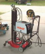
I've used Century, Lincoln, Miller, and even imported lunchbox MIGs, and own an original Hobart Handler (made in like... '87?) that I use all the time, and I even put it in my service truck and take it along on jobs when I need to squirt wire to tack parts together in-situ, where a stick isn't practical. I would NOT, however, trade my Handler, or even consider using it for anything other than extremely light work. Why? Duty cycle and output. Very few lunchbox welders have duty ratings over 25%... they simply don't have enough iron in the transformer core, and many use aluminum windings to reduce package weight (portability).

Look at this one:
http://www.lincolnelectric.com/en-us/Equipment/Pages/product.aspx?product=K2471-1#target2

20% duty cycle @ 90A. $600.

Now look at what they rate as more of a 'commercial' or 'light industrial':

http://www.lincolnelectric.com/en-us/Equipment/Pages/product.aspx?product=K2701-2

A little better... 40% @ 250. $2800.


Now read the ratings of a Miller CP-200...

100% @ 200A. Typical Price: $400 or so (including some capacitors).

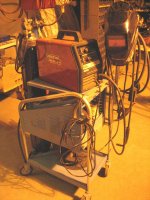
Pocket welders have their place. The reason I did this, and other conversions, is because there's a whole WORLD of superior machines- real industrial machines... out there, available for literally PENNIES on the dollar... and many times, FREE. (yep, my favorite four-letter F-word)

As far as the 'trouble' and 'f-ing around', well, if you're taking time to work on things, and you want to learn a few things, and see the DIRECT RESULT of learning and dilligent effort, have at it, and enjoy the fruits of my labor... many have (I get calls and questions every couple weeks, and only a scant few are actually engineers, technicians, or electricians)... and my general attitude always applies- If it doesn't seem to 'work', I'll volley emails and phone calls to help solve the problems... 'cause it ain't that difficult.

If someone's not interested, or have no need for a really powerful, really sweet, and really inexpensive welder, it doesn't break my heart. I have no pecuniary interest in someone else's success here, and I don't sell anything. This project is very simple: I was faced with a personal challenge, came up with an idea, invested my time and effort to make it work, then I published the results of my work. I owe credit and a big thank-you to Peter Haas, formerly of PG&E for his efforts double-checking my math and concepts. I then released it into the wild for the benefit of any and all, with a promise that it really DOES work... so consider it worth AT LEAST, and if you try it, MORE than what you paid for. I kinda doubt you'd find a better deal anywhere.
 

DaveKamp

Member
Joined
Sep 16, 2011
Messages
8
Oh- I like the lawnmower deck re-use. I'd rather have steel than plastic wheels, but use what' ya got. My Handler came to me on a butchered-up shopping cart, but I run it hand-portable on fluxcore now. If I'm workin' a job where I hafta shuffle it around, I strap it to an old handcart used for moving golf-bags.
 
OP
B

blue dog

Banned
Joined
Jul 4, 2010
Messages
4,051
Location
Culver City Ca.
I moved on since originally starting this thread, why? because i found this on craigslist.
 

Attachments

  • IMG_1267.jpg
    IMG_1267.jpg
    142.3 KB · Views: 53

eriksalo

Well-known member
Joined
Nov 29, 2007
Messages
184
Location
Colorado
Hi Dave;

This is a really terrific note, thanks for taking the time to write it and for getting me to think about this critically. It's been some years since a few of us long time EE's sat down and looked at this but I think I like your analysis of the generated 3 phase power better than my own. I'm going to break out my o-scope, some graph paper and do some thinking about this.

Any ideas why our experiments with other 3 Phase welders have been less than fruitful? My 3 phase converter is a big 30hp unit and I've balanced the legs to much less than 1%. I've also used a high end commercially constructed rotary converter with the same results. The welders we've tried have just been great on native 3 phase and perform poorly on generated 3 phase. I've run lots of other things on the phase converters (including fussy CNC stuff) and they have all worked perfectly, just not the welders.

I agree about the old transformer welders. My 1969 Idealarc (I think it's almost 400A, with a hefty duty cycle) has just the nicest arc and it never wavers. The arc feels like it's being supplied by the sun itself.

Erik
 

DaveKamp

Member
Joined
Sep 16, 2011
Messages
8
Hi Dog!

The MM252 is a nice unit- it's based on the standard MM250, one of which we have in our fab shop here. One of my co-workers bought a new MM252 for building derby cars... the auto-set feature was his big reason, and I think the big attraction for these IS the auto-set. Not as powerful or tough as a CP, but a clean-looking machine with integral wire feeder. If you do lots of fab work with stuff 1/4" and larger, you'll kick the fan on, and if you're laying long beads, find the limit of duty cycle, but the really nice thing, is that it's got a big enough transformer so that as you approach the duty cycle limits, it won't get 'weak knees' 'till it really demands a cool-off. They're really good looking colors (some guys go hard-core at restoring the beauty of their old gals), but the one comment that my guy mentioned after comparing his 252 to a CP250 I did... "Yours has a nice flat surface for holding my beer"...

IMO, one of the most depressing aspects of newer welders, is the presence of excessive sensitive electronics. In a dirty environment (welding), you end up with all sorts of nasty dust (iron), and along with it, lots of ugly electrical power... microprocessor circuits don't play well with this environment... and as a result, I see a very high number of 'dead' micro-based welders on the scrap market, and the necessary parts (critical operation here) are given ghastly prices, if they're even available... so they're dead, while the simpler units soldier on. To each his own... <shrug>
 
Last edited:

DaveKamp

Member
Joined
Sep 16, 2011
Messages
8
Erik- There's many reasons why a three-phase welder conversion fails to yield good results, and in most cases, the biggest part that I've seen, is that first, guys simply don't understand how the welding transformer works, and second, how it's operation relates to the current and voltage that appears at the electrode.

Most 'conversions' you'll see, entail disconnecting one transformer coil altogether, and just using the remaining two. Mathematically, you're giving up 2/3rds of your power, but in reality, you're giving up much more, simply because you've got the remaining 3rd core there that's not idled... it's still carrying magnetic flux, but in a disorderly, and counter-productive way.

Next... guys don't realize how electromagnetic force through the transformer core, and electric current flow for each phase, makes the arc inherently stable.

Finally, they don't understand the concept of 'slope sag', and how it relates to the strike characteristics, burn-off rate, and arc-gap size of the electrode wire.

If one doesn't have a good grasp for what HAS to happen to have a good 'burn', it's really difficult to correct things that aren't 'right'.

To get decent performance, 'ya Gotta have all three phases of the transformer working. Running on just TWO of the three, means you've got a big 'hole' in the phase sequence where there's no current flow. Nasty arc.

Gotta have coherent magnetic flux in the core... it NEEDS to follow a 1-2-3 sequence, so that you don't have one leg being a parasitic drag. Just running it 'unconnected' doesn't solve it... it's like having one cylinder of a 3-cylinder engine not only not firing, but the piston out of the bore and flailing around the crankcase. If you sat the core on a table, you'd see that it's got a digital number eight shape: 8 Each 'rung' has a coil on it... and the magnetic flux follows the 'figure 8' path. You have circular rotation in both upper and lower halves (laterally across the rungs), and an alternation between top and bottom on the SIDES... and the result is a nice, steady Knock one winding out, and you've got an incoherant mess of eddies.

Next... the rectifiers have to turn all those 'lumps' into a steady arrangement. The presence of three waveforms through a six-diode rectifier do a wonderful job of it (the ripple factor of a 3phase rectification is much lower than single), and the bonus, is that the RMS value of power under arc current is a whole lot higher for a given loaded voltage.

Finally... the transformer primary and secondary, as well as core design, causes the phenomena referred to as 'sag slope'. That means, under short-circuit conditions, there's a high enough current to 'burn' the wire off, but once burned, the change of secondary current across the arc gap will establish a 'negative feedback' situation that makes it WANT to maintain the same arc gap between wire and work, hence, a steady 'stickout' from the gun. As I alluded before, this phenomena was very new to the observation of engineers during the early years of the CP250TS- they made an adjustable 3-phase inductor specifically for 'fine tuning' slope, which was shortly after solved by just making the transformer in such a way that adjustments to slope reactance simply weren't necessary.

If you wanna get deeper into the subject, shoot me a direct email, and I'll send 'ya my phone number, so we can chat about it.
 
OP
B

blue dog

Banned
Joined
Jul 4, 2010
Messages
4,051
Location
Culver City Ca.
Dave, most of my fab is .120 wall 4130, so really this machine is way more then i need, i basically stole it as i paid $1200 cash from someone that was hurting financially. If it was not me, it would have been someone else. The reason i wanted this machine was that it is a digital machine as opposed to a stepped machine, making it easier for a guy like myself to dial it in better. The auto set really does not matter to me. I have an older 210 and love that machine as it has always been trouble free and is a workhorse, But this new machine is leaps and bounds above. I do believe that i will sell the 210 to a friend that has showed some interest in it.
The reason i asked the conversion question to begin with was that i found a 3 phase cp200 for very cheap that was basically new with a nice wire feed unit attached for a steal, but i do not have 3 phase power to use. After reading what others did to convert there machines, i decided it was A, beyond my skill set, and B was not worth the headache, and C, the results seemed not to be to my advantage. All in all, i am very happy with my new to me purchase.
Thanks for all your info, you seem to have a good handle on what you are speaking, it is just beyond me at this time.
Cheers to all who contributed to this thread.
 

theoldwizard1

Well-known member
Joined
Feb 22, 2011
Messages
43,073
Location
SE MI
Any ideas why our experiments with other 3 Phase welders have been less than fruitful?
I have some EE background and here is my theory.

Assuming you are using all 3 sets of windings in the transformer, the "conversion" would put them at 90° apart. 3 phase is 120° apart.

The caps used to create the phase shift in the middle feed have some resistance, so you are not getting 100% of the power/voltage out.

So your middle leg is a bit low, and the transformer that is optimized for 120° phase shift is working with 90°.

The only reason I would consider it is, if I was getting the welder dirt cheap !
 

DaveKamp

Member
Joined
Sep 16, 2011
Messages
8
Hi Wiz-

Well, the assumptions of theory are pretty close... but the part that doesn't 'really' matter, is the 120 vs 90 degree phase shift comparison.

All three coils are operating with 240v across the leads. The CP-200's original configuration, rewired as I did it, is actually applying LESS voltage across each coil than the original orientation (was 230/480Y, but the center-connection yanked and separated to give three 277v coils, into which we're putting 240v. In that respect, it suggests there's still room-for-improvement, but in the end, it turned out to be irrelevant.

Two of the three coils are 180 degrees out-of-phase at any given time. The third one (the middle core) is 90 degrees out. Yeah, there's going to be some sort of resistive loss to the cap, but it ain't much... not enough to be relevant, as the load-current of that center leg, under an arc, is within a few percent of the other two.

The really important part, is that the magnetic circulation in the CORE is still a figure-eight. Putting power through that coil means the center coil is developing some secondary power, but most of all, it's bringing coherency to the magnetic circulation, hence making the two outer coils substantially more capable of transmitting power.

If this seems fuzzy... consider what happens to an electromagnet when you break the core in half... it loses it's ability to concentrate magnetic energy. Just as bad, is having some magnetic field bouncing around the core and disrupting the work of adjacent coils. Look closely at welding transformers like the SRH-333 and you'll see that there's a winding going 'round the core, that goes to a variable resistor... just shunted through it... what's happening, is that shunt-winding, when it starts carrying lots of current, causes the core to saturate... which limits the transformer's output at the welding secondary. The transformer's regulation... or better yet, top end limitation efficiency, is determined by when saturation occurs... and it doesn't matter wether saturation occurs as a result of primary or secondary current, or from some other 'outside' source. Old, old AC welders had an adjustment that consisted of nothing more than a big chunk of iron that was introduced into the field of the coil... to raise the saturation point.

As for reaching full output... it certainly does... we shunt tested it for 20 minutes on a piece of 3/4" rebar. It's there... good machine from the factory!
 

DaveKamp

Member
Joined
Sep 16, 2011
Messages
8
"The only reason I would consider it is, if I was getting the welder dirt cheap ! "

:thumbup:

THAT... is the only reason why I bought one, took the time to do this, and then published it for the world to see.

There's lots of enthusiastic guys out there who would love to have industrial-quality machines, but have only a hobby budget... now they can, and they can save scads of incredibly well-built machines from senselessly being tossed into scrap bins.

BTW- I do the same with other industrial machines... mills, lathes, saws, overhead cranes... I've yet to find a 3-phase machine that I couldn't make run on single-phase power, for under a hundred'n-fifty bucks.
 

toolsd

Active member
Joined
Jan 26, 2011
Messages
41
Location
Chickamauga, GA
For what it's worth, I just finished the conversion of an old Miller CP-200 with wirefeed and consumables I had $250 invested in using Dave's method, wire for wire. It took two hours, cost $18 and works PERFECT. It loafs along melting 1/4" steel together on a 20A 220V circuit effortlessly.

You do not need to be comfortable with big electricity (though I am), it's very straight forward and with just a little more care than how Dave describes, it's totally reversable as I didn't cut a single wire. I have three jumper wires left over I put in an envelope along with the conversion information inside the welder. It would take an hour to put it back.

I recommend this to anyone who's saavy enough to fix cars. I see these welders all day every day on eBay for $500 and less.

There's all the same nay saying on other sites about this conversion, and always from someone who hasn't simply tried it.

Tools
 

-->

Well-known member
Joined
Dec 19, 2010
Messages
1,501
Location
NY outer borrough.
I seriously want to start something like this but I need to work on my print reading skills. This looks like an interesting way to use my free 440V hobart.
 

lametec

Well-known member
Joined
May 5, 2008
Messages
2,099
Location
Michigan
IMO, one of the most depressing aspects of newer welders, is the presence of excessive sensitive electronics. In a dirty environment (welding), you end up with all sorts of nasty dust (iron), and along with it, lots of ugly electrical power... microprocessor circuits don't play well with this environment..

Old post, I know.. But I work at a welding shop, and I totally agree with this. We have some old Miller CP300 machines that still work like new, and some newer Dimensions (I think...Newer ones with digital displays in any case) that the digital displays wig out on. The welder still works fine, but you can't trust the displayed values, if there even are any displayed values.

I manged to fix one of them by simply cleaning the display circuit board with soap and water.
 

86turbodsl

Well-known member
Joined
Jul 1, 2005
Messages
6,553
Location
Michigan
Over on welding web, the approved cleaning method for old welders is a hose and simple green followed by a weeks dry time. Gotta love old...

Sent from my SM-N910T using Tapatalk
 

Professur

Well-known member
Joined
Apr 7, 2010
Messages
3,911
Location
Mo-Ray-Al, K-bec, Ka-Na-Da
Um ... question from someone with less electrical knowledge. If you take a 220v 1ph motor, use it to spin a flywheel with a 3ph motor on the other side .... would that not give you a decent 3ph source?
 

American Locomotive

Well-known member
Joined
Jan 8, 2017
Messages
10,928
Location
Rhode Island
Um ... question from someone with less electrical knowledge. If you take a 220v 1ph motor, use it to spin a flywheel with a 3ph motor on the other side .... would that not give you a decent 3ph source?
If you spun a 3 phase generator it would. Spinning a 3 phase induction motor? No. Induction motors don't turn into generators when you spin them, since they have no way of generating a magnetic field by themselves.


There is an exception, however. With the right configuration of capacitors across the motor leads, an induction motor can possibly self excite, and start generating electricity. However, it will be inefficient and have poor voltage regulation.

Plus, if you have the 3 phase motor, and the capacitors, why not just skip the middle man and build a rotary phase converter?
 

86turbodsl

Well-known member
Joined
Jul 1, 2005
Messages
6,553
Location
Michigan
Agree. Just build an RPC. Much cheaper and simpler. With tuning, they are fine 3ph sources.

Sent from my SM-N910T using Tapatalk
 
To avoid these ads, REGISTER NOW!
Top Bottom