To avoid these ads, REGISTER NOW!

Craftsman 150 Drill press runout fix?

chrismenke

Well-known member
Joined
Mar 2, 2014
Messages
1,131
Location
Sam's Clam Disco, CA
All,

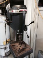
I've got a new to me Craftsman 150 in great cosmetic shape (no arc of shame).

I've searched a bit and cant find a definitive answer on a few things:
What are the bearings required to rebuild this?
Is removing/reseating the chuck gonna help with runout?
Is a tool required to remove the chuck, or could a reasonably well equipped box provide a substitute tool?

Thanks!
 

Attachments

  • IMG_5422.jpg
    IMG_5422.jpg
    90.2 KB · Views: 67
To avoid these ads, REGISTER NOW!

nine4gmc

Well-known member
Joined
Mar 24, 2012
Messages
14,357
Location
Dallas
I think you'll need a chuck wedge to remove the chuck, THEN check run out on the spindle. If the spindle has run out, it is either warped/bent or you need bearings. Check the spindle before you spend money on bearings unless you plan on a complete resto. If you do decide to buy bearings, compare the number stamped on the oem bearing ALONG with the inner dimension. IIRC, the bearings were special size due to inner dimension.

Bearings have different specs as well, ABEC1 is a standard bearing with standard tolerances, ABEC3 is a tighter tolerance(the ones I use) and ABEC5 are high precision and more expensive, harder to find.
 

alan camby

Well-known member
Joined
Dec 3, 2011
Messages
1,566
Location
South of Indianapolis, Indiana
A lot of those old 100/150's have a collar that is threaded onto the spindle shaft.
The collar is right above the chuck.
Put a large Allen wrench in the chuck and loosen the collar. Loosen the collar and it might push the chuck off. If it does not, use the collar to apply preload and lightly tap on the side of the chuck with a brass hammer.

Either way, the chuck will not come off with that collar tight. It is designed so that the chuck can have a little side load during use and not pop off the 33taper while drilling
 
OP
C

chrismenke

Well-known member
Joined
Mar 2, 2014
Messages
1,131
Location
Sam's Clam Disco, CA
A lot of those old 100/150's have a collar that is threaded onto the spindle shaft.
The collar is right above the chuck.
Put a large Allen wrench in the chuck and loosen the collar. Loosen the collar and it might push the chuck off. If it does not, use the collar to apply preload and lightly tap on the side of the chuck with a brass hammer.

Either way, the chuck will not come off with that collar tight. It is designed so that the chuck can have a little side load during use and not pop off the 33taper while drilling


Awesome tip...chuck came right off.

So I get 3 thou runout at the spindle, and 6 thou on the chuck. It is very much a wavy pattern (uh oh...that makes me think bent spindle).
 

zkling

Well-known member
Joined
Jan 23, 2007
Messages
16,939
0.003" TIR on a clean, spindle tip with a rigid measuring setup is pretty bad IMHO. Needs to be <0.001", as the chuck will then exacerbate the problem. What you can do is mount the chuck at different degree offsets to try and find the position that produces the least ammoun of runout by canceling out one another, but the problem is still going to lie in the spindle. Do the bearings feel smooth?

When you measured run out on the chuck, how did you measure that?
 
OP
C

chrismenke

Well-known member
Joined
Mar 2, 2014
Messages
1,131
Location
Sam's Clam Disco, CA
0.003" TIR on a clean, spindle tip with a rigid measuring setup is pretty bad IMHO. Needs to be <0.001", as the chuck will then exacerbate the problem. What you can do is mount the chuck at different degree offsets to try and find the position that produces the least amount of runout by canceling out one another, but the problem is still going to lie in the spindle. Do the bearings feel smooth?

When you measured run out on the chuck, how did you measure that?

So, when I measured it was a dial gauge eyeballed into perpendicular to and center of the rounds held in place with dial gauge holder in a drill vise. The drill vise was not bolted to the table but I think the 10lbs of mass were sufficient as the result was repeatable from different angles.

The bearings themselves are noisy under power but feel and sound okay when spun by hand.
 

A_Pmech

Well-known member
Joined
May 8, 2007
Messages
8,002
Location
IL
It is very much a wavy pattern (uh oh...that makes me think bent spindle).

A bent spindle will have one high spot and one low spot per revolution.

Multiple high and low spots in random locations is usually a sign of bad spindle bearings.

Multiple high and low spots in exact repeating locations is a sign that the spindle taper is out of round.
 
OP
C

chrismenke

Well-known member
Joined
Mar 2, 2014
Messages
1,131
Location
Sam's Clam Disco, CA
Well, it's coming apart when I get back from some vacation.

I'm not heading back downstairs to measure the spindle again, but I fear the worst. Seems like the whole spindle assembly is still available from Sears Parts...but my deal on the drill will have gone from good to bad after buying a $130 assy.
 
To avoid these ads, REGISTER NOW!

hackwelder

Well-known member
Joined
Jul 12, 2014
Messages
224
I accidentally bent the spindle on my own vintage Craftsman drill press several years ago, ordered a new spindle from Sears and much to my surprise it came complete w/ bearings...don't remember the exact price but do recall that it was very reasonable.
 
OP
C

chrismenke

Well-known member
Joined
Mar 2, 2014
Messages
1,131
Location
Sam's Clam Disco, CA
So I pulled the spindle assy. last night and made some interesting discoveries.

When I have the spindle in a vise and check the runout on the spindle shaft or tip I get less than .001. However, on the threaded collar pressed on the spindle shaft I get .003. This tells me the collar retainer is not square to the shaft. This .003 is present on the chuck and multiplies itself on a bit.

Should I pull it and try to replace it square? If so, any hints on removing a blind roll pin? Or should I try something else?
 

zkling

Well-known member
Joined
Jan 23, 2007
Messages
16,939
For some reason I don't think you are measuring what you need to. Do you have the chuck off the spindle? If not you need to remove it, remount the spindle back in the drill press and then take readings on the male taper surface of the spindle. The threaded collar on the chuck only keeps it from falling off the taper. The taper is what accurately locates the chuck.
 
OP
C

chrismenke

Well-known member
Joined
Mar 2, 2014
Messages
1,131
Location
Sam's Clam Disco, CA
For some reason I don't think you are measuring what you need to. Do you have the chuck off the spindle? If not you need to remove it, remount the spindle back in the drill press and then take readings on the male taper surface of the spindle. The threaded collar on the chuck only keeps it from falling off the taper. The taper is what accurately locates the chuck.

I've measured the spindle shaft above the collar (<.001), the collar (>.003), and the taper (<.001) with the chuck off.

I'm wondering it the chuck/taper seat is being impacted by the collar seeming sloppy.
 

zkling

Well-known member
Joined
Jan 23, 2007
Messages
16,939
I've measured the spindle shaft above the collar (<.001), the collar (>.003), and the taper (<.001) with the chuck off.

I'm wondering it the chuck/taper seat is being impacted by the collar seeming sloppy.


No, the collar just holds it on the taper, the taper is what accurately locates the chuck. If you have less than a thousand TIR on the spindle taper, that is fine. Clean the mating taper surfaces real well and then chuck up a short section of ~1/4" dowel pin, indicate on that, see what you get.

External features of the chuck usually aren't held to that high of a concentricity tolerance in relation to the jaws and mount taper, and thus are a poor reference surface.
 
OP
C

chrismenke

Well-known member
Joined
Mar 2, 2014
Messages
1,131
Location
Sam's Clam Disco, CA
Well, long story to a short point...

It is the chuck.

I get negligible runout on the spindle. Negligible runout on the neck of the chuck attached to the spindle, but plenty of runout on the chuck faces south of the chuck neck (the dynamic parts of the chuck). I've ordered a new chuck and will take a stab at rebuilding the existing one.
 

zkling

Well-known member
Joined
Jan 23, 2007
Messages
16,939
Are you still measuring the external features of the chuck? What happens when you put a 1/4" dowel pin or the like in the chuck as if it were a drill bit, then indicate on that?
 
OP
C

chrismenke

Well-known member
Joined
Mar 2, 2014
Messages
1,131
Location
Sam's Clam Disco, CA
Dowel pin is like a floppy arm balloon man at a used car dealership. The slop is in the chuck.

If I start at the dowel pin and move up, I find myself seeing a marked reduction in slop all the way up the pin, up the chuck faces (yes, I know they're not ideal, but the reflect what's going on further down the same plane on the dowel pin), until I get to the uncollared neck of the chuck. The neck, with the collar removed is sitting directly on the morse taper, and reflects the exact same <.001 I see on the taper. This tells me the spindle taper is getting a good joint with the receiver on the neck of the chuck, and that problems are south of that.

I'll eat my words if a new chuck doesn't solve the problem, but I can see the logic of what I'm measuring and how it reflects the problem. Also, when I finally got to eyeballing the chuck closely, I think it may have been rebuilt with the jaws out of order once before...the do not close as nicely as they should.
 
To avoid these ads, REGISTER NOW!
Top Bottom