To avoid these ads, REGISTER NOW!

Craftsman Drill Press

OP
F

FrankLee

Well-known member
Joined
Sep 13, 2010
Messages
3,553
Location
seMI, 48317
Ok you got me with then remove the handle.
Can I interpret that as I can continue to unscrew the quill lock handle right out of the head?

No. There is a 3/32" hex socket set screw that holds the handle onto the lock bolt head. The handle is made of pot metal and removing it will eliminate the risk of breaking it.


Below is a picture (bottom) of a table lock from an early Craftsman 100. Same design as all quill locks only larger.

 
Last edited:
To avoid these ads, REGISTER NOW!

tamperista

Member
Joined
Oct 25, 2016
Messages
10
Location
Ithaca, NY
On the topic of cross uses for salvaged DP tables, here's a mohawk 103.0305 remnant that I use to support a lil' Shopmaster saw. It has a tiny footprint in my crowded shop, and I use it just for quick crosscuts when the other saws are set to dead angles that I don't want to disturb. (Remind me to rob that locking handle to use on a '100' DP)
 

Attachments

  • Shopmaster Saw resized .jpg
    Shopmaster Saw resized .jpg
    75.2 KB · Views: 104

pendragon1998

Well-known member
Joined
Mar 24, 2012
Messages
3,733
Location
NE Georgia
Stellar thread!

I am restoring a 100 and the rods on my motor support assembly (no. 40 in the exploded parts view) seem a bit loose. Are they threaded or just press fit?
 

Attachments

  • 14775406822340.jpg
    14775406822340.jpg
    106.1 KB · Views: 91

nine4gmc

Well-known member
Joined
Mar 24, 2012
Messages
14,357
Location
Dallas
Hey Pendragon, the rods on my 100 motor support have nuts on the motor side of the plate that hold the plate tight. The rods slip fit through holes cast in the head but there are bolts that thread in from the side to lock them in place.
 
OP
F

FrankLee

Well-known member
Joined
Sep 13, 2010
Messages
3,553
Location
seMI, 48317
Motor Mount Repair

Are they threaded or just press fit?

Many motor mount rods are pressed in and can be punched out. The rod ends are turned down to 1/2" and knurled.

Quite often these rods will loosen. The rod in the photo below was loose but still required a punch to knock it out. I had one mm where the rod would just fall out.

These can be repaired with a red thread locker. The mating parts must be very clean for the thread locker to hold tight. If you go this route, be sure to slide the mm into the head frame immediately after inserting the rod into the mm with the thread locker. This will keep the rods aligned correctly. Otherwise the thread locker can cure with the rod slightly mis-aligned. This could make it more difficult the insert the assembly into the head frame later. (Been there, done that.)

 
Last edited:

pendragon1998

Well-known member
Joined
Mar 24, 2012
Messages
3,733
Location
NE Georgia
Thanks for the advice. Hey, now how about that Cratsman King Seeley blue paint...any spray can matches available? I don't know if this table saw is original or matched, but this is the color I like.

attachment.php
 

Attachments

  • 19176-B.jpg
    19176-B.jpg
    50.2 KB · Views: 881
OP
F

FrankLee

Well-known member
Joined
Sep 13, 2010
Messages
3,553
Location
seMI, 48317
Thanks for the advice. Hey, now how about that Cratsman King Seeley blue paint...any spray can matches available? I don't know if this table saw is original or matched, but this is the color I like.

I don't usually try to match oem colors, but there are resources available online regarding Craftsman paint colors:
 
Last edited:

smalltown

Well-known member
Joined
Jul 9, 2015
Messages
985
Location
Western Maine
FrankLee thanks for the pictures. Everything is scheduled for a Sunday road trip. I will be unable to power up the press to test as it now sits in a storage container, however it appears to have been well cared for. So unless something is obviously wrong I will lug it home. Since it's at a storage location I most likely will be trying to disassemble things outside so your suggestion on tools to carry helps a lot.
 
OP
F

FrankLee

Well-known member
Joined
Sep 13, 2010
Messages
3,553
Location
seMI, 48317
FrankLee thanks for the pictures. Everything is scheduled for a Sunday road trip. I will be unable to power up the press to test as it now sits in a storage container, however it appears to have been well cared for. So unless something is obviously wrong I will lug it home. Since it's at a storage location I most likely will be trying to disassemble things outside so your suggestion on tools to carry helps a lot.

You're welcome. A few minutes ago, I made a few minor changes in the linked page above.

Before pictures may help too. Be sure to give us an update on Monday.
 

tamperista

Member
Joined
Oct 25, 2016
Messages
10
Location
Ithaca, NY
Hi everyone. One of the Craftsman 100 drill presses I refurbished had a Jacobs 6A chuck that was bound tightly on the taper, and the plain solid pin that retains the threaded lower collar to the spindle was sheared so that the collar could not be used to press the chuck off with wedges. I drilled a hole in the center of the inside of the chuck body in steps using 3/16", 1/4", and 5/16" bits held vertically in a vise that had a vertical V in the fixed jaw, using the DP to rotate the chuck. I threaded the hole to 3/8-16, and used a 1" long socket-head cap screw threaded into the hole to press the chuck off. It only took a few minutes, and when I was finished disassembling and cleaning the chuck, I put a shorter set screw back into the threaded hole to prevent getting swarf up in there, whenever the chuck gets used again. I didn't invent this method: I think it's been around for a while.
 

Attachments

  • DP chuck removal screw resized.jpg
    DP chuck removal screw resized.jpg
    65.9 KB · Views: 56

taumac

Well-known member
Joined
Aug 30, 2011
Messages
8,104
Location
Brooksville, Fl
Many motor mount rods are pressed in and can be punched out. The rod ends are turned down to 1/2" and knurled.

Quite often these rods will loosen. The rod in the photo below was loose but still required a punch to knock it out. I had one mm where the rod would just fall out.

These can be repaired with a red thread locker. The mating parts must be very clean for the thread locker to hold tight. If you go this route, be sure to slide the mm into the head frame immediately after inserting the rod into the mm with the thread locker. This will keep the rods aligned correctly. Otherwise the thread locker can cure with the rod slightly mis-aligned. This could make it more difficult the insert the assembly into the head frame later. (Been there, done that.)


Wow, thanks for the tip. One of mine is loose and was wondering how to fix it.
 
OP
F

FrankLee

Well-known member
Joined
Sep 13, 2010
Messages
3,553
Location
seMI, 48317
... the rods on my motor support assembly ... seem a bit loose. Are they threaded or just press fit?
Wow, thanks for the tip. One of mine is loose and was wondering how to fix it.

You're welcome. It worked very well on the one I did. So well that I could not punch it out (cold) when I tested the fix. If/when you do this, please post your results.


On the topic of cross uses for salvaged DP tables, here's a mohawk 103.0305 remnant that I use to support a lil' Shopmaster saw. It has a tiny footprint in my crowded shop, and I use it just for quick crosscuts when the other saws are set to dead angles that I don't want to disturb. (Remind me to rob that locking handle to use on a '100' DP)

Hi everyone. One of the Craftsman 100 drill presses I refurbished had a Jacobs 6A chuck that was bound tightly on the taper, and the plain solid pin that retains the threaded lower collar to the spindle was sheared so that the collar could not be used to press the chuck off with wedges. I drilled a hole in the center of the inside of the chuck body in steps using 3/16", 1/4", and 5/16" bits held vertically in a vise that had a vertical V in the fixed jaw, using the DP to rotate the chuck. I threaded the hole to 3/8-16, and used a 1" long socket-head cap screw threaded into the hole to press the chuck off. It only took a few minutes, and when I was finished disassembling and cleaning the chuck, I put a shorter set screw back into the threaded hole to prevent getting swarf up in there, whenever the chuck gets used again. I didn't invent this method: I think it's been around for a while.

Thanks for your contributions! I did half of the chuck removal technique up in post #137 but did not think to thread the hole.
 
Last edited:

smalltown

Well-known member
Joined
Jul 9, 2015
Messages
985
Location
Western Maine
Well no drill press road trip for me. The seller just called, and I was hoping they were calling just to confirm my arrival Sunday, but instead to inform me they sold it.
 

kevrobster

Member
Joined
Sep 24, 2014
Messages
23
You're welcome. It worked very well on the one I did. So well that I could not punch it out (cold) when I tested the fix. If/when you do this, please post your results.


Thanks for your contributions! I did half of the chuck removal technique up in post #137 but did not think to thread the hole.


Sent from my XT1254 using Tapatalk
 

pendragon1998

Well-known member
Joined
Mar 24, 2012
Messages
3,733
Location
NE Georgia
I am replacing the motor bearings in my 115.6962 motor that runs my 100 series DP. The bearings are New Departure 8502, which can be replaced with Accurate 87502, Extended Inner Ring, Felt Seal Type Ball Bearings.

I was wondering if there is a better option over the felt sealed bearings, and where I can go to find other bearings that fit? I previously used Nachi bearings on my grinder, and I've been happy with them. Or should I just stick with the Accurates? They look like they are about $17-20/ea.

attachment.php
 

Attachments

  • 14777943935280.jpg
    14777943935280.jpg
    72 KB · Views: 1,337
Last edited:
OP
F

FrankLee

Well-known member
Joined
Sep 13, 2010
Messages
3,553
Location
seMI, 48317
I am replacing the motor bearings in my 115.6962 motor that runs my 100 series DP. The bearings are New Departure 8502, which can be replaced with Accurate 87502, Extended Inner Ring, Felt Seal Type Ball Bearings.

I was wondering if there is a better option over the felt sealed bearings, and where I can go to find other bearings that fit? I previously used Nachi bearings on my grinder, and I've been happy with them. Or should I just stick with the Accurates? They look like they are about $17-20/ea.

For motors/grinders, I typically replace the originals with sealed bearings with the same dimensions, if available.

Also, I don't believe that Accurate has their own branded products. That Accurate 87502 could be Nachi (Japan), TPI (Taiwan), or some other manufacturer.

 
Last edited:

tamperista

Member
Joined
Oct 25, 2016
Messages
10
Location
Ithaca, NY
Hi all. If you have access to a lathe, here's a refurbishing step you can take that will yield satisfying results. Chuck an arbor (ground shaft, drill rod, straight piece of stock) in an accurate collet and carefully mount your step pulley with the set screw to obtain minimum runout. If necessary and possible, create a second tapped set screw hole at 90 degrees to the original to get very low runout. Carefully tap any pulley flange dings in or out using your favorite tapping tools, and then machine new matching sides on the pulley grooves to match the original angle. You'll probably only need to remove .004"-.007" per side to get smooth faces, and it doesn't take very long after you've done a few.

View media item 64854
 

tamperista

Member
Joined
Oct 25, 2016
Messages
10
Location
Ithaca, NY
Hi all. During refurbishment, I've found a couple of threaded locking collars at the bottom of the spindle on Craftsman drill presses that had a sheared retaining pin through the spindle. I've also found variations in the holes through the collars for the pin, including a 3/16" hole through one side of the collar and a 3/16" blind hole halfway through the other side, and a 3/16" hole halfway through the second side with a 1/8" hole the rest of the way through to provide access for a punch.
My procedure is to remove the original plain pin, align the collar and spindle holes carefully in the original (or best) orientation, and drill the 3/16" hole out through the second side of the collar. I then install a roll pin ground in length to fit just below flush with the outsides of the collar to retain the collar.
Since the collar is originally a fairly rough-turned part that likely rotates with visible wobble, I chuck the 5/8" spindle w/collar in an accurate collet on the lathe and take the lightest cut on the top and bottom faces and on the OD, so the collar spins true and perpendicular with the spindle. I'm not really trying to polish it into jewelry, I just prefer to see the spindle/collar/chuck assembly spin true when the machine is in use. Here is a photo to show the results:

chuck and spindle.jpg
 
Last edited:
OP
F

FrankLee

Well-known member
Joined
Sep 13, 2010
Messages
3,553
Location
seMI, 48317
Refurb DP#25

10/31/2016

I sold dp#23 today... it was one of the last Craftsman 100's made. I believe it was manufactured in early 1958, just before the 150's came out.

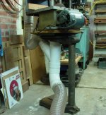
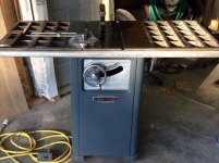
The buyer has another Craftsman 100 drill press and wanted it reconditioned, so I took that one home with me to work on. This one, dp#25, is a 103.23130 and was a very early 100. The motor is stamped E4-47, so made in 1947.

I didn't get any good before pictures, but these were from when I got it home in pieces.


11/2/2016

I got dp#25 apart and ordered new belts from www.VBeltSupply.com and bearings from www.AccurateBearing.com.


I found a couple issues that I've never seen before.

First, I could not for the life of me get the tilt table off of the table support. I was eventually able to tilt the table, but it took considerable effort. I'm still not sure what the problem is, but it may have something to do with the tapered pin. It was jammed into the support much farther than I've ever seen.


The second issue is with the feed stop rod bracket.

In an earlier post, I showed that there were two designs for this bracket. The slot in the earlier design, on the left, did not extend through. The later bracket is on the right.


The bracket on dp#25 is the earlier design. It was only partially seated onto the quill and very difficult to remove. It would not fully re-seat onto the quill. I surmised that because of the closed-loop design, tightening the bracket bolt deformed the bracket. The ID was reduced to the point where it was very tight on the quill. I tried to hammer a wedge into the slot, but still no go.


To correct the problem, I extended that slot with a hacksaw blade to mimic the later design. It works perfect now!


11/5/2016

All parts are cleaned and polished. Today, I installed the new bearings and reassembled the head frame.


Back together for a test run. Nice!

 
Last edited:

nine4gmc

Well-known member
Joined
Mar 24, 2012
Messages
14,357
Location
Dallas
Sweet Frank, how many do you keep around for personal use? I honestly don't think there are 23 in the entire state of Louisiana, only seen two other than mine in the wild.
 
To avoid these ads, REGISTER NOW!

tamperista

Member
Joined
Oct 25, 2016
Messages
10
Location
Ithaca, NY
Adding snap ring groove to DP quill

GALLERY]


I like the idea of "updating" the stop rod bracket to the more friendly design. Along that vein, I also add an update to any quill I happen to have out of a Craftsman DP in the area of the stop bracket.
The original snap ring groove that's present on some quills serves an important purpose, as Frank Lee has pointed out. It's located just above the top of the stop rod bracket, which will be about 3/4" up from the bottom of the quill when the bracket is seated (some have a "seat" or ledge in the bottom of the bracket: some don't). If I have the quill out of a DP and it has no snap ring groove, I take a few minutes to chuck it in the lathe and add a groove. This updates the quill, similar to updating the stop rod bracket by extending the saw cut, as Frank has shown. I center the groove at 13/16" from the bottom of the quill, and cut it .068" wide by .098" deep, similar to the measurements I took from a 150 quill. The quill can then be reassembled with a snap ring and an O-ring or rubber gasket to absorb the shock when the quill returns to the raised position, and your early and late model quills will not be jealous of one another.
You can see that the quill in the photo had been returning to the top of the stroke without a snap ring to arrest it, and the stop rod bracket had been pushed down partially off the bottom of the quill, allowing the quill to retract too high up into the casting. The top quill collar was banging on the bottom of the spindle pulley bearing, and the locating screws were bent, as described by Frank Lee in an earlier post. All fixed now! :beer:
 
Last edited:

smalltown

Well-known member
Joined
Jul 9, 2015
Messages
985
Location
Western Maine
I noticed a Craftsman 150 for sale it's the bench model, and I had been hoping to find a floor model. I imagine the only difference between the bench and floor models is the length of the column?
Something tells me finding just a column for a 150 floor model would be difficult, but does anybody know what the column diameter I would look for?
 
OP
F

FrankLee

Well-known member
Joined
Sep 13, 2010
Messages
3,553
Location
seMI, 48317
I noticed a Craftsman 150 for sale it's the bench model, and I had been hoping to find a floor model. I imagine the only difference between the bench and floor models is the length of the column?
Something tells me finding just a column for a 150 floor model would be difficult, but does anybody know what the column diameter I would look for?

The base on a floor stander is much larger than a bench model.

The diameter on all Craftsman 100's , 150's and even many other manufacturers' drill presses is 2-3/4". Bench and floor columns and bases are interchangeable

There is a top and bottom to Craftsman bench and floor DP columns. At the top, there is a machined inside diameter approximately 2"deep designed to accommodate a Multi-Speed Attachment.

Craftsman floor standing columns were reduced from ~67" to ~62" in the 1956 model year.

I have two spare floor columns and bases if you can figure out how to ship it.


Is this the one to which you are referring? http://nh.craigslist.org/for/5868312021.html It is an early 150 with the external spring tension knob.

IMO, it looks like an OK deal with the vise... assuming everything is OK; motor, runout, etc. It needs some clean-up, has some holes in the table, and the motor pulley is much larger than I prefer.
 
Last edited:

smalltown

Well-known member
Joined
Jul 9, 2015
Messages
985
Location
Western Maine
Good grief Frank you surprised me with that information. I haven't contacted the seller so I do no know if the vise comes with it. Is an early 150 with an external spring tension a good are bad thing? I can't imagine how you could tell that the motor pulley size was?

I guess having restored as many as you have things must jump out at you.

Ya Michigan would be a hike for me, and I think the columns are quite heavy to ship?
 

Cruzan80

Well-known member
Joined
Jul 22, 2015
Messages
4,176
Location
Denver, CO
To give you an idea, both mine and my buddy's were that price for floor models. We are not in the cheapest part of the country (Denver, CO), but watching and waiting helped.

IMO, an early 150 with external spring isnt a good/bad thing, as much as it is just informative. Later 150's went to a traditional coil spring (think porch swing) rather than a curved piece of metal spring like the earlier designs. I think he is referring to the motor pulley not looking like it is a stepped pulley, but a single groove, limiting the amount of speed differences.
 

smalltown

Well-known member
Joined
Jul 9, 2015
Messages
985
Location
Western Maine
Cruzan yes I see that now that you pointed that out. That's what I have been doing watching and waiting. I had one about two weeks ago that I was intending on buying made the arrangements to meet the seller out of state when suddenly the seller sold the drill press. At least they called before I left the following day.
 
OP
F

FrankLee

Well-known member
Joined
Sep 13, 2010
Messages
3,553
Location
seMI, 48317
Good grief Frank you surprised me with that information. I haven't contacted the seller so I do no know if the vise comes with it. Is an early 150 with an external spring tension a good are bad thing? I can't imagine how you could tell that the motor pulley size was?

I guess having restored as many as you have things must jump out at you.

Ya Michigan would be a hike for me, and I think the columns are quite heavy to ship?

The external spring tension knob is my preference. I like that the pinion shaft is "locked" into the head frame with a dog-point screw on the early DP's. The later style with the integrated spring attachment works well too.

All King-Seeley and Emerson 100's and 150's use a torsion spring. The later 150's torsion spring also serves as an extension spring and is the only mechanism holding the pinion shaft into the head frame.

A single-step motor pulley works just fine, but that pulley looks to be about 3-4". It also looks to be linked to the second step on the spindle pulley which is approximately the same size as the motor pulley. That combination is PDQ. Assuming a 1750 rpm motor, the spindle/chuck is likely spinning near 1750 rpm's. IMO, that is fast!
 
Last edited:

RHJO51

Well-known member
Joined
Feb 27, 2015
Messages
242
Location
Red Hook, NY 12571
Hello Frank, I stumbled on a nice little Craftsman drill press, a 103.23100 just like the one you wrote about. It's small, but all there and in good shape. I'm taking it apart and had a question for you. I'm trying to remove the spindle pulley with no luck so far. I removed the two set screws but can't pull the pulley off the splined sleeve. I've got it soaking with penetrating oil. I see that if I grasp the pulley it moves easily up and down a good 1/2 inch - is this normal? Inside the head there looks like a snap ring on the bottom of the splined sleeve, I'm guessing that needs to come off in order to pull out the splined sleeve. Any thoughts? Thanks - Jim
 
OP
F

FrankLee

Well-known member
Joined
Sep 13, 2010
Messages
3,553
Location
seMI, 48317
Hello Frank, I stumbled on a nice little Craftsman drill press, a 103.23100 just like the one you wrote about. It's small, but all there and in good shape. I'm taking it apart and had a question for you. I'm trying to remove the spindle pulley with no luck so far. I removed the two set screws but can't pull the pulley off the splined sleeve. I've got it soaking with penetrating oil. I see that if I grasp the pulley it moves easily up and down a good 1/2 inch - is this normal? Inside the head there looks like a snap ring on the bottom of the splined sleeve, I'm guessing that needs to come off in order to pull out the splined sleeve. Any thoughts? Thanks - Jim

I don't recall having any problem sliding the pulley off the splined sleeve. The two set screws tighten against two flats on the sleeve. It almost sounds like the set screws are not backed out enough, but you said they were removed, correct?

What I think may have happened is that the screws were tightened on the curve of the sleeve or edge of the flat and there is a burr catching somewhere.

A few things to try...

First, with the spindle installed, grab the chuck and try to twist the pulley off the sleeve.

Second, if possible, remove that snap ring and pull the pulley and sleeve out from the top. Then, through the set screw hole, you can spot the witness marks from where the set screws were tightened.

Third, with the spindle removed, GENTLY tap the sleeve down through the pulley with a dowel or similar.
 
Last edited:

Dave_NY

New member
Joined
Sep 6, 2016
Messages
4
Hi all,

First post to garage journal but I've been lurking here and there. I recently picked up a nice Craftsman 113.213780 drill press and it came with the old style chain lift for moving the table up and down.

I really don't need this and before I threw it out I figured I would ask if anyone here on the board could use it, all I would ask is a few dollars to cover shipping.

Attached are some photos, you can see the handle piece is broken where it would attach to the table:

KpYGqDnyEE_JHYNPSef5wnSdcLoH_i_JHt4ccoK4wcJjr-f0AGiWG70S6FXHYVfjq6nuLAQmmoEWn_3_REh4CtfztcW6iTmbCzxJAHu_cinamiUhow0QulHhC57v5LAd1fbkHipjynA0GAovqENBPhACB2VvQC7a8LuPJFZTzpHNcbNMv9snLnbACs7FHDgbTH8kMJ86egNmGskvTaUMU3iqxPQc0AXlovkPooHVszDXDTEUGt8hGMicQ0-zBTYpHyEnKIGH7AJD4Jr6JD55ja1eYdODXcZCasZcnAwgs3qGIT1uv1zFoU0h2BE5oTj0QPrmRl4ewdJ0Jy9364j1Uae6audN4OZhH2lUzKcu4ztwOkwnWUUumXyuNdrrBJTa7MdPdHb9hmnlhspmMMsAeBT5NI3ulpkiGeT5ODrchSvA3GFtjTY76Gc-TJw1fOi8DxAMij27XjXHLDS_djyqxRnZJPHuq2YyKIyylIAczLdtPzsrKSKEoizcmZ06Sl-MLH9ezcN3WlkRsnZ3j6tLCG4Bcf_Wd_aImzmhlAjIRiAtLbt8leQIxF8xOw37LcDAOR3pjORY3nIP3aTaAP6pP4E_w-SkdDfLvfqUDtzIPj2JfE5G=w439-h780-no


C3Ha7nbR7C17ZiRnxz7_ZfXQccUX_ZTZNE-MfA75pCba2HXiPJqWsuvcLYJNdH5IF6J6vdcm2YCsDN6f6dR976ibmAL64L0FesjxQoxKiej8OnZCG7XlEO9x8Lq2O3D5YejBydFOQp8U9Bpmq7wxeLJsvprc8iVqGMoqwAVoIV9Gbt_A9svehkTTgnH45eKzSieK3fvILwLBJIIwZCUXaIUIll1sTgziYFnF7A17sLoGf4qlvc7p48yIkiXQ4ECVEbZhVcc19xnZMqfxeoc-Uti43-YBg9HWFzeL3dXzFYQVsmdsKmmLTf3jOMcGfG4rrPZnh62GGmNbFy7V2PoAOLZk6RzO81I6OlJg2P3AWDLQFKNtf1FOhUeJDb4jRuPUt9kex8ed8yzETYMuGDTikpxPjseb277YuMh93kaH5pZ7FJp2JXrbCfuuGgRDSsQRJ8SNoXI93Rcrhm1DaN7BNJ-yOz7bbnUbmveRDxsSHG7ZTt27qGicg1JHoQS9vINijdSaegouXsj_O8iobNridvDtzkhIdnzyhcmzghfntyusHRrCb5DsKd27OGuw1Lwrwo_M5gbXTNPNxsAqVqIvutEVu3g8qkzLpD3L83rRLArX28cN=w439-h780-no


emMkNStka_ziBFdiPtPG7Sl1NZ5J6bqmkLeWLA2WdUIYSHNzM80ruqFTrLazFHETRAfdXurdguK2MvXsj_C030gZjMbf7kkfwuYhJJyNeC7GxOle_EWz8_2mNhk-YG5gcgZ5UuHk7UlJLxcLOpnyRiDr9NcxwzoU5JfOh8TQMo7Uiuh8GGto5kTyJy-vzkNQUMCLF9eFTtaj_4osr2mE5UcxDZbKVBOzJxhLLKFTdwHSXRnpUnb4hBG-6EzUGIziLIupu8ior7PjIPcFllqZ8Hp_IbxVmmuW5LGazvxmAf2TDDSweDILo980JTXhQPCEGVqf7SqoDaFcXesolbR3b5Mbd26o7bJ9mFBTt8TTaVcFH0Ss1tXqQuDok6l1ersYldpYnkNf78SanTDMz1FFchy8wvNwibNrmWkadOrbX7FJTxYsCRDvihKG0qQ4UVQE5Tu3HfKBSTdcH5S-3WgTKhJ-gki2MSBGjEiBSZbKDS-TBfrVrQclfq6RltgrDk2KeiZhekO2A82RuXWGWWdy34DCoNGMyc_xoUN0B3gIaJY7bfcwMATGZqi8fOl9K5346U7gRPQDFF1vf-6mnUur1yjAlZeJ6qY9gjaKJ17Wi6ECAMUR=w1387-h780-no


It is the same lift as shown on these other GJ forum pictures:

IMG_3892_zpsyjeybbqs.jpg


IMG_3893_zpsdd6hjoo4.jpg


Anyways I hope someone can put this to good use I just don't need it kicking around my garage!
 

Dave_NY

New member
Joined
Sep 6, 2016
Messages
4
And while I'm here maybe some of you all can give some info on the DP I bought. It's a 113.213780 in really good condition. I bought it from a guy who had it sitting in a garage for 7 years or so, he bought it off of the original owner who used it in a wood shop. It still has the original belt plus two extra belts stashed away in the housing that covers the pulleys.

Fires right up, there is a bit of noise coming from the front pulley but I haven't had a chance to pull the pulley and inspect/lube. Runout is within reason, .001 on the spindle and .003 on the chuck.

I'm going to be using it primarily for drilling various fasteners for safety wiring (bought a decent cross slide vice and bolted it to the table), can this drill be used for light milling at all? The chuck is a Jacob's 633C 33 and from what I can gather that chuck was used on Craftsman presses and intended for milling. I'm not talking about anything serious, maybe some aluminum to fab up some motorcycle parts.

Any information or advice is appreciated!
 

Cruzan80

Well-known member
Joined
Jul 22, 2015
Messages
4,176
Location
Denver, CO
Re: The Classic Craftsman 100/150 Drill Press

I wouldn't subject it too much axial load. Bearings tend to t trashed pretty quick that way. Checked the set screws on the front pulley yet?

Sent from my VIVO IV using Tapatalk
 
OP
F

FrankLee

Well-known member
Joined
Sep 13, 2010
Messages
3,553
Location
seMI, 48317
Hi all,

First post to garage journal but I've been lurking here and there. I recently picked up a nice Craftsman 113.213780 drill press and it came with the old style chain lift for moving the table up and down.

I really don't need this and before I threw it out I figured I would ask if anyone here on the board could use it, all I would ask is a few dollars to cover shipping.

Attached are some photos, you can see the handle piece is broken where it would attach to the table:

It is the same lift as shown on these other GJ forum pictures:

Anyways I hope someone can put this to good use I just don't need it kicking around my garage!

And while I'm here maybe some of you all can give some info on the DP I bought. It's a 113.213780 in really good condition. I bought it from a guy who had it sitting in a garage for 7 years or so, he bought it off of the original owner who used it in a wood shop. It still has the original belt plus two extra belts stashed away in the housing that covers the pulleys.

Fires right up, there is a bit of noise coming from the front pulley but I haven't had a chance to pull the pulley and inspect/lube. Runout is within reason, .001 on the spindle and .003 on the chuck.

I'm going to be using it primarily for drilling various fasteners for safety wiring (bought a decent cross slide vice and bolted it to the table), can this drill be used for light milling at all? The chuck is a Jacob's 633C 33 and from what I can gather that chuck was used on Craftsman presses and intended for milling. I'm not talking about anything serious, maybe some aluminum to fab up some motorcycle parts.

Any information or advice is appreciated!

I wouldn't subject it too much axial load. Bearings tend to t trashed pretty quick that way. Checked the set screws on the front pulley yet?

Sent from my VIVO IV using Tapatalk

Hello Dave and welcome!

Don't throw that lift away! A whole one just sold on ebay for $255.00. Parts should be worth something. Do you have the broken-off piece?
http://www.ebay.com/itm/VINTAGE-CRA...tmdES4FJCBevDYi7IrR4s%3D&orig_cvip=true&rt=nc

I have no experience with that model to fully answer your questions, so Cruzan80 and hopefully others will chime in. There are drill press accessories to perform planing, routing, shaping, and drum sanding wood. Those are all axial operations. So I think light milling on aluminum would be ok.

The owner's manual from 1983 is still available on SPD:
http://www.searspartsdirect.com/par...man-parts-craftsman+15-1-manual?manualIndex=0
 
Last edited:

Dave_NY

New member
Joined
Sep 6, 2016
Messages
4
Hello Dave and welcome!

Don't throw that lift away! A whole one just sold on ebay for $255.00. Parts should be worth something. Do you have the broken-off piece?
http://www.ebay.com/itm/VINTAGE-CRA...tmdES4FJCBevDYi7IrR4s%3D&orig_cvip=true&rt=nc

I have no experience with that model to fully answer your questions, so Cruzan80 and hopefully others will chime in. There are drill press accessories to perform planing, routing, shaping, and drum sanding wood. those are all axial operations. So I think light milling on aluminum would be ok.

Here is an owner's manual for a very similar model:
http://vintagemachinery.org/pubs/222/5471.pdf

Actually, the owner's manual from 1983 is still available on SPD:
http://www.searspartsdirect.com/par...man-parts-craftsman+15-1-manual?manualIndex=0

Alas I do not have the part that broke off. When I bought the press the guy kind of handed the chain to me as an afterthought, I knew what is was but I don't think he had any idea. That's a crazy amount of money for this thing! I would still rather give it to someone on the forum who will put it to good use because it will just sit around in my shop collecting (even more) dust.

I found a scanned copy of the manual online which is great but it doesn't get into any details about milling. It does mention using a drum sander which is similar but not as tough on the machinery.

It looks like all of the drill presses from this period were similar, regardless I am happy with the purchase and hope to keep using this thing for a while.
 

Cruzan80

Well-known member
Joined
Jul 22, 2015
Messages
4,176
Location
Denver, CO
There was not a ton of changeover between the 150's and the later ones, besides (obviously more plastic and) the integration of a light inside the head, and moving the power switches to the front. One could argue that they are more beneficial, due to the higher and lower belt speeds possible with a greater stepped pulley on each side.

The power switch on this is the same generic one used in most of the Craftsman tools of this era, so shouldn't have any issues with getting another one if it stops working. The feed stop nut looks a bit gimmicky, and less likely to maintain a good stop. I also don't like how the thumb-screw tightens onto the threads, as it increases the risk of damaging them.

Going to go out on a limb and say that for the one linked in the manual, the feed hub/handles and the head and quill lock look identical to the later Craftsman 150's. The chuck threaded onto the end is also the same. If you need to remove it, the collar will force the chuck off, simply by unscrewing the collar.

Any other questions, please ask. I don't have that specific machine, but have done enough work on CM machines from this era and earlier that I have generic knowledge of how most of the machines work, rather than Frank's specific deep knowledge of the 100/150's.
 

vertguy

Well-known member
Joined
Apr 6, 2010
Messages
1,260
Location
SE WI
I have that same lift and could use a photo of the other side that shows how the sprocket and chain are set up.
 

tamperista

Member
Joined
Oct 25, 2016
Messages
10
Location
Ithaca, NY
Hi Dave, and welcome. I think I'd be more worried about the radial load you'd be placing on the lower spindle bearing than the axial load. Drilling is an axial load. Keep in mind that the milling cutter will try to deflect away from the workpiece, and the sideways push places radial load on bearings that are not designed for radial loading, as well as vibrates your quill back and forth (sideways) to the extent of any clearance between the quill and the head casting as each tooth on your milling cutter engages and clears the workpiece. If the radial load is strong enough, and if there is any appreciable backlash in your workholding method, then it could all add up to the milling cutter "walking" along the workpiece instead of cutting, and you'll be at risk of the cutting tool trying to throw the work and whatever is holding it off of the table. You could get hurt, and you would most likely bend your spindle in the bargain. Any feed screw backlash in a worn X-Y table will add to the risk. Be very careful.
 

Dave_NY

New member
Joined
Sep 6, 2016
Messages
4
Hi Dave, and welcome. I think I'd be more worried about the radial load you'd be placing on the lower spindle bearing than the axial load. Drilling is an axial load. Keep in mind that the milling cutter will try to deflect away from the workpiece, and the sideways push places radial load on bearings that are not designed for radial loading, as well as vibrates your quill back and forth (sideways) to the extent of any clearance between the quill and the head casting as each tooth on your milling cutter engages and clears the workpiece. If the radial load is strong enough, and if there is any appreciable backlash in your workholding method, then it could all add up to the milling cutter "walking" along the workpiece instead of cutting, and you'll be at risk of the cutting tool trying to throw the work and whatever is holding it off of the table. You could get hurt, and you would most likely bend your spindle in the bargain. Any feed screw backlash in a worn X-Y table will add to the risk. Be very careful.

Thanks for the response, you are correct I should have said radial load. I was more curious than anything, if I do use the DP to mill it will be small aluminum brackets and other small things. If I really want to get into milling I will most likely buy a separate machine for that.
 
To avoid these ads, REGISTER NOW!
Top Bottom