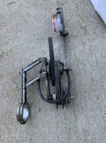
DP#66 with Table Lift
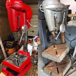
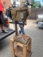
dp#66 is a late Craftsman 100, model 103.24520. Originally a bench model, a previous owner installed a solid steel column.


9/23/2019
I got dp#66 apart today. Three things made this a very difficult undertaking.
- I wanted to remove the main screw on the table lift first. There are a pair of jam nuts at the top of the main screw. The first came off OK, but the second just rotated without any vertical movement. Either the nut was stripped, the main screw threads were stripped, or both.
Using a couple nut splitters, and because of the thinness of the jam nut, it took about two hours and lots of cursing to get that nut safely removed and the main screw off. More on the jam nuts below.
- The diameter of the solid steel column was a problem.
Out of all the manufacturers I'm familiar with, I believe King-Seeley/Emerson drill presses have the smallest of the so-called "2-3/4 inch" diameter columns. The head frame and the base castings were both very tight.
I got the base off first using the 2x4-with-a-BFH method. I tried that method on the head frame casting with very little progress. I then tried a couple puller set-ups which worked well for as far as they could reach; about 6". The 2x4-with-a-BFH worked well after that.
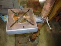
The table lift collars and the table seemed to move OK on the column which makes me think the table bore may have been honed to work better. Atlas made the table lift which I think has a slightly larger bore.
- Due to the sheer weight of the solid column, it was difficult to maneuver and hold the assembly in the best positions to remove the parts.
Jam Nuts & Main Screw
Below are pictures of the jam nuts and the end of main screw after removal. It turned out that both pieces were stripped. Fortunately, at least four of the eight or so threads are still good.


You can see that I attempted to split that nut on each side. The splitter kept sliding up and off the nut. The corners on both ends of the chisel on my cheap splitter actually broke. Another splitter finally worked, but it wasn't really appropriate with such a thin nut.

These jam nuts normally carry the weight of the drill press table. The bottom surface of this nut is badly worn from wearing against the cast iron gear housing.
This is why I strongly recommend moving the thrust bearing from inside of the housing to the outside (* when used only as a table lift).

The 3/8-16 threaded portion of the main screw is ~17/32" long and the 1/2" portion is 15/16" long. I suppose the proper fix is to cut off both portions to the 3/4" main screw section. Next, on a lathe, drill and tap the 3/4" section for a 3/8-16" stud by ~2-1/2" long. Then, use a 1/2" od x 15/16" long sleeve bearing over the stud.
Because there are enough good threads, I'm going to use a simpler approach... a jam set screw and a threaded coupler. I'll cut down the coupler and use a shorter set screw. It'll look odd, but it'll work just fine. That Nice 603 1/4 thrust bearing was nasty covered with old grease, but there was never any load on it inside the gear housing. It cleaned up like new.


9/27/2019
All the lift parts are cleaned and look great. There are quite a few paint chips, but I like original paint and will be swapping this one onto my keeper machine.
The bevel gears and main screw threads are in great shape. Note that the pin for the crank handle is tapered. It can only be removed and reinstalled from the same direction.
9/30/2019
The cast iron parts cleaned up nicely!
The paint on the base cleaned up good too, but this is another factory re-paint. The original paint was the darker charcoal gray. I always thought that the charcoal gray was only on Emerson machines. Apparently King-Seeley started using it.


10/1/2019
The table lift is back together and works beautifully!


10/09/2019
dp#66 and dp#68 cast iron is cleaned. Most internal parts are cleaned. Motors are cleaned with new cords.
10/10/2019
dp#66 is complete.


![IMG_7859[1].jpg](/forum/data/attachments/821/821807-7e9230883f7cafa49e785c99f869310b.jpg)


")