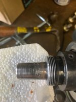
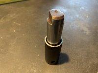
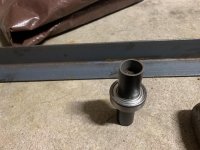
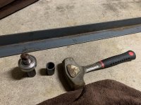
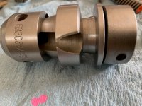
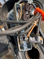
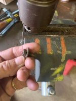
Good news for me! I got the chuck off of the spindle without screwing anything up. Remarkable. I tried a variety of different "tools" to insert into the holes on the chuck collar, punches, homemade grinded steel rod, all without success. I then pulled out my secret weapon, see the pic. A short screw that fit tight, along with a Phillips screwdriver pressing into the collar to help keep the screw in place, and that I could direct a hammer blow to very close to the collar, and viola it came loose. Frank's method of an allen wrench in the chuck and then tightened into a vise was the ticket. There is some amount of galling on the spindle surface. It doesn't look too serious to me. Opinions wanted. Should I clean it, smooth it out with some sand paper and if I do that is there a chance I could change the dimension or balance of the taper part of the spindle. I don't want to put the chuck on something "I have fixed"only to find out it doesn't sit plumb after the "fix". Or should I leave it as is right now? Ok, next is the spindle disassembly to replace the bearings. More later. thanks for reading.
Attachments


Last edited: