While comparing gears for sizing purposes, I ran across an anomaly. Of the five lifts I have found, four had a shaft gear exactly like this one.

Rather than show all of them, they all look like the one above. They have a "lip" at the bottom of the gear bushing. That lip, in conjunction with the overhanging tooth end, sandwich a thin layer of metal around the outer wall so that it can ride inside the gearbox bore without wearing.
In this picture you can visualize how the outer metal shield protects the pot metal from wear as it rides inside a fairly long cast iron bore.

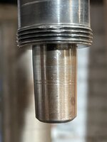
During my comparison I pulled the shaft gear out of a spare lift I have and noted it is one solid piece of metal that was machined.

Here you see that pot metal lip with stress marks all over it next to the solid machined piece.

And flipping it over you can see the machine marks on this solid piece.

Since this was on my spare, I immediately swapped it out with the one on my drill press. It's anyone's guess how something like this could have happened. Maybe it was from a first year run and the bean counters decided it was too expensive to machine, or maybe after complaints of the gears breaking they came up with this as an improvement? We'll probably never know.


")
 . Other than that I have no issues