To avoid these ads, REGISTER NOW!

Above 1200 Sq/FT Craig's Colorado Car Condo

Wokspaces above 1200 squarefeet.
OP
C

Craig Balzer

Well-known member
Joined
Sep 21, 2005
Messages
867
Location
Colorado Springs
MAJOR MILESTONE ACHIEVED.

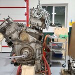
I pulled the engine with only a few steps backwards.
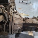
Anyone have a tip (or tips) on separating the ****** from the engine block? -- Note, its all aluminum: block bell housing, everything

  • I removed all bolts noting the long ones and the short ones.
  • A quick thwack or two with a large rubber mallet got the initial separation.
  • The alignment dowels are clear.
  • I have about 1/2" to 3/4" of separation
. . . but no further. I actually have more separation between the block and bell housing than the photo shows -- but not much

Help
 

Attachments

  • 20210526_162924.jpg
    20210526_162924.jpg
    3.3 MB · Views: 116
  • 20210526_154737.jpg
    20210526_154737.jpg
    2.2 MB · Views: 113
To avoid these ads, REGISTER NOW!

Ronin22

Well-known member
Joined
Oct 2, 2018
Messages
478
Location
BA
Somehow I missed this thread.
Awesome work! Love the layout and the cars!
I'll be following along, if you don't mind!
 

shortykorte

Well-known member
Joined
Sep 1, 2014
Messages
8,039
Location
Tallahassee, Fl
Fill bell housing with starting fluid and light?

I wonder if removing the ****** from bell housing would make a difference?


Sent from my iPhone using Garage Journal
 

DennisK

Well-known member
Joined
May 2, 2009
Messages
145
Try some wedges around bell housing, work it evenly. If the input shaft is bad, patience! Belzona can build used to build it back up.
 
OP
C

Craig Balzer

Well-known member
Joined
Sep 21, 2005
Messages
867
Location
Colorado Springs
Guys -- thanx for all your thought.
It turns out I needed to remove the bell housing inspection cover.
Once I did I was able to spin the transmission 360 around the shaft.
That told me there was nothing interfering with removal aside from my reluctance to pull, tug, jiggle a little bit harder

Although, Shorty, I was getting awfully close to lighter fluid and matches
 

Attachments

  • IMG_1639.JPG
    IMG_1639.JPG
    2.2 MB · Views: 94

kberjian

Well-known member
Joined
Jun 1, 2016
Messages
258
Location
Calgary
Seeing the metal casters on the epoxy floor gives me anxiety. How has the floor coating held up?
 
OP
C

Craig Balzer

Well-known member
Joined
Sep 21, 2005
Messages
867
Location
Colorado Springs
I haven't posted in several weeks. On/About 26MAY21, I was hit (and hit hard) with COVID, It took all my strength to separate the engine/****** as above.

Kberjian - the only damage to my epoxy was when moving the engine. I mounted it on the engine stand and kept the cherry picker attached for security when moving the engine. All the wheels on the engine stand moved freely -- until the weight of the engine was on it. I was so fatigued I just kept moving when the third wheel on the engine stand locked up and dragged across the floor; I just kept at it. I haven't investigated the floor closely to see how deep the scratches are.

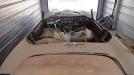
I felt I had recovered sufficiently from COVID to try a few hours in the garage taking more parts of my E-Type on 18JUN21. I set the goal of removing both pieces of the dash cover. It wasn’t difficult getting them off – the hard part was finding the half dozen or so 5/16" nuts -- they were covered/hidden by 50 year old vinyl. I do expect the major challenge to be reattaching the demister hoses.


095b8eee42f4ee06e8985d7dadef628eacad95a6_2_500x500.jpg
Open Dash - Overview I3024×3024 1.89 MB


5cb85992f97b8a39cb71574cd1d3bf42b406e783_2_500x500.jpg
Gauges - Upper Right3024×3024 2.43 MB


90b676e03ab44b375f46eb97ecd67da5b227193c_2_500x500.jpg
Guages - Upper Left3024×3024 2.54 MB
 
Last edited:
OP
C

Craig Balzer

Well-known member
Joined
Sep 21, 2005
Messages
867
Location
Colorado Springs
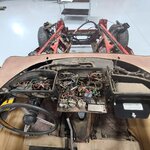
My big problem -- that needed to be resolved before removing any more harnesses -- is that I couldn't see where one harness segment went.

(See first photo) --
In the top center of the photo is what appears to be 2 harnesses in the rectangular opening in the center of the dash – it is actually all one harness. The right side splits and enters the fuse box area beside each tower of fuse boxes. The other splits twice also: one dips downward and to the left toward the steering column (I think) and the other runs under the structure – but I have no idea to where.
The solution is easy: spend $2,000 for EVERY wiring harness in the car and then lay them out on the floor to get a guide as to direction and connection(s). That box ought to arrive this weekend (26/27JUN21) - then the fun begins anew . . .

The harnesses arrived on Friday afternoon and I spent Saturday checking out the 1000+ cars at the Rocky Mountain Hot Rod Nationals in Pueblo. So Sunday I inventoried the box of harnesses and confirmed all items were shipped.

I then unfurled and laid out the two busiest harnesses: the Bulkhead Harness and the Dash Harness. That's when the light bulb(s) came on (pun intended).

I now understand where that mystery harness segment goes. The mystery harness run turns out to snake under the dashboard and speedo/tach and pass through the firewall to the left of the pedals and into the left side of engine compartment. Yay me!

The harness segment in the photo that caused all my consternation is in the upper left corner – tape-wrapped – the attached grommet was the give-away. I was hoping the new harnesses would have clues/tips and I was correct. I also didn’t realize the harnesses were plugged together (the white plugs were that major clear – just gotta figure out where those plug-ins are on the car.

Now on to an increased pace in removing the wiring harnesses since I understand better where they go . . .

Shorty said "so that’s why British electrical is highly sought"
May be now it doesn't look so bad -- -- but maybe not
 

Attachments

  • Open Dash - Overview I.jpg
    Open Dash - Overview I.jpg
    481 KB · Views: 59
  • 20210627_150133.jpg
    20210627_150133.jpg
    1,018.4 KB · Views: 55
Last edited:
OP
C

Craig Balzer

Well-known member
Joined
Sep 21, 2005
Messages
867
Location
Colorado Springs
For some, this would be a minor step in the total clearing of all wiring harnesses in the car.
For me, I stared at the harnesses for 3 days.

And then ordered all the harnesses so I could see how they inter-connected.

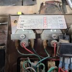
Today (01JUL21) I took a major step forward in removing the harnesses: I found where those block plugs (not the correct term I am sure but it works for me) resided. They were all clustered down low and centered behind the gauge panel. Once I was able to disconnect them, the gauge panel give way with out complaint


Oh -- and I ordered a packet of single wire bullet connecter sleeves. There are 20 in the packet -- -- I'm gonna need at least one more packet of 20 (I'll likely ordered 2 just to be safe). The 2 side harnesses have 9 or 10 wires requiring a handful of bullet connectors:
 

Attachments

  • Successful Extraction of Gauge Panel.jpg
    Successful Extraction of Gauge Panel.jpg
    660.3 KB · Views: 38
  • Gauge Panel with original wiring harness in place.jpg
    Gauge Panel with original wiring harness in place.jpg
    662.9 KB · Views: 33
  • New Panel Harness laid-out showing the Block Plugs attached to Bulkhead Harness.jpg
    New Panel Harness laid-out showing the Block Plugs attached to Bulkhead Harness.jpg
    1.1 MB · Views: 31
  • RightSide Harness wiring requiring Single Barrel Plug fitting.jpg
    RightSide Harness wiring requiring Single Barrel Plug fitting.jpg
    598.8 KB · Views: 48
OP
C

Craig Balzer

Well-known member
Joined
Sep 21, 2005
Messages
867
Location
Colorado Springs
I was getting a bit frustrated with my progress on disassembly. I would work for hours making sure I knew the routing of the harness(es) and how they connected; at the end of the day, I know I made progress but it just wasn’t apparent.

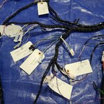
I have ID’ed a goodly per centage of the terminals on the new harnesses. I found I did not need to tag every item; by tagging a major component, the others would simply fall in place . . .


20210703_145515.jpg
So – I turned my attention to another element that needed to be done before I sent the car to the paint shop: stripping carpets and cleaning the floor.

After 4-5 hours I had nearly every carpet and under felt out and attacked the coating on the floor – wrong move.

So here’s here debris: I know – I know: don’t throw away anything.

Don't Throw Anything Away.jpg
Found some interesting items.

  • I now know the EX was not just a complainer (well . . . ). It’s possible the plug came out when the body shop stripped out the passenger side carpet / underfelt, but it appears she had a hot-air jet right at her ankles. Poor thing.

Found the reason for the hot passenger ride.jpg
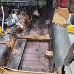
  • Years ago, I reinforced the passenger foot well cuz either the panels were not available, I could not afford them at the time, or they were available but (in pre-interweb days) didn’t know how to find them. On the floor you can see the patch where a small rust hole had developed and on the vertical end cap, the angle iron that was cut and shaped to fit the outboard edge.

Angle Iron Reinforcement and floor patch.jpg

At the end of the day, the floors were pretty clean.
Drivers Footwell and edge of Trans Tunnel.jpg

Passenger Floor and Tras Tunnel.jpg

I have decided NOT to strip the trans tunnel for several reasons: (1) there are no replacement harnesses available (at least that I can find) for the hand brake light, the cigar lighter, etc; (2) the original coating is surpringly intact; and(3) the original plugs are intact (with one glaring exception). I was gonna put DynaMat (or similar) on the floor and still will – just not on the tunnel. I should say “not of the “interior side” of the tunnel. I plan to apply DEI self-adhesive heat shields on the exterior side of the tunnel as well as hat thick closed-cell foam pad atop the transmission.

I also plan (right now) NOT to remove the factory original coating of the floors. I started to (in a corner behind the driver’s seat), but when I heated it enough for the gasket scraper to remove it, I discovered absolutely pristine sheet metal. I also discovered there is (apparently) several metal-pronged body floor plugs. I am inclined to leave well enough alone.


Leave well enough alone.jpg


QUESTION: once I clean the fuzzies from the underfelt off the floor coating, will the DynaMat (or similar) stick to it?

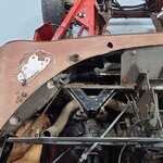
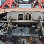
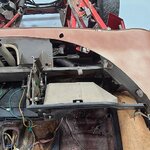
I have stripped much the harnesses from the engine bay. Two harnesses loop around the interior curve of the horseshoe frame and I still need to unbolt those fasteners. Still need to attack he wiring on the fuses . . .

Bulkhead Harness meets Engine Harness.jpg

End of one harness.jpg


A-C Harness Exits Drivers Side Footweel.jpg
 
OP
C

Craig Balzer

Well-known member
Joined
Sep 21, 2005
Messages
867
Location
Colorado Springs
Well – the last major wiring harness is now out of the car (there are still two harnesses in the engine bay; both follow to horseshoe frame and are covered in grease – a job for another day). I was correct that once I unscrewed the four fuses boxes and ALL the grounds and harness clips, the bulkhead harness unthreaded from the dash board in one long piece – just like the gauge panel harness.

Some of the harness clips were in real treat to undo.

As usual – a coupla of happy snaps to commemorate the event:

3ec351227ad12e3e9780e55d46aabfc39dfa56be_2_500x500.jpg
Close Up - Passenger Side Fuses3024×3024 2.2 MB


5a06f7e194c2a17c2643b789addbc9fb54f932b3_2_500x500.jpg
Close Up Harness Clips Holding Bulkhead Harness to Fuse Panel3024×3024 2.15 MB


This harness clip was fun; I had to thread a 5/16" wrench onto the hidden bolt head and loosen the
nut:

e248bcaeaf9866c97d812234aa82fe5220030ff2_2_500x500.jpg
Close Up of next-to-impossble Harness Clip3024×3024 3.64 MB


1471471aadf96515a0b7c2e48271049dc4fd6be9_2_500x500.jpg
Fit of hardura shield behind fuse blocks3024×3024 3.6 MB


2342416652a6ec39fe4b232422c4b4d9eb64ad32_2_500x500.jpg
Grey Flasher Can Mounted to HarnessClip on Passenger Fuses3024×3024 1.34 MB


The money shot(s)

637b1fe416275742fc49665a77bf5b79c482eb90_2_500x500.jpg
Driver Side of Dashboard Without Wiring Harnesses3024×3024 1.41 MB


18bba31d421eeb125964666395b0b993f7b2817c_2_500x500.jpg
Center of Dashboard Without Wiring Harnesses3024×3024 1.38 MB

I still need to figure what these last four are for??


31d84708279260d5465f24dfbf8e38c131bb5985_2_500x500.jpg
Passenger Side of Dashboard Without Wiring Harnesses3024×3024 1.22 MB


The real treat was wrestling with block connector for five minutes and a channel lock pliers only to find a PO found an easier solution. No idea where these wires go nor what they power . . .

42629d8745575a6f2d57a5a9449748e257d1e168_2_500x500.jpg
20210709_1452253024×3024 2.38 MB


The greasiest part of the Jag with 2 wiring harnesses running around the horseshoe frame

d969f1ecce485161a26a91d76b9e25c1eb30aeef_2_500x500.jpg
 
OP
C

Craig Balzer

Well-known member
Joined
Sep 21, 2005
Messages
867
Location
Colorado Springs
I had decided NOT to remove the evaporator until . …

  1. I realized I purchased all four replacement A/C hoses
  2. I needed to clean up the firewall on both sides
  3. I had come this far and if the A/C didn’t work, I’d be pissed at myself
It turns out the decision was made for me. When I finally figured out how to remove the left and right sides of the dashboard, the only thing holding the evaporator in place was the two A/C hoses and the three drain lines. All I had to do was unscrew the grounding strap and the evaporator was out.

2c8042f633cf0a7d7d31964b7165d29a25230c3f_2_500x500.jpg


57b4acf87869acc40b7a5ff67dd1b73859a75834_2_500x500.jpg


78100d5ba5167baad6d9b272ccdb3645cf71fd74_2_500x500.jpg
I have since removed the A/C drier and both A/C hoses


a1822021867094e5ad53e732524a62015a18991b_2_500x500.jpg

I also spent an hour ~trying~ to pull the fuel tank. I detached the wires for the fuel gauge, disconnected the two fuel lines atop the tank, and removed the three bolts holding the tank in the boot. BUT I was singularly unsuccessful in detaching the filler hose. I was able to move the hose up/down about 1/2", but not near enough to get it clear. That'll be my area of focus tomorrow.

Major items I still need to strip off are the aforementioned fuel tank, upper steering column/wheel, and steering rack. I realistically expect to transport my Jag to the painter late this month.
 
Last edited:

jbrentd

Well-known member
Joined
Jul 8, 2015
Messages
1,039
Location
Northeast Oklahoma
Sorry I'm late to the game here, but you have done an awesome job on your place! It's nice to see you're finally able to put it to its intended use...working on the cars. The Jaguar project looks like a lot of fun and I look forward to following along as you restore it.
 

Jayman17

Well-known member
Joined
Feb 6, 2017
Messages
3,814
Location
Seattle, Wa
Craig, it’s been quite awhile since your last post, just wanted to check in and see how you were doing. I hope the project and shop are getting worked on and all is well with you.

Jay
 
OP
C

Craig Balzer

Well-known member
Joined
Sep 21, 2005
Messages
867
Location
Colorado Springs
Jay
Thanx for checking up on me. I'm fine and have continued to move forward (slowly at times) but with forward movement all the time.
I stopped posting cuz after a few months of updates I had precious few responses so I figured people, while they were interested in the garage build and were interactive about it, they were not so much interested in the restoration of a car very few could relate to.

It would take a while but I could blitz this thread with the months of progress and hurdles, but I just don't believe it would be of interest to many Garage Journal-ists. Thoughts?
Craig
 
To avoid these ads, REGISTER NOW!

Jayman17

Well-known member
Joined
Feb 6, 2017
Messages
3,814
Location
Seattle, Wa
Well I can see where you might be discouraged by a lack of responses but another way to look at is that your posts are a record of your restoration and may prove to be valuable in the future. Either to show a potential buyer what you did or for personal reference.
I know that I find restoration builds interesting but don’t often comment because I know very little about that type of work and it is over my head.
Glad to hear you are using that great shop and are making progress. :beer:
 

kwyjibo

Well-known member
Joined
Apr 8, 2008
Messages
743
I might be biased, but I enjoy seeing other peoples projects - garages, cars, bikes, houses, tools... anything. For whatever reason during the covid shutdowns I cut back on all my web browsing and only recently started going back online more frequently. I wouldn't take the silence as an indication of general interest because I've noticed that a few forums seem to be quieter lately.
Keep the updates coming!
 
OP
C

Craig Balzer

Well-known member
Joined
Sep 21, 2005
Messages
867
Location
Colorado Springs
OK guys -- I'll get you caught up on my progress.

The weekend of 17/18JUL21 – I extracted the fuel tank and upper steering column with steering wheel.

I ended up cutting the rubber filler tube. The first three rounds of 5-7 minutes each went to the fuel tank. Could not find he magic angle / combination of curse words. THEN – I removed the drain bolt from the bottom of the sump. It didn’t amount to more than a 5/16" of thickness – and rounds 4 and 5 still went to the tank. Then the magic incantation worked and the tank literally fell out (well – after losing the first 5 rounds, round 6 occurred without fuss or fanfare).

5028382972e45758649170c6008259c8f3b698c6_2_500x500.jpg
20210718_1547143024×3024 1.97 MB


The steering column was pretty straight forward – only the u-joint pinch bolt proved a challenge – up-side-down in the footwell again was not fun.

cc7023edd94b35b7cc814b3ec4d7c001cb32f648_2_500x500.jpg
20210718_1546593024×3024 1.62 MB
 
OP
C

Craig Balzer

Well-known member
Joined
Sep 21, 2005
Messages
867
Location
Colorado Springs
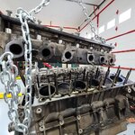
It was a month before I made any significant progress on my Jag. was messing with the 2x 4-bbl carbs on my 1965 Buick Riviera Gran Sport.

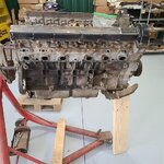
On 21AUG22 I pulled the water pump off the V12 engine in prep to send it to Coventry West for rebuild. Getting the last 4+" bolt out was an adventure in patience – two days. It was coated with black gunk that worked like a glue. Finally got it out by judicious use of a pry bar behind the aluminum water pump and a cordless impact driver: gently squeeze the trigger while gently prying behind the pump.
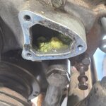
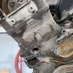
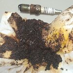
That was troublesome enough – what I found when I extract the pump really rang the bell. The photos show the crystalized coolant I found. It was soft enough to be easily removed with a screwdriver and paper towel – mostly. Some of it was compacted in the pump.

This is what happens when you leave the coolant in the engine and park the car in Phoenix for 13 +/- years followed by 18+/- years in the high-dessert plain that Colorado Springs sits on.

The impellor is packed with this **** and frozen. Does this make it beyond rebuildable?
Will the crystalized gunk be found throughout the block? If so, how do I clear it up?


6ff8b884fd22947671abdd6016579f9b15032923_2_500x500.jpg
Crystalized Coolant in pump cavity1920×1920 251 KB

cd38c877dca5335d231f3fb12e9f807b61e1a83f_2_500x500.jpg
Crystalized Coolant in timing cover1920×1920 674 KB

d536dd8f920f51f836f2507dc9685005f7488e50_2_500x500.jpg
Back side of pump1920×1920 570 KB

It turns out that all I needed to do to free the impacted water pump was place it in a pot of boiling water. Converted the goo back into liquid coolant.
 
Last edited:
OP
C

Craig Balzer

Well-known member
Joined
Sep 21, 2005
Messages
867
Location
Colorado Springs
A few days later (late AUG 21) I undertook the removal of the torsion bars in prep for getting the car to the painter. He would need to remove the engine frame sections (four pieces in all) to properly apply paint.
It turned out this was quite a procedure since the engine was out. I needed to apply an equal amount of weight to the front of the car to take the stress off the torsion bars so I could remove them. I bought a pair of over sized turn buckles to hold the suspension in a position close to the original:

Installing the turn buckle on the passenger side was quick and easy – there was no tension left in that torsion bar. The hard part was driving the torsion bar through the splines. A coupla shots of PB Blaster and Bob’s your uncle.

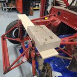
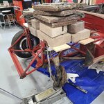
I finally worked up the courage to attack the driver side. Everything progressed just fine until I went to compress the torsion bar. With the engine out I needed to replace that weight; just didn’t know how. A quick consultation with a friend who is a retired Jag mechanic gave me the guidance I needed to proceed: a wide board across the side frames and tons of weight.

The story is in the photos/captions

7acebd19e1b9182f57dfbdd0370edb8c95888514_2_500x500.jpg
1 One board with 57 pound block of concrete was a bit short1920×1920 353 KB

bfa517133b8c815dfa1eb4d65af7a3d7affa2cfd_2_500x500.jpg
2 Top Shock Bolt Still Pinned by Tension on Tosrion Bar1920×1920 248 KB

2c040b29b00da308b92231fe904bf99b0a874c47_2_500x500.jpg
3 Finally Stacked enough pacers and Concrete Blocks to Compression Shock -524 pounds later1920×1920 558 KB
"pacers" in above caption ought to be "pavers"

e61ee4e82f0f1e58fed7bcc9905ac44e5b8caa60_2_500x500.jpg
4 Successful Extraction of Top Bolt WITHOUT Explosive Releasse1920×1920 335 KB

22682ef7d1a31e1c475b97a8600e07f6ec6fe4ed_2_500x500.jpg
5 Remove Schock - Install Turnbuckle1920×1920 614 KB

6de9706d58f290e06074e0a1fa7752c6bef51c4d_2_500x500.jpg
6 Turnbuckle set to 19 1-2 Inches (Bad Amgle makes it look longer)1920×1920 330 KB


I moved some of those pavers / concrete slabs 2 and 3 times. That puddle of goo on the couch is me.
 
OP
C

Craig Balzer

Well-known member
Joined
Sep 21, 2005
Messages
867
Location
Colorado Springs
Early SEPT 21 was spent trying to remove the side window lifting mechanisms with scratching the car or breaking the window glass. That process was slowed a lot when I threw out my back in the process. No photos -- nothing much so see.

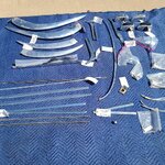
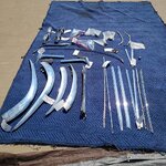
I decided to use a chrome shop in LA. Two reasons: I had seen the results of their work at several car shows and -- more importantly -- they visit three major car shows in Colorado three times throughout the year.

Later in September, I made the trip to a major car show in Loveland – about a 2 hour drive due north on I25 through Denver to link up with a chrome shop from LA, California. Every year they travel to 3 major shows in CO: Feb/Mar in Denver; June in Pueblo; and Sep in Loveland. You bring your pieces to them at one show and they are ready at the next. No shipping charges and no 300 lb FEDEX gorillas “handling” your stuff.

I didn’t drop off much but the invoice totaled $3,800. The price for each piece sounded very reasonable – it all adds up.

371f03c09e53e311f1bb1627616e2827da08f58f_2_500x500.jpg
20210911_1326231920×1920 855 KB

ceff5d26a4f13ea1c6c1a3f902981647faf99d1c_2_500x500.jpg
20210911_1326331920×1920 874 KB
 
OP
C

Craig Balzer

Well-known member
Joined
Sep 21, 2005
Messages
867
Location
Colorado Springs
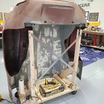
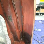
I spent several weeks removing the asphalt undercoating from the bonnet in prep for painting and in search of any uncovered rust. No rust found. Oh yeah -- I also built a mounting frame to hang the bonnet from. Keeps it out of the way and makes moving it to the painted easy too.

580bc77ca299d751458f4481354110afe42f8b27_2_500x500.jpg
1 - Bonnet Stand Overview1920×1920 376 KB

67c737cf64d41a104025111a6939c3315ecb198d_2_500x500.jpg
4 - Driver's Side Mid-Point of Inner Fender1920×1920 348 KB

b6206003ae63b3069ac1b9d8c3d2f711008cc115_2_500x500.jpg
9 - Passenger's Side Mid-Point of Inner Fender I1920×1920 333 KB


I had the chassis and bonnet ready for the paint/body guy to pick it up.
d63665ff2729f3a6607d82ff88db33939423ef5b_2_500x500.jpg
1 - Prepped for the move to Paint & Body Shop I1920×1920 326 KB

He and I loaded it (the weather cooperated for Colorado in early October):
42507321aba2f4c39d89307af319f356f159b7d3_2_500x500.jpg
3 - 06OCT21 Loadoing the Jag1920×1920 567 KB


The other piece of good news was the delivery on 05OCT21 of the single largest eBay purchase I have made:
ce4f04bc0550e4dd70a800d867434c1aa524ba51_2_500x500.jpg
1 - Crate was delivered on 05OCT211920×1920 434 KB

2b3dfef6d1ca1373dbafde6a5b55eb5cc74bf8bf_2_500x500.jpg
3 - Crate Opened1920×1920 377 KB

The short block came with (obviously) 12 pistons, cylinder liners, connecting rods (NLA), as well as 24 connecting rods bolts (available but at $27+ each), and 1x crankshaft. Obviously a bunch of studs. No oil pan, though.
There is still evidence of the cross-hatching on the cylinder walls and, more importantly, I can freely turn the crankshaft (and gleefully watch the pistons move up/down).
 
OP
C

Craig Balzer

Well-known member
Joined
Sep 21, 2005
Messages
867
Location
Colorado Springs
Now the bad news.

In addition to finalizing the chassis for paint, I started the basic disassembly of the original engine. I removed the 4x carburetors months previously to send them out for overhaul -- you can see where the side mount carbs would have been attached.

23873dd7fe07f3a6d1d8fe4c4f578cbeeee2bcac_2_500x500.jpg
20211004_1558461920×1920 440 KB

540bbcdc69a9538734fb151ab246ec31c62adab6_2_500x500.jpg
20211004_1559291920×1920 489 KB

3216a6f30a85a30f5de960ab42d0c7f27bbbd3ab_2_500x500.jpg
20211005_1605491920×1920 368 KB

41ebdf2ded6c1f5334e0017a02cd74174c25bd3b_2_500x500.jpg
20211006_1359581920×1920 422 KB

2ce80a753d0a8a3ebf9834101876b43df5ae739d_2_500x500.jpg
20211006_1400081920×1920 398 KB


In the process of disassembly I was unable to remove the distributor. The Repair Manual says to turn the engine to TDC, but I’m pretty sure that is only to ensure proper timing when reinstalling the dizzy – has nothing to do with extraction. I reasoned that the jackshaft was not turning preventing the removal of the distributor (problem 1).

So, after pulling the plugs, I tried to turn the engine with a 1/2" drive breaker bar. That is when I bumped into problem 2 - I believe the engine is seized (all the more so since I know the resistance I encountered when turning the crank/piston on the spare block).

I was successful in loosening the passenger side head nuts after letting them soak for 24 hours in PB Blaster. I sprayed PB Blaster into the cylinders to hopefully loosen the pistons/rings/whatever was stuck. NO JOY
 
OP
C

Craig Balzer

Well-known member
Joined
Sep 21, 2005
Messages
867
Location
Colorado Springs
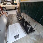
I got the V12 Head Removal Tool from the Jaguar Club of North America's tool lending closet. Turns out this is THE only tool in their lending closet that is NOT an official jaguar tool. Pretty Cool.
https://discourse-cdn.jag-lovers.com/original/3X/3/4/34502ae0704b1d6e852dffec0bfc57a702177ed7.jpeg
060da22f2f5269da2802026a8dcdd78b25deec91_2_500x500.jpg
JCNA Head Removal Tool I1920×1920 282 KB

52bf295b0415e82a0d7096ce3454de5262665d0d_2_500x500.jpg
JCNA Head Removal Tool II1920×1920 376 KB

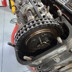
I have continued to remove small bits and stuff off the engine. It took a 30-minute wrestling match to release the tension off the large chain tensioner.

c4830b56f598b6306f466121e5e02df242e93239_2_500x500.jpg
1 - Overview of Time Tensioning Adjustment Hole1920×1920 585 KB

33a5dd4252f027b6ea000c8dfec028c7978cf98f_2_500x500.jpg
2 - Timing Chain on Gear1920×1920 285 KB

The tensioner is looking “like new” from this limited perspective – I hope the rest of the tensioner is as good (replacements are $375):
0094d1ba6ba698f163772d8229531dea220e9eb9_2_500x500.jpg
3 - Looking Down cam Gear at Timing Chain and Tensioner1920×1920 233 KB
 
Last edited:
OP
C

Craig Balzer

Well-known member
Joined
Sep 21, 2005
Messages
867
Location
Colorado Springs
In mid-November 2021, the paint guy called – he needed door latching hardware and boot latch/catch to properly set both.

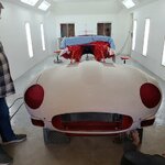
My Jag was in his paint booth on jack stands
dbac62f8421728c10a6374b86f2b4c0730f4e831_2_500x500.jpg
Body in Paint Booth on Jack Stands 3-4 front view1920×1920 261 KB

a2b84148663beeddfca910d447403db8990fc7c0_2_500x500.jpg
Body in Paint Booth on Jack Stands - front view1920×1920 271 KB

3f5fd58b153e42743cfcb263530ec4a058a1434a_2_500x500.jpg
Boot Lid1920×1920 402 KB

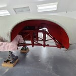
This photo shows the left and right side frame. the horseshoe shaped connector that ties them together, the triangular piece that holds the forward mounted bonnet, battery tray and 2x head light scoops (also some cross bracing that links the frames to the chassis underneath the car
862dedff72c641e79deb38bcf81ae95bcb9d50e8_2_500x500.jpg
Frome Rails Off II1920×1920 419 KB


This **** is getting real.

I instantly grabbed both side rails and inverted them – twice. I did not hear one bit of rust tinkling down the inside of the tubes (no rain stick noises). When I had the engine bay painted in 1988 I tested the frame rails and heard only a minimal “twinkling”. No worse for the wear.
So -- I do NOT need to replace the 4x frame elements (that rust from within)
So – that's is $10,000 I can employ elsewhere . . . I have some ideas.
 
OP
C

Craig Balzer

Well-known member
Joined
Sep 21, 2005
Messages
867
Location
Colorado Springs
Also in Nov 21, I discovered my dogs were barking pretty good at the end of the day. So, I picked up 6 very thick (7/8") 8’x3’ mats that are placed where I have discovered I end up standing a lot.

  • 2 in the Dirty Room (the blue tape X on the wall is were I intend to drill through the wall to run the pipes to distribute compressed air)
  • 1 each in front of my 2x 8’ Bowling Alley wooden benches
  • 1 each in front of my 2x 8’ Stainless Steel benches
8fd06eee695efe537c95b15bbd9cedcb3ecb3cc6_2_500x500.jpg
20211024_1516431920×1920 358 KB

d9670ccf059968dab3280bf581408d15c1a86402_2_500x500.jpg
20211024_1512431920×1920 265 KB
 
OP
C

Craig Balzer

Well-known member
Joined
Sep 21, 2005
Messages
867
Location
Colorado Springs
This stage of disassembly of the engine was particularly daunting. In preparation to pull the heads, I needed to remove the cams
which requires me to separate the cams from cam gears (and timing chain).

Ordinarily, a pretty straight-forward task: loosen/remove 1x 9/16" bolt securing the gear, rotate the crank to uncover the next bolt – lather-rinse-repeat until all four bolts (and the two lock tabs) are removed.
BUT
I still can’t rotate the crank (frozen rings and/or pistons or both).

Removing the first 2 bolts of the chain gear was easy - they were fully exposed and above the top of the cam cover - ratchet/socket and done; easy-peasy. Removing the third bolt was a challenge (wrench was able to loosen the bolt 1/2 flat at a time); removing the fourth bolt was an exercise in frustration, patience, and endurance (loosen the bolt 1/3 of a flat at a time while using a stout screwdriver to pry the offending part away from the bolt head).

But . . . success

9fdbbfd836e606821f11b706df52ce0acd0b9288_2_500x500.jpg
20211106_1533101920×1920 399 KB

I also removed all the cam bearing bracket nuts relieving tension on both cams
aef17559f4a7e2101f2ace26a064b229fc94617c_2_500x500.jpg
20211106_1532241920×1920 247 KB

e50cbfc2626f8768a9c6e03234376e51db1c646e_2_500x500.jpg
20211106_1532301920×1920 362 KB


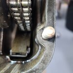
The chain tensioner looks to be in fine condition. Unfortunately, the camera pulled focus on the chain rather the surface of the tensioner. There appears to be evidence of the chain rubbing against the cam cover,
8bacb39fcb2c3b6fd0ef49f01de6c5ae467c18e0_2_500x500.jpg
20211106_1514591920×1920 259 KB


I have been advised that (1) it is a toss-up rather I can extract the tensioner intact - they very often break during removal and (2) even if I succeed in extracting the tensioner in one piece, there are better-made replacements and I ought to replace it, regardless.

After three hours of yardwork (unseasonable warm temps today) and the above wrestling match, I was tired enough that I decided not to remove the cams cuz I didn’t have a plan in place to properly store the bearing saddles. An egg cartoon is insufficient cuz there are 7 cam saddles per cam. Need a time-out to approach the next step with a clear mind and plan to hold/store/not mix up the bits.

Once the cams are off, I’ll apply the v12 head removal tool and more PB Blaster – – and pray.
 
OP
C

Craig Balzer

Well-known member
Joined
Sep 21, 2005
Messages
867
Location
Colorado Springs
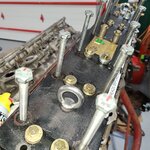
Let me explain how the head removal tool works. The long bolts pass through the tool and press against the tops of head studs (see first photo below).
The row of threaded holes down the middle of the tool accept teh 5/16"-18 Grade 8 bolts that thread into the holes in the head that held the cam brackets.

I made some sleeves by cutting ~1" segments from a 1/2" pipe and went to Ace Hardware for 5/16"-18 Grade 8 bolts. In the photos below you’ll note stacks of washers under some of the bolts cuz I couldn’t tighten them before “bottoming out”.


355330e35a76421372c4804aa07cfc8c12c45050_2_500x500.jpg
1 - Plate in place, bare studs below aligned with 17mm bolts in plate1920×1920 695 KB


Here are the pipe segments in place:
da84ce0a52f73ee569883124863c0616739c8c07_2_500x500.jpg
2 - Plate in place, bare studs below aligned with 17mm bolts in plate and 12 inch pipe segment on stud II1920×1920 630 KB

And here are the grade 8 bolts attaching the tool to the head; I also marked the bolt heads with permanent marker to better track how much I loosen each turn/ after running up and down the head 16-20 times, it's easy to lose track:
a58368a8396a2216ac12ad6bf60764e0321f8ae0_2_500x500.jpg
3 - Cam Bearing caps removed and I used grade 8 bolts in their stead1920×1920 408 KB

054de89c6027d801f52dc867149f4d0661e6dd45_2_500x500.jpg
4 - After 10 minutes of tightening 17mm bolts onequartervturn at atime1920×1920 592 KB

764fc5da019cd19334fd410f49adc045381f1209_2_500x500.jpg
5 - About an inch of clearance1920×1920 489 KB

Notice the “tilt” of the head? I worked hard to maintain an even lift to avoid the head from jamming/binding on the studs
a7f104cd3b71b220b522de12603eb22dcbb10b92_2_500x500.jpg
6 - End of the Day, on day 1 - side view1920×1920 505 KB

c8c37e53199b2f53d345a9b83cff2cd48f5f884a_2_500x500.jpg
7 - End of the Day, on day 1 - end view1920×1920 429 KB
 
OP
C

Craig Balzer

Well-known member
Joined
Sep 21, 2005
Messages
867
Location
Colorado Springs
The Next Day
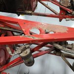
Turns out I wasn’t far from pulling the head yesterday. Had it off in less than 30 minutes from today’s start.
9f8f7b2d8a37e41537dad07e07ebcb8b3981ddd1_2_500x500.jpg
2 - The driver’s side head came off at 121400NOV211920×1920 433 KB

Thus endth the GOOD NEWS.
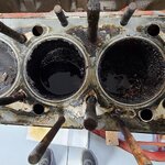
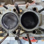
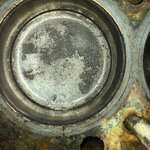
At least I’m pretty sure I identified the reason I can’t turn the crankshaft.
WARNING - the rest of this post is photo heavy.
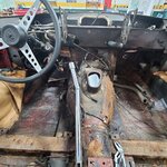
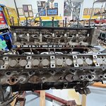
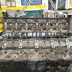
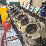
First – for comparison sake – the next 3 pix show the pistons tops/cylinder in pairs (front of block to rear).

2d44bd5dc00cf6c1bdaf161799208668d839dc96_2_500x500.jpg
3 - Forward pair of cylinders1920×1920 339 KB

That puddle of fluid is PB Blaster. I believe the granular stuff is crystalized coolant. More on it in a bit.
efe0aac9148f90ec61c93f10e53dbbab3d4e7071_2_500x500.jpg
4 - Center pair of cylinders1920×1920 366 KB


e042d3bb2fcead93082921717fef57d918bc0341_2_500x500.jpg
5 - Rearward pair of cylinders1920×1920 396 KB

This photo was taken after I used a syringe to **** up the fluid (PB Blaster?) leaving behind a bunch of stuff
4600e6cf4f9f8acd98799eb5c1c99f04db421ba2_2_500x500.jpg
9- The offending pair1920×1920 469 KB

This is 80-90% of the stuff I pulled out of one cylinder
3b77a96f6c2cc2179b59204d3aa252b98610db2b_2_500x500.jpg
15 - The debris from cylinder 41920×1920 548 KB

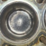
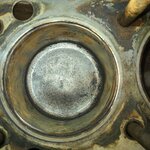
The following photos are close ups of the 2 offending cylinders - - the captions provide details
4600e6cf4f9f8acd98799eb5c1c99f04db421ba2_2_500x500.jpg
9- The offending pair1920×1920 469 KB


f17923ec7810f1d5e2da46fae48c7f257427c86d_2_500x500.jpg
11 - Close up cyl 3 II1920×1920 766 KB


317d312150248349d83559828a15bbc91dc9c4b2_2_500x500.jpg
12 - Close up cyl 4 I1920×1920 772 KB


c660adbca325ab404f2f2235c1713f323feb0161_2_500x500.jpg
14 - Close up cyl 4 I1920×1920 923 KB

THESE ARE THE QUESTIONS I ASKED ON A JAGUAR FORUM: So – is there a chemical I can spray in there to break up this stuff? It is really stuck to the piston top and cylinder walls. Almost like very coarse sand paper or even stucco; it seems to be bounded to the cylinder/piston top. I didn’t want to do much scrubbing for fear of scratching damaging walls and tops. Or are these cylinders/pistons beyond salvage? Will I be able to get them out of the block.
I didn’t see any witness marks on the head gasket indicating a coolant leak into these two cylinders – but what else could it be? The dark stain on the top of the photo of the head gasket of the middle pair of cylinders is – I believe – from PB Blaster leaking down the stud.
Any ideas or thoughts?

SPOILER ALERT - I ended up buying 12 pistons and 12 cylinder liners
 
Last edited:
OP
C

Craig Balzer

Well-known member
Joined
Sep 21, 2005
Messages
867
Location
Colorado Springs
The Next Day (in late Nov 21)-- I removed the other head:

Time to fess up – removing the second head didn’t go very well at all. It clearly falls into the “Don’t let this happen to you” category!

The first head came off without issue – while the Jag has sat for ~30 years, the engine had only been driven ~10,000 miles since the previous rebuild in 1988. It came off clean as a whistle without much fuss or ado.

The second head was another story. I was overconfident based on the first head literally popping off. I was very attendant to maintaining a level lift looking at the side of the head. I measured the head/block gap 4-5 times and I maintained a 3/16" to 5/16" differential as it lifted. I did NOT attend to the lateral lift and this was the result.


9d6a554c7c996906104a141413c0256e4ff1e826_2_500x500.jpg
20211114_1108031920×1920 294 KB


Yes, that row of studs has a bend to them. I didn’t take any photos of it but there was still 3/4" to 1" of thread inside the head.

In an effort to free the head:
  • I tried a dead blow hammer striking down on the “uphill” edge on the top of the head
  • I tried a dead blow hammer/2-pound sledge striking up on the “downhill” edge on the bottom of the head with a 2x4 for a cushion
  • I tried a pry bar between the head and block with 1" thick wooden strips protecting both faces to pry the downhill edge upward
  • I tried a dead blow hammer striking on the exhaust manifold mating face (cushioned with a 2x4) to try to tilt the head inward to the V
  • I tried rotating the engine/head on the engine stand both clockwise and counter clockwise in an effort to relieve the strain on the studs (I think there was too much bend in the tip o the studs for this to be effective)
  • I tried using the cherry picker to lift the head off (on various angles of block tilt on the engine stand) but all I did was lift the engine and engine stand
    All with an effort to dislodge the studs stuck in the head or tilt the head to free it from the studs. None of the above approaches was gonna free them from the head.
After two days’ effort, I had to resort to the last option: Sawz-All the 7 worst studs. Head swung free and I was able to remove the stud remnants from the head easily with the head on a bench; haven’t tried to remove the stud remnants from the block yet (my focus was on returning the tool to the Jag Club of North America inside the 10-day usage time frame) but they ought to come free easily enough as the bend was in the head-end of the studs. Gotta leave something to do tomorrow.

So with this debacle behind me, and having picked up a gallon of Minnich’s Metal Rescue from Home Depot, the next phase of the assault on the block is to decoke (or de-whatever is chemically bonding the piston to the cylinder wall) the 3-5 cylinders that are frozen with an ultimate goal of using a breaker bar and 1-5/16" socket to rotate the crank.

Having too much fun.
 
Last edited:
OP
C

Craig Balzer

Well-known member
Joined
Sep 21, 2005
Messages
867
Location
Colorado Springs
These are the stud fragment that came out by hand (no tools).

e4f5e5dd8d8f4ec1775cc64530e9eb15d9d2fa59_2_500x500.jpg
20211116_1108511920×1920 279 KB


The one stud fragment that is unbent was from a different row of studs and wasn’t nearly as deep in the head as the others. Actually I cut the wrong stud – got lost in the forest of trees,

I was able to go from this

5e3c56740ff0320b12e40913b8a0d49317bdd151_2_500x500.jpg
1 -Passenger Head with 7 cut Studs1920×1920 413 KB


to this

33e4cb2e845d43f60424d91c805c765280a7fb22_2_500x500.jpg
2 - Passenger Head with 7 cut Studs 12 minutes later1920×1920 476 KB


in just over 12 minutes. I used 2 different pullers and more PB Blaster.

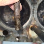
Most of the stud fragments came out looking like this

9337c3638df3421cf7f1942015d6aebe6e06996d_2_500x500.jpg
3 - Six of the studs looked like this when removed1920×1920 216 KB


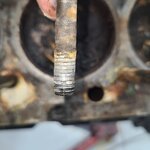
Unfortunately, one came out looking ugly:

d72c1b8c7232ccafdaac04cb8fa242794178c14c_2_500x500.jpg
4 - One came out looking ugly1920×1920 170 KB

I then spent some time with wire brushes on a cordless drill and cleaned up the piston tops and cylinder walls. I was surprised how much loose **** I vacuumed away.
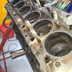
Here are some examples (they look even better cuz I cleaned 'em some more after I took the happy snaps):

45c31492e42d9d91a417bc8c2c6129e4a0be58d9_2_500x500.jpg
Driver Head Cylinder #11920×1920 445 KB

43b1ed9a3c6bea7708b76166248339089000a7e3_2_500x500.jpg
Driver Head Cylinder #51920×1920 635 KB


While I guess I shouldn’t have been surprised, the holes that came away the cleanest were the ones that had puddles of PB Blaster sitting them. Still gonna take some cleaning / heavy duty pressure to free them from the block. Likely will take them out as a unit and then press the pistons outta the cylinders; although that may be an exercise in frustration (I am getting close to being resigned to replacing all cylinders and pistons):

9a947c2832e3cbad8c8444476496c0ce4d4400b3_2_500x500.jpg
Driver Head Cylinder #31920×1920 470 KB

a69bdf4328fc753f4ac322079db23735fbf6a143_2_500x500.jpg
Passenger Head Cylinder #31920×1920 658 KB


I did unearth a little damage in one hole:

bcb47cf410d56092d312febd4cb24bf289a7cb93_2_500x500.jpg
Passenger Head Cylinder #21920×1920 642 KB
 
OP
C

Craig Balzer

Well-known member
Joined
Sep 21, 2005
Messages
867
Location
Colorado Springs
After all this BAD NEWS I deserved some GOOD NEWS

I was contacted by my paint guy - he needed some extra hands to re-attach the bonnet to the body and asked I return the cleaned up front suspension (I intend to cad plate the suspension but I didn’t have the time – used SOS Pads and steel brushes).
Here is what greeted me:
Frame sections painted and reassembled and the firewall painted

e1ceeac5dad68fa2b68516fc55aa1217422b8fd1_2_500x500.jpg
Front frames - left 3-4 view1920×1920 291 KB
Note the pivot bolts and plastic bushings on the floor


d0ecbf2396d8daa2e323d4252aba15cc6ac7ec29_2_500x500.jpg
Frontf rames -front on1920×1920 271 KB


6ede32345815ca522bf00f0a95a1c7837bb3fc50_2_500x500.jpg
Front frames - right 3-4 view1920×1920 280 KB

I brought a buddy and we unbolted the bonnet from the wooden frame I built and laid it on milk crates in front of the body

3f3cce063e084b1055163a8659f7d961137d8576_2_500x500.jpg
Bonnet removed from wooden stand and positioned in front of1920×1920 186 KB

and then he and I lifted/held the bonnet in place while the painter reattached the pivot bolts

c28b3737e5ea5c3cc70fa1d496315d29553d0aeb_2_500x500.jpg
Bonnet back in place1920×1920 211 KB
 
OP
C

Craig Balzer

Well-known member
Joined
Sep 21, 2005
Messages
867
Location
Colorado Springs
Now comes the finnicky bits: straight/smooth body panels, panel gaps and doors and boot lid fitting. On the body, there are three areas needing hammer/dolly attention:

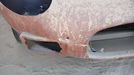
  1. When the initial body work was done in Phoenix in 1992, the car needed to be stored for quite a while. When moving it to long term storage, that body shop snugged the car too far forward on the trailer and a protruding bolt:
    afc8689692d01dfb0c1024a46f1cd9cb5a830d91_2_690x388.jpg
    10 - Close Up Nose Damage1920×1082 195 KB

  2. When trailering the car from Phoenix to COS in 2006/07, I put a tarp over the passenger compartment when weather threatened. One eyelet was centered on the body between the passenger compartment and boot opening and was flapping in the breeze. Rat-a-tat for 700 miles:
    1b7813bb1eed35ab056c31093e6a3f21c7ebf3b2_2_690x388.jpg
    14 - Rear View1920×1082 155 KB


0cb056734e7ec8a2579a694520799d8b8224a667_2_690x388.jpg
15 - Close Up Rear Scutle Damage1920×1082 99 KB


And I made a rookie mistake in the early days of lift usage. I placed a 5-gallon Home Depot bucket too close to the left rear of the car. When I lowered the car, the bucket crushed but not before putting a near-basketball-sized dimple in the under-pan behind the rear wheel. With the fue ltank out, this repair is in the too-easy category.
NO PHOTO AVAILABLE

None of these ought to cause the body man any issues, just some extra hammer and dolly time in the process.
Those are the only blemishes --no rust with which to deal
 
To avoid these ads, REGISTER NOW!
Top Bottom