To avoid these ads, REGISTER NOW!

Above 1200 Sq/FT Craig's Colorado Car Condo

Wokspaces above 1200 squarefeet.
OP
C

Craig Balzer

Well-known member
Joined
Sep 21, 2005
Messages
867
Location
Colorado Springs
Some miscellaneous get-caught-up photos

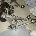
As I have stated, my intent is to cadmium plate a bunch of items (I have since decided to nickel plate the suspension pieces and found a plater 3 hours from my house). In the case of the suspension, my painter needed them to move the car around but couldn’t provide a hard schedule. So I temporarily delayed coating them and instead soaked them for 2-3 days in Berryman’s and then scrubbed them with SOS pads.

They came pretty clean except where the angles prevented me from “getting in there”.

6ea71e4f48fcc4700b27db1380a4a0ec72f58536_2_500x500.jpg
20211124_1006451920×1920 445 KB

dacbda4915b4bf1d54e1c0b8f9438c579a426e1b_2_500x500.jpg
20211124_1006541920×1920 530 KB


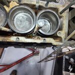
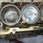
I also pulled off the head gaskets if only to take a see how bad the congealed / dehydrated coolant looked. I took 6-8 photos (mostly for my records) – here are the worst of them:

80a5bd27501106ddcd2d8d5237fc34a5b44a8fe8_2_500x500.jpg
20211124_1459031920×1920 458 KB

66b501f3d00358e80155d385dba2c5fb5ac7b757_2_500x500.jpg
20211124_1459151920×1920 406 KB

a3f249c91adbd66f77a7d5913e6f3e83052d930e_2_500x500.jpg
20211124_1500161920×1920 412 KB


Some of it is still wet (PB Blaster? – but how? if trickling down the studs I take that as a win; studs ought to come out fairly (cough - cough) easily) and some is dry. I’m thinking it’ll clean up nicely once I pull the pistons and crankshaft – – he said hopefully.

I also spent 6 hours resorting all the bits and parts I’ve ordered over the last 5-6 months. Having them in the boxes in which they arrived made no sense. So boxes and boxes became about 10 boxes: INTERIOR - ENGINE BAY - SUSPENSION - DASHBOARD – etc.
No photos – a dozen labeled boxes on shelves – pffft.
 
To avoid these ads, REGISTER NOW!
OP
C

Craig Balzer

Well-known member
Joined
Sep 21, 2005
Messages
867
Location
Colorado Springs
On 22NOV21, I helped the painter attach the bonnet as shown above and provided him with the bonnet latching hardware.
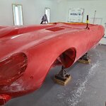
On 02DEC21 (9 business days later and one of those was Thanksgiving) I received a text message from him. All it said was “Your Jag is Red”

and he included a single photo – I’m at his shop tomorrow to take more photos
fc75af93937d7386269d1392ef1b7253756a66ca_2_666x500.jpg
20211202_1357281920×1440 136 KB


I am psyched.
 
OP
C

Craig Balzer

Well-known member
Joined
Sep 21, 2005
Messages
867
Location
Colorado Springs
The painter applied 3 color coats and 4 clear coats. At this point, he was wet sanding with 1500 grit paper:

2f3cb2796c5b7b4f99733bb50f4db413f5b74184_2_500x500.jpg
1 - Wet sanding with 1500 grit1920×1920 293 KB


dff32e09a169099d026867e25276396342897a88_2_500x500.jpg
2 - Left Front 3-4 View1920×1920 292 KB

d4ecb56ab967f89741ab9d3fbc858e49d1732e05_2_500x500.jpg
3 - Right Front 3-4 View1920×1920 310 KB

He said he’s going to wet sand with 2000 and then 3000 paper before buffing,


I focused some of my photos on the three areas of body damage
  1. BEFORE - Rub Mark From Bolt Head On Trailer; Jag was snugged too close to front of trailer
    59f8a458e9c4b4ca88d08dc86e99193194855e1d_2_394x499.jpg
    DSCN2179 (2)522×661 85.9 KB
    AFTER - GONE
    6d589eb2c5cd20549bb9438b3550cfdefdb7c191_2_500x500.jpg
    4 - Rub Mark from Trailering Phoenix FIXED1920×1920 219 KB
BEFORE - Photo Not Available – I lowered the car on my lift without checking placement of a Home Depot 5-gallon pail. I put a dent under the LR fender that was 1/3 to 1/2 the size/depth of a basketball.

AFTER

e153b1084748b50212f66a0467fc746ed34ef384_2_500x500.jpg
5 - Dent under LR Wing from HD 5-Gallon pail FIXED1920×1920 339 KB


BEFORE - This dent (at the mid-point of the rearmost panel of the passenger compartment – between the attaching points for the hood and the boot opening) was caused by an unfastened gusset on a plastic tarp I tied over passenger compartment when foul weather threatened while moving my Jag from Phoenix to C Springs. About the size of a hardball and 3/4" deep

1b7813bb1eed35ab056c31093e6a3f21c7ebf3b2_2_690x388.jpg
14 - Rear View1920×1082 155 KB

0cb056734e7ec8a2579a694520799d8b8224a667_2_690x388.jpg
15 - Close Up Rear Scutle Damage1920×1082 99 KB


AFTER - The metal was stretched such that the painter had to cut a slice in the middle of the dent, straighten the dent, and then weld the slice closed. I suspect a dab of Bondo was involved

c80c0d753b85e65a3d36769d45cddd8f4344fc0c_2_500x500.jpg
6 - Dent from Flapping Tarp Trailering from Phoenix FIXED1920×1920 233 KB


fd0cfaa7e0db8fc13341b3d755f7f09b4589ba44_2_500x500.jpg
7 - Dent from Flapping Tarp Trailering from Phoenix - side view FIXED1920×1920 116 KB


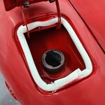
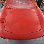
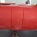
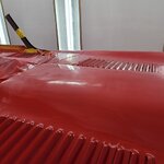
The next 4 shots (including the above shot of the repaired dent forward of the boot lid opening) focused on the gaps between body panels. (The captions tell the details.)


5aa681cd59d098e17bfe87148f9eb8963c154db6_2_500x500.jpg
8 - Body Gap FuelLid & Wet Sanding of Deck Lid While Filler Cap Lid is asyet Untouched1920×1920 127 KB

166cadf7af89dddfa8d4a91bc2d44e91de818436_2_500x500.jpg
9a - Under Fuel Cap Lid1920×1920 234 KB

873af12935a03417ecd7b758ca6a3f85ce2fdffe_2_500x500.jpg
9 - Body Gaps - Boot Lid1920×1920 235 KB

ab7e65a73db95e9193106fbc626d943ec485b761_2_500x500.jpg
10 -Body Gaps - driver Side bonnetg & Door vis-a-vis Body1920×1920 160 KB


4f739cb07d9b21502e7c2342436cdf8ce4e7fa38_2_500x500.jpg
11 - Very Minor Orange Peel on Bonnet Bulge1920×1920 148 KB


After the painter completes the wet sanding with 2000 and then 3000 grit paper and buffing, he still needs to paint some small bits: steering column shaft, sugar scoops, the cross bar on the horseshoe, 2x cross tubes under the spaceframes, etc.
 
OP
C

Craig Balzer

Well-known member
Joined
Sep 21, 2005
Messages
867
Location
Colorado Springs
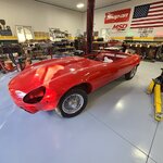
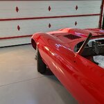
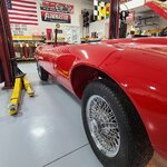
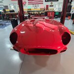
On Saturday 11DEC21 at 1:30PM the painter backed into the drive to my Hobby Shop and delivered my RED Series III OTS. To me – each photo looks new and fresh and different. I suspect that these photos will all look alike to most (kinda like watching (suffering through) your neighbor’s vacation photos/slides). So – sit back – take a gander – try to stay awake.
Each photo is captioned

3a8f25ee83973707138dd11a43a9955b03b83190_2_500x500.jpg
1 - I cleaned up so the garage was as clean and fresh as the Jag1920×1920 260 KB


cf4832f8b48099ad83502d7002732836a0a97e07_2_500x500.jpg
2 - It Home Its Red and it needs everythingput back1920×1920 262 KB


3265031c2c589e782119ccb482b0b90a162a7608_2_500x500.jpg
3 - Three Quarter Front View1920×1920 299 KB


db409f6d2abf6f88b06f5edac3213ed12c44ae77_2_500x500.jpg
4 - The Back End1920×1920 241 KB

This is one of my favorite shots: the powder coated garage door reinforcing rails are reflected in the red paint and flare upward/outward as they flow along the curves of the bonnet
ec2ecfaf9aaa921181fd36a6d05bf806adc54977_2_500x500.jpg
5 - The Reflection Lines are Nice and Straight1920×1920 200 KB


800b645b58931df8bcbb157588c1c8279b4d1eed_2_500x500.jpg
5a -The Reflection Lines are Nice and Straight1920×1920 254 KB


fb9ef2d0f5834a622721d4c0279d2a01d9e2c93e_2_500x500.jpg
5b -The Reflection Lines are Nice and Straight1920×1920 337 KB


d5231f5414c044b22bafef1b588d1cb8031eb15d_2_500x500.jpg
6 - Shut Lines Look Pretty Nice1920×1920 291 KB


1f83b992fd59a08de9527be91c0d822786f2db4f_2_500x500.jpg
7 - Now I Gotta figure out HOW TO INSTALL THE Sugar Scoops -- I didnt take them out1920×1920 285 KB


31e192d814df5e486c9c9cce1173b81d69e2fce4_2_500x500.jpg
8 - From Above1920×1920 335 KB


637114bde5cded0fb1567363df51e82350595555_2_500x500.jpg
9 - Behinbd - From Above1920×1920 282 KB


a9e22fcd6abd6a420c5a496b40ade6c326dcd9fb_2_500x500.jpg
10 - The Bonnet from Above1920×1920 195 KB
 
OP
C

Craig Balzer

Well-known member
Joined
Sep 21, 2005
Messages
867
Location
Colorado Springs
OK Folks -- that marathon of postings brings this thread up to Dec 21.
I'll take a breather and continue a bit later with my efforts since the turn of the New Year
Thanks for following along
Craig
 
Last edited:

Toolfool

Well-known member
Joined
Aug 22, 2011
Messages
4,982
Location
Tallahassee, FL
You have built an amazing shop. You also have some cool projects to keep you busy. Enjoying your documentation. Keep it coming. :beer:
 

jbrentd

Well-known member
Joined
Jul 8, 2015
Messages
1,039
Location
Northeast Oklahoma
The body work and paint turned out nice!

With regards to the crystalized coolant, not sure if you got an answer. I wonder if it has seen a mix of incompatible coolants over the years? I've used some of the cooling system flush products with success, in the past. It just take several rounds of fill/drive/empty/repeat to get it cleaned up.

1651776174590.png
 
OP
C

Craig Balzer

Well-known member
Joined
Sep 21, 2005
Messages
867
Location
Colorado Springs

GGB

Well-known member
Joined
Oct 26, 2011
Messages
388
Holy cow, Craig! Your Jag is on its way to being gorgeous! I admire your patience with the engine disassembly-that would have frustrated me to no end. Please keep us posted on your progress.
 
OP
C

Craig Balzer

Well-known member
Joined
Sep 21, 2005
Messages
867
Location
Colorado Springs
I admire your patience with the engine disassembly-that would have frustrated me to no end.


GGB -- you ain't seen nothing yet. Give me a few days to post my progress from Jan to today.

Spoiler Alert - the major issue with my engine was a $1,000 bill at my machinist to rectify
 
OP
C

Craig Balzer

Well-known member
Joined
Sep 21, 2005
Messages
867
Location
Colorado Springs
NOTE - I missed 5-6 weeks of work/updates. Jump to post #342 if you want to keep reading in chronological order. Then come back here.
Or -- just keep reading. The sequence of events isn't really on that necessary.


February 2022: Joe Curto, an expert in SU and Stromberg side draft carbs, finished the rebuild/restoration of my four carburetors. He needed to replace at least 1 float, at least 1 vacuum adjuster screw, several lock screws. I am sure there were more issues but these were the highlights. The carbs sat for 32 years unused in the AZ desert and the CO high desert plain.

He had called during the previous week and referred me to Rob Medynski (sp?) (*) whose expertise is rebuilding dizzies and converting them to vacuum advance. As part of the rebuild, Rob drills and taps a port in the proper location of one of the carbs to get the vacuum to the dizzy. Joe sent one of my carbs, after his rebuild, to Rob.

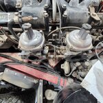
This photo shows the driver's side pair of carbs on the dusty, rusty engine
Drivers Side general.jpg

Each rebuilt carb was packaged in its own box, enclosed in a vacuum-sealed bag, and nestled in scrunched up newspaper. Very secure.

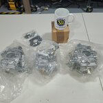
I unboxed each of the three carbs (Joe sent my Right Front carb to the guy doing the rebuild/upgrade of my dizzy to machine a port of the vacuum advance). Oddly - there was a fourth box smaller than the others. Hmmm – left over parts? (not likely) Return of replaced components (unnecessary). A Joe Curto Coffee Mug. Nice touch


e5950dc1241751d70f1b1685f1c3d1df134c24c8_2_500x500.jpg
20220214_1701351920×1920 245 KB


Each carb was labeled as to its position on the engine and the needle size – all three have B1CQ.
I only unbagged the one.

7a5f3bd27ac2e0b07efd268ea2b155daa8a72092_2_500x500.jpg
20220214_1703031920×1920 256 KB


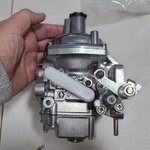
I’m not an expert but it looks and feels like Joe vapor blasted the carbs.
He apparently plated or cad plated the bell cranks and other small bits

63756176becd43fe089fb03c2105bb8337ecbf48_2_500x500.jpg
20220214_1703371920×1920 308 KB

e03f800a51dd6db96e32ec37e6e776b6d7b6046c_2_500x500.jpg
20220214_1703501920×1920 261 KB


If they work half as well as they look, I’ll be a happy camper.

Coincidentally, I paid the invoice for the dizzy rebuild/upgrade today. Ought to see those later this week.
And the Damper Doctor sent my harmonic balancer back late last week.
New parts are stacking up - - - - I need a bigger hobby shop.
 
Last edited:
OP
C

Craig Balzer

Well-known member
Joined
Sep 21, 2005
Messages
867
Location
Colorado Springs
A few days later:
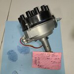
Got my dizzies back after being rebuilt and converted to vacuum advance. I sent my original and a spare picked up years ago.

fecc9cb6cc1e0ce0a63916c4787910b312cde443_2_500x500.jpg
Spare Dizzy1920×1920 242 KB


Each dizzy had a 3x5 card showing the advance:

RPM ----------ORIGINAL----------SPARE
400----------------3---------------------3.5
500----------------5---------------------5.5
1000--------------7------------------------7
1500-------------8.5-------------------8.25
2000-------------10--------------------9.75
1750--------------12----------------------11

Original said “Set 10 static or 20* at 1000 RPM”
Spare said “Set 10 static or 20-21* at 1000 RPM”

I was surprised at the degree of accuracy of the curve points – apparently 1/4*
 
OP
C

Craig Balzer

Well-known member
Joined
Sep 21, 2005
Messages
867
Location
Colorado Springs
01MAR22: I did turn a “corner” in that I put the first thing back on my Jag today.

One tip for (Series III owners only?? ) those removing/re-installing the wiper mechanism is NOT to try to wrestle them out either the left or right opening in the dash (the curve of the dash at the ends gets in the way). Purely by accident, I found out today that I could quite easily slip the ~3’ long mechanism into/under the dash through the center opening without risking the paint or bending the mechanism.


a361f239287aa13766a92e351a9916c690e5f9d8_2_500x500.jpg
20220301_1406591920×1920 358 KB

66b64eab5b5d57837b6c5cc8669434e536b366b0_2_500x500.jpg
20220301_1517121920×1920 329 KB

5cfb9156a7c61370a167455ae653fb8ce6b19492_2_500x500.jpg
20220301_1516571920×1920 182 KB


PS – Those small white dots are NOT areas with no/missing paint; those are remnants of the polish or final buffing compound the painter used, they are in tiny depressions in the lip of the body
 
OP
C

Craig Balzer

Well-known member
Joined
Sep 21, 2005
Messages
867
Location
Colorado Springs
09MAR22:
Speaking of moving forward and then backward.

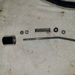
The small step forward was reassembling the emergency handbrake handle with newly chromed tube and release button.

FORWARD: after fumbling around for half an hour and squinting at the useless photos I took months ago, I figured out how the assembly went back together

BACKWARD: the small black plastic (or hardened rubber??) grommet-like thing split in half after only 50 years. Pretty sure I need it to have a functioning handbrake – but maybe not???.


9d77b12c2c7e9e194f7cc3102b7850b64ff2bc68_2_500x500.jpg
20220309_1802401920×1920 530 KB

This photo (above) shows the mechanism laid out in assembly order. The broken grommet-like thing is in the lower left corner - in halves. The rod fits inside the chromed tube (see bend). The spring is bracketed by the small washers; the nut adjusts the length of the spring (applying tension).


-o-o-o-o-o-o-


b9e8d2b83a12474c7bb5126c55d7abd4f198dcc5_2_500x500.jpg
20220309_1803261920×1920 356 KB

The chromed release button (threaded recess inside of it) presses down the rod (through the spring; the spring simply returns the release button to the starting position) which pivots a small pawl at the far end (not pictured) and releases the ratchet on the base of the e-brake handle, thereby releasing the e-brakes. For all this to work properly, the spring must be held in place on the rod.

I suspect others have had this problem -- still 06MAY22 -- trying to solve this one
 
OP
C

Craig Balzer

Well-known member
Joined
Sep 21, 2005
Messages
867
Location
Colorado Springs
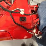
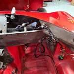
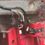
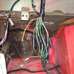
One of the major issues I'm struggling with (small in the grand scheme of things but it's holding up installing more wiring harnesses) is getting a special grommet over the main bulkhead harness to protect it where it passes through the firewall:

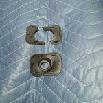
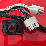
The following 5 photos describe my issue. About the only solution I can see is to cut the rubber piece at 6 o’clock to fit it over the wiring harness and then clamp the 2 plastic lock pieces in place.
Captions tell the tale:


de29cc2be83b063cbf13d13835d0a66cfc96d44d_2_500x500.jpg
1 - The rectangular hole in pssenger side firewall through which wiring harness passes1920×1920 242 KB


9f036b885bd7d8e7dd47e7dff000a2c5c5fb0d59_2_500x500.jpg
2 - All of this harness (from the left edge of the image to the terminals) must fit through the round hole in the rubbe1920×1920 337 KB


2b0f1bb2c2a55e439b97099099954c224af58322_2_500x500.jpg
3 - The rubber piece with the hole fit on the backside of the firewall and the plastic piece with the prongs locks it1920×1920 505 KB


31418e46cde702e3bc5d041eff6c3e9d7783cdf3_2_500x500.jpg
4 - Close up of three-piece grommet-gasket thing1920×1920 892 KB


2c79be4b3db76e890279d28ffd3269ffe5f1b9d9_2_500x500.jpg
5 - The trickiest part is sqeeeezing the white connectors through the hole1920×1920 233 KB
 
OP
C

Craig Balzer

Well-known member
Joined
Sep 21, 2005
Messages
867
Location
Colorado Springs
This next bit is probably unnecessary detail, but I was stymied for weeks getting comments and recommendations for the Jaguar Forum how to get this grommet onto the wiring harness. Lots o' detail follows:

One recommendation was to work the grommet onto the harness by starting at the opposite side. I had forgotten how thick the harness got in its middle. There are four 8-connector plugs that connect this harness (the Bulkhead Harness) into the Dash Harness (powers the gauges and light in the center of the dash).
Also, that thick harness that is draped over the dash into the engine bay also must thread through the grommet. There is a second slightly thinner branch that is under the grey panel the feeds the far left side of the dash.

67a400fef0e449a8188c5be35f471fc85874de39_2_500x500.jpg
C - All these branches are not gonna fit thru that rubber piece1920×1920 379 KB

and then there is a fair-sized branch about 2 feet further down the line with a small tape-wrapped branch. The harness in the upper righthand corner actually ducks under the dash and then is the harness that passes thru the firewall and needs the grommet placed on it
ca228af6c7e3cba3683e7a1ba709f12115e523c4_2_500x500.jpg
D - Plus this brnch1920×1920 370 KB

I judge this approach as a no go:

Some others said to use a small screwdriver or pick to detach each wire from the block connector. As this slightly pixilated photo shows, the blocks are molded plastic with each wire embedded in the rubber as opposed to to old(er) fashioned hard plastic block with built-in wire terminals:
6cb10f38f3d9414f8f967365fb43060108153c9e.jpg

Another option was to carefully cut the block connector in half and them glue them back together after passing them thru the grommet.
I don’t trust myself the divide each block connector with a blade and then pass the halves through the grommet individually.

Here are two photos of the original grommet in place on the original harness. It must have been added to the harness before any terminals were installed

c82e59517e5fc735d781e397d00e2a8ad03391a3_2_500x500.jpg
A - Original Harness with original grommet in place1920×1920 95.9 KB

2d97733e833db765404cf93f7d9388cd0a2fb823_2_500x500.jpg
B - Close up of Original Harness with original grommet1920×1920 121 KB

This close up also shows the size of the hole in the grommet compared to the 2c connector blocks

You can see in my previous efforts to paint the engine bay, I didn’t remove this harness (red paint around fringe of grommet). I taped the harness and draped it over the windshield. I did the same with other harnesses, choke cables, A/C hoses. etc. ALL those items are now stripped off my Jag.
 
To avoid these ads, REGISTER NOW!
OP
C

Craig Balzer

Well-known member
Joined
Sep 21, 2005
Messages
867
Location
Colorado Springs
03APR22 - this was posted by a retired US Army aviator:

I’ve never tried to install a replacement on to an existing harness. If I were to do so it MAY be accomplished using a tool I found in my Military days - for Oxygen Masks. Again, I’ve never attempted to install one.
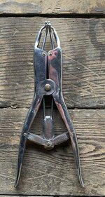
The tool is called an Elastrator. Widely used in the farming industry and numerous examples available on eBait! It was used to expand rubber components (EDIT: to apply a very small rubber ring on male farm animals to make a male into an it), allowing installation of wiring, etc. It works great with rubber grommets, etc. too.

a07e571ea20861b144edbb7c0f99897b16ed5c25_2_267x500.jpg
Elastorator3856×1600 364 KB

Elastorator
f0d9cb176c81076e6c8fd042092343432e4fb765_2_394x500.jpg
Elastrator11261×1600 348 KB

Elastrator - Expanded

Once the component (grommet, etc.) in fitted over the four prongs gently squeeze the handles which expands the prongs/grommet.
If I were to attempt to install a new Bulkhead Harness Grommet (C30670) I would first soften up the rubber by use of hot water. Next I’d apply a generous amount of lubricant (KY jelly) to the multi-pin wiring connector. When the grommet rubber is softened install on the Elastrator. Gently, very gently begin spreading the opening, just enough to force the grommet over the side of the connector. From there it’s just a matter of keep heating (in water) the grommet and continuing to slide it over the connector.
Hope this give some insight on how it MAY be accomplished but, as I mentioned, I’ve never replaced one. The main consideration would be keeping the rubber pliable by heating in water (boiling). Just proceed R E A L S L O W…
 
OP
C

Craig Balzer

Well-known member
Joined
Sep 21, 2005
Messages
867
Location
Colorado Springs
Somehow I managed to miss a major wrestling match I went through in Jan/Feb (I thought my postings above were a little light right after the New Year). Here is my log of effort directly after New Year's:

11JAN22: The Repair Operation’s Manual is extremely helpful in many respects and provides step-by-step procedures for 99.7% of things . . . right up until you bump into the dreaded verb “withdraw” the <item>

I am stripping the front of the block in preparation for extraction of the crankshaft and pistons: I have removed the timing cover, all timing chain dampers, timing chain tensioner, the cam gears/cams.

Next step: “withdraw” spacer and crankshaft sprocket". Yeah – – right.
How the ****** hell do you do that?? I even removed the 4x bolts securing the oil pump (see second photo) and gingerly used a dead blow hammer in an effort to use the oil pump to persuade the sprocket off the shaft. No Joy.


67e26b66aaa561bf165fadc2e691ef2d4d926167_2_500x500.jpg
11 - Oil Pump in Situ with Timing Chain1920×1920 414 KB

8c4417aa04924637d2aca0776e4217a0266a37f9_2_500x500.jpg
12 - Close oy of Oil Pump in Situ1920×1920 603 KB

000e08246b3a60f7df0ae507cd7a16816da3ea64_2_500x500.jpg
13 - Slot for Woodruff Key1920×1920 197 KB

This is a pretty ****** shot – I didn’t realize the camera pulled focus behind the spacer that is bane of my current existence; it was supposed to show the slot for an already-removed Woodruff key. But it does show the bevel on the spacer precluding use of a gear puller – nothing to grab on to.

I believe once the dreaded spacer is removed that the sprocket will follow. Or is that another “withdraw” action??

Reminder - the pistons and rings and crankshaft are frozen and I am unable to rotate that assembly
TIA
Craig
 
Last edited:
OP
C

Craig Balzer

Well-known member
Joined
Sep 21, 2005
Messages
867
Location
Colorado Springs
12JAN22 - Just came in from hobby shop. The spacer slid off the snout of the crankshaft as if I had installed it yesterday – I credit PB Blaster.

I tried the chisel trick on the sprocket – didn’t budge.
I tried a pry bars and various sizes of screwdrivers trying to walk the sprocket forward. No Joy.
Part of the challenge in removing the sprocket is a ridge of aluminum on the timing chain cover around the lower half of the sprocket (a guide of sorts to keep the chain from jumping track) – it is just visible in the photo so I can only put pressure on the top half of the sprocket.
So far I have been successful in getting only a 1/16" gap between the rear face of the sprocket and the forward face of the timing chain cover,


8c4417aa04924637d2aca0776e4217a0266a37f9_2_500x500.jpg
12 - Close oy of Oil Pump in Situ1920×1920 603 KB

It is soaking in PB Blaster but I am not expecting a significant change tomorrow .
It is ~on~ there.
 
OP
C

Craig Balzer

Well-known member
Joined
Sep 21, 2005
Messages
867
Location
Colorado Springs
12JAN22 -- I set aside my efforts to extract the sprocket and looked at:

Today I cleaned up and closely examined the Timing Chain Cover – among other actions.
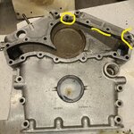
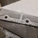
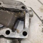
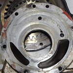
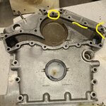
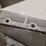
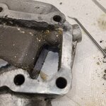
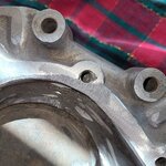
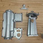
So this cover is really in very good shape – EXCEPT – for 2-3 places. Overview and close up photos follow (check captions as usual).
QUESTION
  1. Clean it up a little better and install it - most of the corrosion is on the inside of the rail
  2. Have the 2-3 locations that are corroded welded up (aluminum) and machined (who does that? Coventry West?). I highlighted the worst of them – if the answer is weld/repair, there are some smaller issues to be addressed
  3. Purchase new (or used in better condition) – Barratt says “Not available online” - Hmmm, is that Jag-speak for ****** expensive?

fbb7dece3627b145ff9a6c5460ba5e1df91f6cdf_2_500x500.jpg
1- Timing Cover - Overview1920×1920 749 KB


3c114df920870917ec1c6007d62018b73f6c20ce_2_500x500.jpg
Inked1- Timing Cover - Overview Marked Up1920×1920 749 KB


645b97803936e39ff3b23abda292a2aaf656da1b_2_500x500.jpg
4 - Timing Cover - Center1920×1920 630 KB


7b9c10abc64ab1abef47bc2724dec65759414c48_2_500x500.jpg
6 - Timing Cover - Upper Inside Right1920×1920 478 KB


a215eef5e627eb6024dd4df927ffca1c10c4eaac_2_500x500.jpg
7 - Timing Cover - Upper Right1920×1920 276 KB
 
OP
C

Craig Balzer

Well-known member
Joined
Sep 21, 2005
Messages
867
Location
Colorado Springs
17JAN22 - With regard to removing the crankshaft sprocket, I previously said this to my retired Jaguar-Mechanic friend Paul:

71768_2.jpg Craig_Balzer:
OK Obi Wan.
I did spend the better part of 2 hours working on it today.
May need another 2 tomorrow.
Well - it’s not what ya know, but who ya know. Paul made yet another trip from NE Denver to NE C Springs and brought a fellow gear-head along who wanted to check out the Jag and my shop. Paul also brought brought a slide hammer thingie.

Now all the slide hammers I have seen – both of them – had a threaded tip that screwed into a hole drilled in the center of a dent in a body panel which was then slide-hammered outward, mostly removing the dent. Paul’s slide hammer had three small fingers identical to a gear puller. The fingers weren’t long enough to allow all 3 to engage the pesky sprocket; the crankshaft snout was too long – he fussed for about 10 seconds to get good purchase of 2 of the fingers.

It happened too fast to count the number of strokes Paul applied to the slide, but my best guess is the sprocket was off the snout in less time than it took to finesse the fingers into place. The oil pump housing slid off the snout with no fanfare whatsoever.
I can now – finally – move forward in extracting the piston/sleeve assemblies and ultimately the crankshaft. Paul – you area Godsend. thanks so much. I treated Paul and his buddy to lunch.
 
OP
C

Craig Balzer

Well-known member
Joined
Sep 21, 2005
Messages
867
Location
Colorado Springs
18JAN22 - It was only a matter of time before I bumped into an unexpected expensive “find”. I was prepared to replace all 12 pistons and sleeves so that eventuality wasn’t really a surprise.

Today I dissected the oil pump – as mentioned above it slid off the crankshaft snout easily. Opening it was very straight forward – only needed to unbolt half a dozen 7/16" bolts and 4x 1/2". That’s where the fun ended.

I am not a mechanic but even I can recognize scratches that catch a thumb nail and gaps that are mostly out of spec. Please tell me some of this is salvageable but I suspect a $2,100 new high-capacity oil pressure oil pump is in my future. This proved to be the case.

The sad evidence follows (details in captions):

Nothing scary here:
64bc1aebf1c18b29ad8587c5a5eb3f6d880a56e3_2_500x500.jpg
1 - Overview of Oil Pump1920×1920 506 KB

These scratches on the under side of the cover easily catch my thumb nail
b5394fd1b08464c19c23516b7330d83f9a7999d0_2_500x500.jpg
2 - Underside of Oil Pump Cover - Thumb Nail Scrathces1920×1920 578 KB

Two gears in situ – more scratches that catch thumb nail
7cc084866dff1640c5e669a0e43c20d0d52a4e0e_2_500x500.jpg
3 - Two Gears and A Crescent - Thumbnail DOES grab on wear marks1920×1920 567 KB


Prolly don’t need a close up but the scratches/gouges are quite evident
81023c2b76a86b949e0513437015fd8e5b0efad9_2_500x500.jpg
4 - Two Gears and A Crescent - Close Up1920×1920 333 KB

Some measurements - the top note is for between the large gear and outer edge of the casing. The photo shows the gap between the small gear and crescent

df5238d6eb5865e833756576899a1cc218b3906b_2_500x500.jpg
6 - Measurements - gap between Inner Gear and Creasent1920×1920 255 KB


Finally some good news-- but not good enough to over balance the bad news
e7aaf1aa9e3d9d9449056ee81f71f164aaa492f7_2_500x500.jpg
7 - End Gap - This is Good1920×1920 241 KB


So – my budget just took a hit. This Jaguar stuff is not for the weak of heart or thin of wallet
 
Last edited:
OP
C

Craig Balzer

Well-known member
Joined
Sep 21, 2005
Messages
867
Location
Colorado Springs
24JAN22 - I turned my attention back to removing the crankshaft, pistons and liners.

The crankshaft in my original engine is not coming free nearly as easily as the one I extracted from the spare short block I purchased. (and used as a practice procedure). While the spare crank came out easy enough, at least three and perhaps 4 - 5 pistons are trash. I’m not sure about the sleeves.

The process to remove the crankshaft was familiar and started with numbering each piston’s bearing saddle 1 thru 12 from the front of the engine block (I coulda used the 1A and 3B designations formulated by Jaguar but I confess I have a hard time remembering which is the A bank and which the B. Then, looking at the block upside down I know I would get it backward). Then I extracted the crankshaft bearing housing. After I remembered to remove all 6 of the nuts on the studs (the two small ones on the inside of the fitting were well hidden and easily forgotten) it slipped out with a small bit of tapping with a brass drift and dead-blow hammer.

6cd54da1f387599bd1d24cc5d98fa46a2dc51efa_2_500x500.jpg
1 - Removing the Crankshaft Bearing Housing1920×1920 371 KB


While the pistons looked absolutely terrible on the crowns, once I got them out, they looked very clean and nearly new. See below. I didn’t take any shots of the underside of the crowns but they were virtually pristine.

1eab3ca07f0e16c540b243908d9fa48440db78d8_2_500x500.jpg
2 - After 2 Hours, removed 3 Pistons and the Crankshaft Bearing Housing1920×1920 407 KB


The efforts of day two was a mixture or success and failure. The success was the relatively easy extraction of 3 more piston bringing the total to 6. Failure: The remaining 6 pistons fall into three categories and are clustered together: the center 4 on one bank and the center two on the other bank. These were the pistons that had the biggest accumulation of crud on them.

Category 1: two pistons (# 4 and #10) whose position make access to the inside of the two ConRod nuts impossible.
76cf4eb59f4c6c87f7a9430de3b9204d7265ab45_2_500x500.jpg
5 - The rod labeled 4 also has ConRod bolts that are impossible to access1920×1920 372 KB


17ad3c8c0c4f4b157de3a0dd0b7589a6152f27a2_2_500x500.jpg
6 - The rod labeled 10 also has ConRod bolts that are impossible to access -- appears to be in the same position as piston 41920×1920 490 KB


Category 2: two pistons (number 5 and 7) whose position make access to the outside of the two ConRod nuts impossible (really the same problem as above, just that the ConRod nut is “pinned” to a different wall of the block.
These four pistons will likely be straight forward to be extracted IF I can resolve the issues surrounding the two pistons in category 3 (see next). I am assuming that once (if) I can extract the pistons in category 3, I’ll be able to rotate the crank and gain access to the last 4x ConRod nuts. But I’m getting ahead of myself.
f5176e8916f2619711febe7137694cbb7d819d52_2_500x500.jpg
4 - These four are not cooperating - the ones labeled 5 and 7 ConRod bolts that are impossible to access - the opther 2 are not budging1920×1920 434 KB


Category 3: two pistons that are defying all my efforts to extract. They are 6 and 8 and appear in the above photo.
Piston 6 shows the best chance of finally being extracted. The saddle is removed as are both halves of the bearing. The ConRod pivots on the Gideon Pin but not by much. This piston protrudes 0.2760” out of its sleeve. See last photo.

I’m not sure if the resistance is from the rings on the piston against the sleeve or the angle of the ConRod to the bottom of the piston not providing a good angle of attack for my brass drift and hammer. At least when I apply the brass drift to the ConRods and whack it – is has a hollow sound.
QUESTION: any ideas as to how to proceed? Patience and more thumping? (My lower back and shoulders are hurting after) Heat? if so, where is the heat applied? today’s efforts

Piston 8 is shown with a better view on the next photo:
029f7128b26bb550198ba3b5e01c1154100a8fcf_2_500x500.jpg
7 - the poston to the left is locked solid - no movement whatsoever. Black streak very evident1920×1920 404 KB


You can see that my thumping has punched out the one ConRod bolt. A close examination also shows half the bearing is still in place. This piston is 2.7240” deep in the sleeve. This piston is locked in the sleeve solidly – when I apply the brass drift to the ConRods and whack it – is has a solid sound, as if it a part of the block.

So – when all was said and done, this is the state of affairs at the end of day 2 of the crankshaft extraction:
e767c307442752209259f123c9bfe27c5a3e1537_2_500x500.jpg
8 - Progress at the end of day 2. Six pistons extracted, two refusing to budge, and four with inaccessible ConRod bolts ANNOTATED1920×1920 404 KB
 
OP
C

Craig Balzer

Well-known member
Joined
Sep 21, 2005
Messages
867
Location
Colorado Springs
So, on 31JAN22) took my block to a machinist who was able to extract 2 of the pistons in 24 hours. He is still working on the other 4 as well as repairing the one stud hole that I damaged. Also he is hot tanking the block.
I also took my Timing Chain Cover to a welder who specializes in aluminum.

Then Colorado got hit with an arctic blast that dumped a bunch of snow and provided daytime high’s in the teens and 20’s – over night temps as cold as -15°F. The better news is that the chromer I opted to use made their next annual trip to an auto show in Colorado bringing my newer chromed pieces with them.
edf51e9b42434025bce9cadba57a65f6aa0f41f4_2_500x500.jpg
1 - Returned Chrome Pieces - Overview I1920×1920 243 KB

a5de9124ea3c0e6472dd7e26a3b089d26d8d6550_2_500x500.jpg
1A - Returned Chrome Pieces - Overview II1920×1920 370 KB


I rejected 5 pieces and they agreed to re-chome them:
  • the left eyebrow was scratched during storage/transport
  • the center rear bumper was scratched during storage/transport
  • several dimples in the top windshield chrome strip were missed prior to chroming
  • the chromers assumed a face of the L/R A-Pillar dress pieces were covered by upholstery
They removed the push buttons from the exterior door handles for chroming. Looks like they ground off the attaching bracket from one of them.


67b9b1975ba1e97c29722695f5ea01c1afb9ddf1_2_500x500.jpg
3 - Returned Chrome Pieces - Door Handles and push buttons1920×1920 186 KB


The left tumbler housing is pretty beat up. I have found replacements and now have both tumbler housing waiting ot be fitted
b6a329217fdd99184bdfe104addc65706b22c300_2_500x500.jpg
4 - Returned Chrome Pieces - Close-up for tumbler casings1920×1920 311 KB


Some more happy snaps

2e0692673d230938aeda76b4a5e5689925b94048_2_500x500.jpg
8 - Returned Chrome Pieces - Long Trim pieces - side door spears, long and short door casing trim, window1920×1920 275 KB

6dd14709692c2f3aa1782e0e17fe02cca6e2a33d_2_500x500.jpg
5 - Returned Chrome Pieces - Interior Door Handles, Window Winder Escrutcheons1920×1920 428 KB
 
OP
C

Craig Balzer

Well-known member
Joined
Sep 21, 2005
Messages
867
Location
Colorado Springs
I had plans for wrenching today (08FEB220 in my hobby shop but 2 calls derailed those plans – in a good way
Call 1 – the aluminum welding repairs were done on the water pump cavity of the timing chain cover.
As a reminder, this is what needed attention.
BEFORE

3c114df920870917ec1c6007d62018b73f6c20ce_2_500x500.jpg
Inked1- Timing Cover - Overview Marked Up1920×1920 749 KB


645b97803936e39ff3b23abda292a2aaf656da1b_2_500x500.jpg
4 - Timing Cover - Center1920×1920 630 KB


7b9c10abc64ab1abef47bc2724dec65759414c48_2_500x500.jpg
6 - Timing Cover - Upper Inside Right1920×1920 478 KB


a215eef5e627eb6024dd4df927ffca1c10c4eaac_2_500x500.jpg
7 - Timing Cover - Upper Right1920×1920 276 KB

AFTER

0400f3eb050ba04ebeee27423d1ae28050717f20_2_500x500.jpg
5 - Overview1920×1920 542 KB


e1eb0c697a31eb76bb490116396da02ba9bc86c7_2_500x500.jpg
6 - Upper Left Bolt Hole1920×1920 444 KB


1344c60ff893699db8c9ddc67d5ca88bff7ee081_2_500x500.jpg
7 - Straight Away Repair1920×1920 451 KB


7e4c3b229313c144fbe1da7007f9e372f21d63b1_2_500x500.jpg
8 - Upper right bolt hole repair1920×1920 453 KB

Next – Call 2
 
OP
C

Craig Balzer

Well-known member
Joined
Sep 21, 2005
Messages
867
Location
Colorado Springs
The second call was from the machine shop where I took my block cuz
  1. Hot Tank
  2. Six Stuck Pistons/Sleeves
  3. Buggered stud hole
The Hot Tanking was straight forward – but I was expecting a cleaner outcome. I’ll be spending some time scrubbing the block – inside and out.

Repairing the stud was also a walk in the park for a machinist.

Now – unsticking the pistons/sleeves was a horse of an entirely different color. One piston/sleeve came out with a significant struggle and he had to use a band saw to slice the sleeve in two to extract the piston. I need to reuse the connecting rods as the are NLA. With the eBay-purchased short bock I have another 24 to choose from.

Another 2 of the 6 pistons/sleeves required some creative machinist-ology. Martin needed to build what was essentially a four-foot long slide hammer. I neglected to ask the weight of the slide.

Martin needed to make two holes 180° apart in the top of the sleeve so the “hooks” he added to the slide had a place to gain purchase. Two of the sleeves were so stuck that the force of the slide broke out a somewhat hemispherical chunk of material from the top of the sleeve requiring a new pair of holes to be made. It is no wonder I was TOTALLY unsuccessful in my combined efforts to turn the crank using the crankshaft bolt in the snout.

A close look at this first photo shows the repairs stud hole - 3rd from the right on the leading edge of the block (a darker hole (steel) than the others in the aluminum block):\
– \/

e19393256289cadbf4a2b0c75913864ca82191f5_2_500x500.jpg
Passenger Side1920×1920 456 KB

e94a6d324a5e0d719fc2ab96fe676abc5da7d9a3_2_500x500.jpg
Driver&#39;s side1920×1920 439 KB

37ab45f3d5a51496eea78766a9c6a8bc18c3d7cf_2_500x500.jpg
Driver&#39;s Side from Above II1920×1920 445 KB

004bcfce51f9b569c0f03d778b062019ef935ee6_2_500x500.jpg
Custom Made Tool to Slie Hammer (1)1920×1920 458 KB

/\ The big green end was machined to fix precisely into the sleeve once the piston was extracted or pushed down into the hole. The slide part of the hammer was at least 3.5’ long. It turns out someone somewhere along the way used an adhesive to glue the sleeves into the block. No bueno. They are held in place when the head is torqued onto the block
The machinist originally estimated $700 - $100 per stuck piston and then $50 to fix the buggered hole and $50 for hot tanking.
Due to the extreme efforts to remove the pistons/sleeves and having to fabricate/machine the special slide hammer, it came to $1,000
 
Last edited:
OP
C

Craig Balzer

Well-known member
Joined
Sep 21, 2005
Messages
867
Location
Colorado Springs
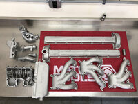
I don't recall if I already posted these photos, but here are happy snaps of some spare parts I had vapor blasted

20191016_114441.jpg
 

Attachments

  • 20191016_114459.jpg
    20191016_114459.jpg
    430.4 KB · Views: 5
  • 20191016_114707.jpg
    20191016_114707.jpg
    487.3 KB · Views: 4
  • unnamed.jpg
    unnamed.jpg
    383.8 KB · Views: 4
OP
C

Craig Balzer

Well-known member
Joined
Sep 21, 2005
Messages
867
Location
Colorado Springs
Vapor honing is such a cool process, its crazy how well it cleans parts up
I agree totally.
But a lot of people don't realize ya gotta blast each piece twice. The water in vapor blasting doesn't have the energy/oomph to remove paint/rust/powder coating (the water acts like a buffer). So ya gotta media blast it to clean it, them vapor blast for the texture.
 

fouckhest

Well-known member
Joined
Jul 24, 2013
Messages
1,862
Location
Greer, SC
I agree totally.
But a lot of people don't realize ya gotta blast each piece twice. The water in vapor blasting doesn't have the energy/oomph to remove paint/rust/powder coating (the water acts like a buffer). So ya gotta media blast it to clean it, them vapor blast for the texture.

I honestly did not know that....I've seen some cool builds/restorations using the process and the end results are great for an OEM+ look. Between VH and Cadmium plating, restorations are able to be so well done reasonably these days.
 
OP
C

Craig Balzer

Well-known member
Joined
Sep 21, 2005
Messages
867
Location
Colorado Springs
Finally got off my **** and back in my Hobby Shop. On top of arthritis and gout, I threw out my back by – get ready – standing upright after bending over engine bay of my 62 Thunderbird for nearly three minutes. Ouch. Damn – how pathetic. Another week on the couch.

I did use my “down” time to ship out some parts:
  • 40 pounds of bits to Van Nuys Plating for cadmium plating
  • all the gauges to West Valley for rebuilding/refurbishment except for . . .
  • the clock to a Jaguar forum member who is expert
  • dropped off my 3 header tanks to a radiator shop to have the best of the lot rebuilt
  • took my 65 Riviera to a shop for some upholstery work
In between of all of that, when my knee, ankle, and back worked simultaneously, I started laying the wiring harnesses.
  • threaded the bulkhead harness around the internal dashboard structure
  • threaded the left side harness through body structures from the trunk to the steering wheel
  • threaded the right side harness through body structures from the trunk to the glove box
  • started connecting them together
I got the passenger side bulkhead harness clamped in place

575fda376ffa23c7e7fa5226cffde7ae9891191c_2_500x500.jpg
PASSEN~21920×1920 279 KB


BELOW: the purple wire with white trace (at about 11 o’clock in the photo) took me two hours to install. It is the wire for the plunger on the a-pillar shut face for the map light. Just behind the bracket for the glove box at 9 o’clock is a body grommet the wire threads through – the plunger is just above the door check strap. The distance between the two is ~4-5 inches and involves the wire making a 90° turn to join with the plunger. To use the only aperture in the body structure would have involved having two more wrists on my left arm if it were the size of a 9 year old girl.

d6e5e49ab7182d1dbc642c664b2e60a0c52dc76d_2_500x500.jpg
Passenger Side - Join of Bulkhead Harness with right Side Harness1920×1920 343 KB


=====

I also connected the bulkhead harness to the driver’s side harness . . .

1dc5899d00b9df8185bd6cadfe25d29384b39d69_2_500x500.jpg
DRIVER~21920×1920 315 KB

. . . and discovered a bullet terminal missing off the orange wire. I reckon I’ll snip of the existing terminal and join the orange with a basic **** connector. I have the tool to snug the terminal to the wire, but don’t have a spare bullet connector; and the ones on the old harnesses have been crimped.


Tomorrow, I continue securing the bulkhead harness to the dashboard structure in the middle of the car and progress to securing the harness to the structure behind where the tacho and speedo will reside.
 
OP
C

Craig Balzer

Well-known member
Joined
Sep 21, 2005
Messages
867
Location
Colorado Springs
Attacked several areas on my Jag on 11MAY22

3 - I nearly finished installing the bulkhead harness.
d9f0bfcc36b8e41e2d9c43508153784774e8350c_2_500x500.jpg
Overview of progress at end of 11MAY22--1920×1920 418 KB

It took 2-3 hours to get this far. I had a few false starts

I ended up installing the harness clamp that is centered on the glove box space 3 or 4 times. I needed to uninstall several times to get enough slack in the harness to install other clamps. For any other Series III-ers installing a new harnesses - I needed to change tge orientation of the clamp to the left of the glove box opening. The way I initially installed the clamp (on the underside of the center panel) pulled harness downward – the clamp needed to pull the harness upward. This to clear room to install the cardboard-y ventilation hoses

The other backward step was mixing up attaching orientation the smaller limbs of the harness directly behind the steering wheel.

1b2f8246b222637d13b50519569c8c231f8e4622_2_500x500.jpg
Driver Side Bulkhead Harness in place and labeled1920×1920 489 KB

Both these clamps are clearly visible and didn’t require contortions to bolt down. It was simply irritating to have to swamp over this two lengths of the harness.


What I should have months ago took me a coupla hours today. I labeled all the terminals on the harness – not just 20-30% of them figuring the unlabeled ones would be obvious. Still need to address the wiring in the center of the dash. These should go pretty quickly cuz groups of attached by bunch to the fuse boxes. Yeah – right; we’ll see how that goes.

On the passenger side, just need to connect two cans/flashers/somethings to the footwell and attach a total of 5 wires.

46b3f0fbcb3bd237086be4a97c2f90dadb25730a_2_500x500.jpg
Passenger side justs needs two cans attached to the unpainted ve1920×1920 445 KB
 
OP
C

Craig Balzer

Well-known member
Joined
Sep 21, 2005
Messages
867
Location
Colorado Springs
Th afternoon of 12MAY22, I just about completed all the connections in the center of the dashboard – at least from the bulkhead harness. I installed the hardura (?) element which is held in place by the top two fuse blocks; also installed the other two fuse blocks.

I was gonna start labeling all the wires when it dawned on me that the old harness was laying right there and was a perfect template. Since I was installing 4x new fuse blocks, even the old fuse blocks were intact on the old harness. So – I laid the old harness across the scuttle and followed started attaching new wires.

885d01d570a76c2940087c45eaf901e199682cac_2_500x500.jpg
1 - Its easier to use the old harness as a guide1920×1920 521 KB

Just about got it – just need to chase down a few issues.

2d9c15b42a50fb46f0356a9c251d1e924dd82ea4_2_500x500.jpg
2 - Just about got the Center Panel rewired1920×1920 556 KB


The first issue I need to resolve in the new harness has 5 relatively short purple wires implying they all connect to lower left fuse block

d5ef849670a81bca9a9a6091a1454d7432818dfa_2_500x500.jpg
3 - New harness has 5 purple wires . . .1920×1920 307 KB


The old harness has the 5 purple wires but only 4 go to the fuse box; one is much longer and has black ring on it. Other wires have this colored ring on it so I know it is significant. Just haven’t figured out that significance yet.

491cd4a108d0b0e3b86e847ab82e42397babbd44_2_500x500.jpg
4 - Old harness has 5 purples but 1 is long and has black ring1920×1920 391 KB


The second issue is less daunting and Jaguar forum members who have replaced their harness may be able to answer it. The new harness has two long brown wires leading to one fuse box

37b54e1216fe30545b972b2291bb91d6c518f801_2_500x500.jpg
5 New harness has 2 long brown wires . . .1920×1920 350 KB


Whereas the old harness has two equally long pair of wires leading to the same fuse box, but are whitish or a grey color. Are they the same pair if wires? Logic says yes, but . . .

c51b521c7c37bac0e2f62faffb9ee21329347970_2_500x500.jpg
6 - Old harness has the cloth wrapped whitish wires1920×1920 346 KB


Also cleaned up some wires attaching to various cans and flashers in the passenger footwell;

daab2a7027b5c395f1a789cb84a21a3b5c12a4e8_2_500x500.jpg
7 - Finished up attaching 2 flashers in passenger footwell1920×1920 214 KB


And I have 1 oops to trace down. This red wire is attached to the same fuse box with the other red wires on the upper right fuse box. I didn’t note where this red wire with a small bulb on the end goes. After 48 hours of exchanging messages with Jaguar forum members (and checking my photo archives), I discovered this wire/bulb drop down from the fuse box, curves outboard and behind the glove box to plug into the choke becoming the choke indicator lamp. It is NOT on any of the Jaguar or after market wiring diagrams -- of whohc I have several.

21d4dcace3195839b5ce96fd51268586f9467190_2_500x500.jpg
20220512_1605471920×1920 273 KB
 

Jayman17

Well-known member
Joined
Feb 6, 2017
Messages
3,812
Location
Seattle, Wa
Wow that looks incredibly confusing! Sending you best wishes on getting that straightened out and installed correctly.

Jay
 
OP
C

Craig Balzer

Well-known member
Joined
Sep 21, 2005
Messages
867
Location
Colorado Springs
Thanks Jay -- I am not moving quickly and I double check (and sometimes triple check) the connections on the old harness before moving on to the next wire. My goal is for the car to start on the first crank and all gauges, accessories and things to work right out of the gate.

We'll see
 
Last edited:
To avoid these ads, REGISTER NOW!
Top Bottom