To avoid these ads, REGISTER NOW!

Creating a simple flip flop circuit

Matt Matt

Well-known member
Joined
May 11, 2017
Messages
523
Location
Ontario
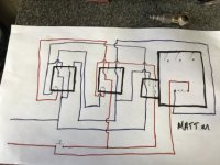
I have a dust collection system project coming up. (I hope, I don’t have to get my technologist on board as it’s kind of a personal project .) I want to be able to start/stop my dust collection system using 12-24 V low voltage momentary buttons (similar to doorbell). Three wire control system will hold a circuit, if you add a DPDT, this should hold it. Adding another DPDT should kill it for power failure and/or shut down. A main Contactor (size 2)should be able to carry the 5 hp 1P dust collector. I’m fine with the electrical part. And the code. I’m just wondering if anybody has a simple flip-flop wiring circuit diagram using two ice cubes for controls? I’m definitely open for questioning... but I’d like to try to keep this is a control circuit! I do want to add any E stop, but that is pretty simple and not my question. Maybe engineers or technologists or electrical control wiring guys. Sorry if this is a brainteaser.

I’ll try to put to post my rough wiring schematic tomorrow for critique.

I want to use a Allen Bradley momentary button to start and stop with each press, the dust collection system. In power loss, I want the system to remain off in power recovery! I pretty much want to use HVAC Control (18g,300v)wire for the control circuit.
 
Last edited:
To avoid these ads, REGISTER NOW!

rockwithjason

Well-known member
Joined
Jan 8, 2006
Messages
2,633
Location
Las Vegas
why are you not using simple 3 wire control circuits? you can do everything you want and you don't have to reinvent the wheel.
this video shows for a three phase motor but it works with a single phase motor too
 

mm08822

Well-known member
Joined
Jan 13, 2012
Messages
6,048
Location
NJ
why are you not using simple 3 wire control circuits? you can do everything you want and you don't have to reinvent the wheel.
this video shows for a three phase motor but it works with a single phase motor too

My thoughts too, keep it simple.
However, doorbell buttons and bell wire are super cheap.
These's more than one way to accomplish it.
 
OP
M

Matt Matt

Well-known member
Joined
May 11, 2017
Messages
523
Location
Ontario
Well it’s not so simple. I think it’ll do what I’m trying achieve.
 

Attachments

  • 4B861290-0D56-4B54-BBE8-A7B8A0618E54.jpg
    4B861290-0D56-4B54-BBE8-A7B8A0618E54.jpg
    19.1 KB · Views: 50

Mr. T

Well-known member
Joined
Sep 4, 2013
Messages
636
Location
Central PA
If you aren't afraid of a little programming a micro810 is dirt cheap and adds some flexibility. Price might be a wash though.
 

walta

Well-known member
Joined
Jan 13, 2017
Messages
2,313
Location
Dutzow Missouri
If you have a 24 volt magnetic starter on the collector it should not be difficult to wire a pair of 3 wire control stations to it.

It is very likely your Allen Bradley buttons are not DPDT most of the starts buttons are NO and the stops are NC

Walta
 

ahazi

Well-known member
Joined
Jan 4, 2015
Messages
55
Location
Los Angeles, CA
Look at the links that I posted (actually very clever design). It is very simple and will do exactly what you need/asked for, namely on/off control by a single N.O. (normally open) push button switch.

Let me know if you need more help.

Ariel
 
OP
M

Matt Matt

Well-known member
Joined
May 11, 2017
Messages
523
Location
Ontario
The reason why I want a low-voltage control circuit is;
I actually want to power this off the A battery. The system is a little more complex then I’m getting into with you guys. It is going to charge a small air compressor and the blast gates that will work pneumatically. I’m actually looking into getting momentary control relay circuit boards made. I just need to get a proof of concept first. The dust collection system may work off of a VFD to regulate CFM based on how many gates are open.... but now I’m getting ahead of myself.

My end goal is to have a simple dust collection system for idiots. One button on, one button off. One momentary stop that will reset the whole system at any part of the day, and e-stops in a few locations.

I’m about two or three days away from finishing building a silent air compressor that is going to do pneumatic part. I’ve been calling it my “the silent pipe bomb Air compressor”.

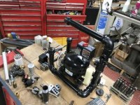
Maybe if anybody’s interested in the little air compressor I’ll start another thread. But as for now this is A 3 year Old refrigerator Freon compressor that I am repurposing for fun.
 

Attachments

  • 68304B5B-976C-447B-AF37-954FE3103FD4.jpg
    68304B5B-976C-447B-AF37-954FE3103FD4.jpg
    30.6 KB · Views: 35
Last edited:
To avoid these ads, REGISTER NOW!
OP
M

Matt Matt

Well-known member
Joined
May 11, 2017
Messages
523
Location
Ontario
Look at the links that I posted (actually very clever design). It is very simple and will do exactly what you need/asked for, namely on/off control by a single N.O. (normally open) push button switch.

Let me know if you need more help.

Ariel

Wow!
I really wish I found that link. One of their more complex circuits is exactly what I spent three hours trying to figure out. But it wasn’t exactly where you link me to. The link does give another link to my proof of concept. Thanks! I think number 14 or 15 is what I came up with.
http://www.emil.matei.ro/onof3.php
 
Last edited:

ddawg16

Well-known member
Joined
Jul 11, 2008
Messages
21,005
Location
S. California
A classic example of relay logic.....

And why PLC's were created.

If it was me, I'd be doing what MrT suggested and use a Micro810....and the software is free

Or, if you're not afraid of Python....a Raspberry Pi with a relay board.
 

ahazi

Well-known member
Joined
Jan 4, 2015
Messages
55
Location
Los Angeles, CA
Wow!
I really wish I found that link. One of their more complex circuits is exactly what I spent three hours trying to figure out. But it wasn’t exactly where you link me to. The link does give another link to my proof of concept. Thanks! I think number 14 or 15 is what I came up with.
http://www.emil.matei.ro/onof3.php

Here is another web link to essentially the same circuit:
Look down the page for "T flip-flop"
http://www.homofaciens.de/technics-base-circuits-relay_en.htm

Also a picture to how to build it if you are not into electronics and relays:
http://www.homofaciens.de/bilder/technik/relay_041.htm

I disagree with the PLC advocates for this function - if you want a simple, inexpensive and reliable way to achieve your goal this is a good way to go. I have worked on many logic circuits over the years and for certain things relays are a very good solution. You can find some very inexpensive sealed relays on eBay. Since the actual load is carried by a big relay "contactor" there is practically no wear on this little circuit. Also using simple inexpensive N.O. SPST push buttons (which you can run in parallel as opposed to SPDT or N.C push buttons) makes this a nice solution.

Good luck!

Ariel
 

ddawg16

Well-known member
Joined
Jul 11, 2008
Messages
21,005
Location
S. California
I disagree with the PLC advocates for this function - if you want a simple, inexpensive and reliable way to achieve your goal this is a good way to go. I have worked on many logic circuits over the years and for certain things relays are a very good solution. You can find some very inexpensive sealed relays on eBay. Since the actual load is carried by a big relay "contactor" there is practically no wear on this little circuit. Also using simple inexpensive N.O. SPST push buttons (which you can run in parallel as opposed to SPDT or N.C push buttons) makes this a nice solution.

Good luck!

Ariel

Good luck adding features like time delays or auto off. Yea, sure, you can do it with time delay relays.....but they cost more than the Micro.

A Micro820 has 7 relay outputs...8 120Vac inputs, 4 24Vdc inputs....and you can add more. Ethernet and serial ports....you can add an LCD display.

A perfect example of what you can do with it....automatically sense when a power tool is turned on....then automatically turn off after say 20 seconds when the tool stops.

If manually turned on, you can program it to turn off after say 10 min of no activity.

So many options....and you don't have to spend half the day running wires.

A typical AB relay will cost you $25 or more. It doesn't take long to spend as much if not more than the Micro810.
 

ahazi

Well-known member
Joined
Jan 4, 2015
Messages
55
Location
Los Angeles, CA
Good luck adding features like time delays or auto off. Yea, sure, you can do it with time delay relays.....but they cost more than the Micro.

A Micro820 has 7 relay outputs...8 120Vac inputs, 4 24Vdc inputs....and you can add more. Ethernet and serial ports....you can add an LCD display.

A perfect example of what you can do with it....automatically sense when a power tool is turned on....then automatically turn off after say 20 seconds when the tool stops.

If manually turned on, you can program it to turn off after say 10 min of no activity.

So many options....and you don't have to spend half the day running wires.

A typical AB relay will cost you $25 or more. It doesn't take long to spend as much if not more than the Micro810.

I agree that if you need more features using relays is not a wise or economical solution. But... for this function you don't need AB relays. You can get 10 ea. of 12 volt DPDT sealed relays for about $20. So this all depends on price sensitivity and if this is a one off project or something else.

I will look more into the Micro820 as a candidate for my own projects.

Ariel
 

matt_i

Well-known member
Joined
Mar 14, 2008
Messages
10,742
Location
SE Michigan
I'm having a hard time visualizing your wiring diagram. As others suggested the 3 wire control is classic, the starts (NO) all go in parallel and the stops (NO) all go in series.

I don't get the need for an Estop (other than you don't trust the VFD or you fear a welded-contact..but on 24vac...?), for a NEMA-2-only system its basically the same thing, just detented and a 2-wire system but must ultimately control a magnetic device (a redundant one or the same one). An Estop backing up a VFD obviously have their purpose in industrial settings but for a personal shop its a bit of extra expense.

I am building a simple circuit for starting and stopping my phase converter from a multi room building using 3 way and 4 way switches (which ultimately go to a coil as I need a dry contact ) Its not a mag device so would have implications in a power outage but I'm OK with it.

Apologies for the College Football Playoff logo in there..doodling on my wiring diagram :eyecrazy: There are also a set of indicator lights. The lights could be push-to-test but I decided against that feature for right now.


Sample control station.
 
Last edited:
To avoid these ads, REGISTER NOW!
Top Bottom