To avoid these ads, REGISTER NOW!

Critique my plan for constructing server rack rails

MattH

Member
Joined
Mar 10, 2023
Messages
19
I'm building rails for a server rack (19-inch rack) and would appreciate critique and feedback on my plan before I get too far into this process. I have almost no experience doing these types of things and would like to be saved from making stupid mistakes and wasting money and time. I've attached a picture of roughly what this rail will look like in a rack. The purpose of these rails is to provide vertical support for heavy electronic equipment (up to about 110lb but typically closer to 30lb). The equipment will also be fastened to the front mounting holes and therefore needs to be vertically-aligned correctly.

I'll be using 19.5" lengths of 2.5x1.5", 3/16" thick steel angle. I cut this from 20' lengths at the supplier. I haven't been able to find stainless steel or galvanized steel in the 2.5x1.5", 3/16" thick dimensions, so I have to use regular steel. The long leg can be longer than 2.5", but the short leg must be less than 1.75". It's critical that these rails be rust-free (and remain that way), so I'm planning to have the steel galvanized at a local galvanizer after performing all cutting operations on it. This will be used in an indoor, temperature-controlled environment.

The fasteners are M6 (0.236in OD). I saw that 6.3-6.6mm (0.248-0.260") clearance holes are typical. Additionally, the galvanizer told me the process typically adds between 3 and 10mil of thickness. Therefore, the hole diameter should be reduced between 6 and 20mil. If I use a 17/64" drill bit for the hole, the resulting hole diameter after galvanziation should be 0.246-0.260", which seems just about right.

Are my calculations for the pre-galvanization hole diameter reasonable? Is my overall procedure for creating rack rails like this sound? Or, are there better/easier ways?

I've tested the rack rail before galvanization (shown in the picture) and the fit and dimensions work well.

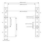
I do realize that the vertical load-bearing capability of these rails would be improved if I could have a 2nd set of screws directly above the first set. Unfortunately, that's not possible as this edge of the rail needs to be less than 1 rack unit (1.75"). The 2nd picture shows 19-inch rack dimensions. Still, I've tested this with some heavy equipment and it seems to be really solid.

I can go into more detail about the dimensions for the rail, including the vertical position of the holes, etc. but that part I think I got right, so I haven't included it.
 

Attachments

  • IMG_2592.JPG
    IMG_2592.JPG
    434.5 KB · Views: 38
  • 19_inch_rack_dimensions.png
    19_inch_rack_dimensions.png
    20.6 KB · Views: 43
To avoid these ads, REGISTER NOW!

nutjob

Well-known member
Joined
May 8, 2008
Messages
806
Location
NE, PA
Or, are there better/easier ways?

Yep, just purchase rack rails. 3/16" is way over kill and using angle iron may not allow some equipment to fully sit flat.
This is a common part from all the rack manufactures and I have installed hundreds years ago when servers did not have slides.

Kevin
 
OP
M

MattH

Member
Joined
Mar 10, 2023
Messages
19
I spent a bit of time looking, and wasn't able to find any commercial options that worked (more detail below). But, if you do know of a product that's suitable and reasonably priced, I would be thrilled to use that avoid all this work.

Some of the requirements for these rails are:

- Must fully support the weight of equipment up to about 110lbs, preferably more.
- Must not use the front or rear panel mounting holes. Therefore, it can only use the interior mounting holes (you can see these in the picture in my first post). The front/rear mounting holes are needed to fasten the rack ears of the equipment to rack.
- Must not take up more than 1U vertical space. This allows their use for 1U equipment. Basically, I need to be able to remove any individual instrument without needing to remove any other instrument.
- The rack rails are primarily geared toward Hewlett-Packard type-II cabinet test equipment. I've attached a picture of one of these sitting in the rack. The front rack ears are not fastened, but will be. These units take up an integer number of rack units. The total height is about 1/32" less than the allocated rack unit space. The body (behind the front bezel/frame) leaves about 0.06" on the top and 0.19" on the bottom, hence the space for a 3/16" rail. The body width is about 16.75". The width between interior mounting holes on my Navepoint rack is about 19.25". The rails need to be wide enough such that the instrument cannot fall through if it gets pushed to one side.

I'd previously been using 4POSTRAILSM Tripp-Lite rails. But, these were not nearly strong enough for heavy equipment. It's possible they met their 200lb spec, but probably only if the equipment edges extended out to near the sides. Even then, this claim is dubious based on what I saw. With the HP equipment I'm mostly dealing with and the racks I'm using, the rails produced significant bend for even moderate-weight units. As a result, I ended up doing funny things like adding cross supports to distribute the weight out to the edges and placing another rail upside-down just below another for heavy units (you can see all this in the second picture). In addition to violating a lot of the criteria above, this configuration made it hard to slide equipment in and out (the cross supports got in the way of this) and the rails were absurdly expensive for what they are. I only bought them because I got them for less than half the retail price.

I am aware that some equipment will not work with the rails I'm fabricating; particularly those that leave less vertical space. For those, I'll still use these Tripp-Lite rails, or maybe something else if they also don't work.

I am also aware that 3/16" is overkill, but it was hard to find 2.5x1.5 in other thicknesses.
 

Attachments

  • IMG_2593.JPG
    IMG_2593.JPG
    506 KB · Views: 32
  • IMG_2594.JPG
    IMG_2594.JPG
    515.9 KB · Views: 29

rlitman

Well-known member
Joined
Oct 18, 2010
Messages
24,598
Location
Long Island
Lotsa issues with your plan. First, the thickness of the bottom of the rail as stated above needs to be much thinner than that angle. Even 1/8" angle steel will interfere with your equipment spacing and give you major headaches getting everything to fit correctly.

Second, the rails must be attached to the front and rear cabinet rails and NOT to the side rails you bolted to. Installed like that, your equipment will hardly contact the last 1/2" of the flange, and your angles will be twisting downwards.

Third, real generic 4-post rack rails are cheaper than your time is worth to make them. I've scrapped so many of them over the years after running out of room to store extras. So, your best option is to befriend someone who works at a data center. Where are you located?
 
To avoid these ads, REGISTER NOW!
OP
M

MattH

Member
Joined
Mar 10, 2023
Messages
19
Lotsa issues with your plan. First, the thickness of the bottom of the rail as stated above needs to be much thinner than that angle. Even 1/8" angle steel will interfere with your equipment spacing and give you major headaches getting everything to fit correctly.

This is actually ok. Hopefully the dimensions I provided in my 2nd post clarify why this works. I have tested this and the fit works well.

Second, the rails must be attached to the front and rear cabinet rails and NOT to the side rails you bolted to. Installed like that, your equipment will hardly contact the last 1/2" of the flange, and your angles will be twisting downwards.

It's actually about 1.25" overlap on each side. I also don't like the fact that the instrument weight will produce a twisting action on the rails, but it seems to be ok. I placed some heavy equipment on the rails and it seems solid.

Third, real generic 4-post rack rails are cheaper than your time is worth to make them. I've scrapped so many of them over the years after running out of room to store extras. So, your best option is to befriend someone who works at a data center. Where are you located?

Again, I just haven't found any rails that meet my criteria. I'm in Oakland CA.

I've attached a picture showing the racks and rails originally designed for this equipment. Those rails have a nice design in that they clip into a little slot on the side, in addition to the screw fastening. This should reduce some of the twisting action. Unfortunately, those racks are way out of budget for me.
 

Attachments

  • hp_equipment_rack_2.jpg
    hp_equipment_rack_2.jpg
    453.3 KB · Views: 24

rlitman

Well-known member
Joined
Oct 18, 2010
Messages
24,598
Location
Long Island
...
- Must fully support the weight of equipment up to about 110lbs, preferably more.
- Must not use the front or rear panel mounting holes. Therefore, it can only use the interior mounting holes (you can see these in the picture in my first post). The front/rear mounting holes are needed to fasten the rack ears of the equipment to rack.
- Must not take up more than 1U vertical space. This allows their use for 1U equipment. Basically, I need to be able to remove any individual instrument without needing to remove any other instrument.
...
Maybe, no, and no.

110lbs is not a problem for heavier 2U rails made to support a UPS (it's a bit much to expect that much weight in less than 3U...), but you're not getting that strength in 1U sizing, and your 1U equipment doesn't weigh that much anyway. Being able to remove any single piece of equipment has nothing to do with using 1U rails. It just means that every piece of equipment must rest on it's own pair of rails that can be easily swapped out when you change equipment.

No, you really do want to use the front and rear panel mounting holes to hang your rails. Rails with threaded bolt holes will mount inboard of the cabinet vertical rails, with screws with centering washers to work with your square holes. Alternatively, some use cage nuts in the square holes and mount outboard. Regardless, you want rails that bolt on the uppermost and lowermost holes for your 2U equipment (or the middle of each U), with pass-through holes to allow your equipment to bolt through the pair of holes between those. Your equipment will bolt to EITHER the front OR the rear cabinet rails, but not both. Look at where the bolt holes are on that piece of equipment and you'll understand. Yes, that means that your equipment will be spaced forward of the cabinet rails by the heads of the bolts holding the horizontal rails in place, but that doesn't lessen how well it is supported.

Equipment that has sliding rear extensions to bolt to the rear rails of the cabinet is designed to be bolted to the vertical rails alone, and not sit on anything. I HATE that kind of stuff, but acknowledge that it does exist.

Also, keep in mind that those "interior mounting holes" may not be accessible when the cabinet is full (whereas the vertical rack rails are always accessible). Will this cabinet be adjacent to other cabinets? Does it have enclosed sides? Build this with the expectation of making it easiest to service later.

So if you expect to bolt your angle iron to them on every U turning the cabinet into a baker's rack, how do you expect to mount 2U equipment that will interfere with rails in every U? And if you fill the cabinet with 2U equipment with rails spaced at 2U intervals, don't think you can access those side holes to add another rail and fit 1U equipment in an open slot later on.
 

nutjob

Well-known member
Joined
May 8, 2008
Messages
806
Location
NE, PA
This is the pic of what we used, made by Winsted. This is 14 gauge, zinc plated. These mount on the inside like you want and have held some very heavy equipment no sag. Google around I'm sure you can find something that will work

Kevin

IMG_1328 (Large).JPG
 
OP
M

MattH

Member
Joined
Mar 10, 2023
Messages
19
110lbs is not a problem for heavier 2U rails made to support a UPS (it's a bit much to expect that much weight in less than 3U...), but you're not getting that strength in 1U sizing, and your 1U equipment doesn't weigh that much anyway. Being able to remove any single piece of equipment has nothing to do with using 1U rails. It just means that every piece of equipment must rest on it's own pair of rails that can be easily swapped out when you change equipment.

True, the 1U are not 110lbs and I could use different rails for those, opening up the possibility of using rails with a longer vertical edge (and a higher screw attachment point for reduced twisting). I did like the idea of having the same rail for all units, but if the current design is unsuitable for heavy units, I can use different rails for 1U units from those used for >1U.

No, you really do want to use the front and rear panel mounting holes to hang your rails. Rails with threaded bolt holes will mount inboard of the cabinet vertical rails, with screws with centering washers to work with your square holes. Alternatively, some use cage nuts in the square holes and mount outboard. Regardless, you want rails that bolt on the uppermost and lowermost holes for your 2U equipment (or the middle of each U), with pass-through holes to allow your equipment to bolt through the pair of holes between those. Your equipment will bolt to EITHER the front OR the rear cabinet rails, but not both. Look at where the bolt holes are on that piece of equipment and you'll understand. Yes, that means that your equipment will be spaced forward of the cabinet rails by the heads of the bolts holding the horizontal rails in place, but that doesn't lessen how well it is supported.

Yeah I think I follow you and that makes sense. I did a quick search and what I found was still quite expensive - much more expensive than the cost of fabricating something myself. If you have any product recommendations, please post them. Or just a picture of something so I can be sure I understand you. I'm happy to buy them used too, but a quick look on craigslist in my area didn't yield much and the prices weren't great either.

I am aware that my equipment only fastens to front or back (not both), but I use the rear mounting holes for other purposes: power outlets, and small, lightweight auxiliary equipment. I still want to leave those free for that.

Equipment that has sliding rear extensions to bolt to the rear rails of the cabinet is designed to be bolted to the vertical rails alone, and not sit on anything. I HATE that kind of stuff, but acknowledge that it does exist.

I'm not dealing with these.

Also, keep in mind that those "interior mounting holes" may not be accessible when the cabinet is full (whereas the vertical rack rails are always accessible). Will this cabinet be adjacent to other cabinets? Does it have enclosed sides? Build this with the expectation of making it easiest to service later.

So if you expect to bolt your angle iron to them on every U turning the cabinet into a baker's rack, how do you expect to mount 2U equipment that will interfere with rails in every U? And if you fill the cabinet with 2U equipment with rails spaced at 2U intervals, don't think you can access those side holes to add another rail and fit 1U equipment in an open slot later on.

I don't need the interior mounting holes to be accessible when the cabinet is full. I will only access the rail when the equipment it supports is removed.

I had no intention of filling every U with a rail. If I decide to change the equipment in a rack I will often need to pull out multiple units and change position of the rails - that's fine and I don't do that often. I also don't see any way around that. My equipment is not all the same number of rack units. But, I do frequently need to service equipment, which entails just removing it and then putting it back in when I'm done.

For >1U I could use something like 2x3 or 3x3 and place a mounting screw higher up, which should improve the twisting. I'd probably have 4 screw holes for this, 2 sets of 2 stacked vertically. That does increase the material cost and weight, but that's probably still ok.

I appreciate that people think my solution is unnecessary, but the only actual problem I see so far is the twisting action for heavy equipment. I've run some calculations to attempt to see whether this is actually an issue. I've attached a sketch showing the dimensions and forces. Assuming a 110lb instrument, half the weight will be on each rail, or 55lb. The rail width is 2.5" and the equipment contacts the rail from 1.25" to the end. So, 55lb is distributed over 1.25". We therefore assume the full 55lb weight is 1.875" from the corner of the rail. The fastener will exert the upward counteracting force, to prevent the rail moving vertically. The attachment point is the screw, so the instrument weight will produce a torque on the rail (the r vector is the one from the screw to where the weight is centered on the rail). I calculated this torque to be 103lb-in. The rack will need to exert a force on the vertical part of the rail to prevent the rail from rotating. This force should be somewhat distributed over the side between the screw and corner of the rail, but will probably be mostly concentrated at the corner of the rail. Anyway, if we assume the force only occurs at the corner that would be 118lb. In reality, the force will be somewhat distributed over the vertical edge and so the force at any given point will be less than this 118lb. The screw will need to counter that with a tensile force of equal magnitude and opposite direction to prevent the rail moving horizontally.

118lb seems totally fine for an M6 screw. This also seems ok for the force of the rail against the rack, but admittedly I don't really know (FYI the rack is 16 gauge steel). Of course, things get better if I make the vertical edge longer and mount the screw higher up. For instance, with a screw mounted 2.625" from the corner of the rail (middle hole in the 1U above), the forces on screw and rack drop to 39lb.
 

Attachments

  • IMG_2596.JPG
    IMG_2596.JPG
    478.3 KB · Views: 23
Last edited:
OP
M

MattH

Member
Joined
Mar 10, 2023
Messages
19
This is the pic of what we used, made by Winsted. This is 14 gauge, zinc plated. These mount on the inside like you want and have held some very heavy equipment no sag. Google around I'm sure you can find something that will work

These look nice, and are similar to what I've been looking for. The one issue with the Navepoint rack that I'm using is that those don't really look wide enough based on the equipment width and distance between interior mounting holes.

Those do look like they'd be subject to the same twisting as my solution, so if those hold well that's a good sign.
 
To avoid these ads, REGISTER NOW!
Top Bottom