To avoid these ads, REGISTER NOW!

Devilbiss 432 Teardown

hawkerxj

Well-known member
Joined
Jul 19, 2016
Messages
65
Location
Miramichi NB
Does anyone have a service manual for a Devilbiss 432. I picked one up used for a couple hundred with no motor, unknown shape and questionable tank. I would like to tear into it before I use it, make sure everything is in good shape. The tank pressure tested good to 350psi, and with a bit of sand paper the mag starter works again. I picked up a 5hp 4 pole for it, so just need to check out the pump. (Ahh maybe I should just plop it back on there and fire it up, it sounds like it should work when you roll it over)
 
To avoid these ads, REGISTER NOW!
OP
H

hawkerxj

Well-known member
Joined
Jul 19, 2016
Messages
65
Location
Miramichi NB
Thanks dreamer, that is great. You know, I had a copy of that all along but it was missing the last 2 pages with the torque values and bore specs. I'm certain I have already looked at that specific one also, but brushed it off as the same as the one I already had.
Check out the tank before and after blast and paint.
Hawker
 

Attachments

  • Air Reciever Before.jpg
    Air Reciever Before.jpg
    88.5 KB · Views: 98
  • Air Reciever After.jpg
    Air Reciever After.jpg
    60.7 KB · Views: 99
Last edited:
OP
H

hawkerxj

Well-known member
Joined
Jul 19, 2016
Messages
65
Location
Miramichi NB
I pulled all the valve to see if there were any broken spring or disc or anything. Not much drama, everything came apart ok and appears to be intact. I'll clean them all up and make sure. Would you guys recommend replacing the spring and discs, or just try lapping them? I tried leak testing with the cleaning solvent, a few were OK but most leaked out within 30 seconds. One of the LP cylinders may have an issue, but I'll get to that in a day or two.
 

Attachments

  • 20190126_224914.jpg
    20190126_224914.jpg
    132.3 KB · Views: 113
  • 20190126_231226.jpg
    20190126_231226.jpg
    120 KB · Views: 88

CBassB

Well-known member
Joined
Mar 10, 2018
Messages
61
Location
Canada
I've rebuilt a few of these after valve failures and it causes quite a bit of damage. I would personally replace the disks and springs. They should be fairly cheap. That said, it probably won't break tomorrow, so if you want to see it run all the pieces are there, just fire it up.

S
 
OP
H

hawkerxj

Well-known member
Joined
Jul 19, 2016
Messages
65
Location
Miramichi NB
So before I go and rebuild the valves, I want to finish the teardown and make sure there aren't any deal breaker problems. So I got one side(the bad side) of the cylinders off and its gonna need some work, I'm just not sure how much. The first picture is the LP cylinder, after removal, second is HP cylinder. The last picture is the LP cylinder after a bit of cleaning. So what are my options here? It seems like I can get the overhaul kit from Devilbiss with oversized 0.020 rings, do I need new pistons as well for proper skirt clearance? It seem aftermarket may have a 0.10 oversize rings option also. Also are there any tell tales sign to show if it has already been bored out. I don't currently have a bore gauge, but may soon buy/borrow one. Is there any chance I could hone it and it still be within the original ring size? The crank appears to be in good shape, but I haven't measured the journals yet. Any other things I should verify before spending the $600CAD on the overhaul kit. Or any better prices out the for the kits? Any advice is appreciated.
Thanks,
 

Attachments

  • 20190129_233339.jpg
    20190129_233339.jpg
    79.3 KB · Views: 81
  • 20190129_225907.jpg
    20190129_225907.jpg
    124.2 KB · Views: 80
  • 20190129_225823.jpg
    20190129_225823.jpg
    111.8 KB · Views: 84
  • 20190129_225814.jpg
    20190129_225814.jpg
    101.3 KB · Views: 89

MacMcMacmac

Well-known member
Joined
Oct 21, 2014
Messages
1,578
Location
canada
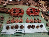
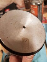
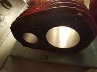
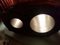
Oversize pistons should have the oversize stamped into the piston crown. The block will also usually be stamped, i.e. .010". If there is no marking on the piston crown it is a standard size. May even have STD stamped into it.

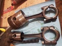
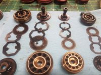
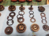
If it were mine, I'd put in new discs and springs. DeVilbiss springs aren't the greatest even when new. When they go off, they can wad up inside the cylinder and create a big mess. Rock the iron HP pistons back and forth along the length of the wristpin. The hard pin in the iron pistons tends to fret and introduce a lot of slop. This gets noisy and causes lots of bore wear.

I'd lap the valve seats on some 400 grit sandpaper on a very flat surface, like a surface plate, a thick piece of glass, or a marble cutting board. Just give them enough figure 8 motion to get a nice clean bright seating ring.

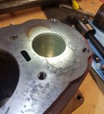
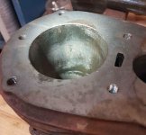
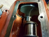
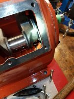
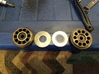
Bottom ends are unbreakable if it wasn't run out of oil. Make very sure when you reassemble it that the oil slinger rings are running below the retainer pins, or else you will seize up the pump in short order. I used to build up these pumps, and while the head was still off, fill them with oil and flip them upside down to make sure the wristpins were very well oiled. I had a couple tie up on me due to a lack of start up lubrication. Make sure the small square breather holes between the bores are plugged before you try that. The make sure you unplug them again.

Make sure you back off the retainer screws in the valve caps before you reinstall them in the head. If you try to torque them down the the screws out too far you will likely break either the cap of the valve.

You might get better pricing from eCompressed Air for parts. DeVilbiss/DeVair/DV Systems has rationalized a lot of parts over the years, so instead of buying a new piston, you now have to buy the whole rod assembly complete, which lowers inventory costs I suppose, but not repair costs. I would stick with original DeVilbiss valve parts, as some knock off springs were of pretty **** quality, which isn't saying much compared to the OEM.
 
Last edited:
OP
H

hawkerxj

Well-known member
Joined
Jul 19, 2016
Messages
65
Location
Miramichi NB
All the pistons have seem to have STD stamped on them, so they seem to be original. I measured the HP bores to be a around around 1.750 +- about 4 tenths. I'll try rocking the HP pistons again, but there didn't seem to be any play, I didn't slide the wrist pin back and forth though. I don't yet have tooling to measure the LP bores, but in watching a Quincy rebuild on youtube, the guy just verified the skirt clearance with a feeler gauge and called it good. Any thoughts on that method? He also ran the pump without the heads to seat in the rings. I've heard people recommend running it with no load, but never heard of running with no heads. It does seem like it would be good to verify it won't be blowing oil all the time.
I haven't quite got to the slinger rings yet, but will look into what you said about being below the pins. For now I have to figure out how to get the flywheel off.
While thinking about removing the fly wheel I was just spinning it slowly and heard a few clicks from the CPR(old style). The valve lever would occasionally move and click against the housing. I haven't taken it apart yet, and don't know how this older style works. I'm not sure, but I don't think the was the normal operation of it.
As for the caps and set screw, a guy over on a tractor with a similar writing style to yours, detailed the valve re-installation process pretty good.

I checked ecompressed air for parts but the don't seem to have much DV stuff. I searched for OK-432 rebuild and they have it for $586 us but describe it an Ingersol Rand kit. Seems expensive and for the wrong brand, I may have to call to verify.
The bottom end looks good, once I get the crank out, I check the journals, but they don't appear to be worn or damaged.
 

Attachments

  • 20190201_232627.jpg
    20190201_232627.jpg
    74.7 KB · Views: 55
  • 20190201_232638.jpg
    20190201_232638.jpg
    56.9 KB · Views: 53
OP
H

hawkerxj

Well-known member
Joined
Jul 19, 2016
Messages
65
Location
Miramichi NB
For today I lapped the valves bodies today and that was way quicker than I figured maybe 10 minutes to get nice smooth sealing faces. So then I went to have a look at the CPR. The little brass lever that actuates the release valve was moving when spinning at a constant speed, so I figured there was something wrong. Also it doesn't actually push the valve when stopped, so I guessing someone adjusted it improperly.
It turn out there is about 0.030 runout on the shaft. Probably wasn't the best idea to give it a big spin with those loose ball bearings in there, but they didn't go flying all over the shop. I don't think this is part of the crank based on the bolt length and parts list, but wanted to see if anyone could comment on the before I go and try to knock it of tomorrow. Also someone way overtorqued the bolt holding the CPR to the crank, you can see stretch and the necking in the threads in the pictures.

Edit: After cleaning and re-installing the CPR shaft with a new bolt, there is way less run-out, and adjusting the release valve in seems to allow it to actuate.
 

Attachments

  • 20190203_002512.jpg
    20190203_002512.jpg
    41.6 KB · Views: 53
  • 20190203_002445.jpg
    20190203_002445.jpg
    52.7 KB · Views: 54
  • 20190202_214713.jpg
    20190202_214713.jpg
    107.3 KB · Views: 48
  • 20190202_213007.jpg
    20190202_213007.jpg
    126.8 KB · Views: 55
Last edited:
OP
H

hawkerxj

Well-known member
Joined
Jul 19, 2016
Messages
65
Location
Miramichi NB
So I'm starting to put this back together, and I must be missing something, but what? The tank has two 3/4" npt ports on the top, one had the manifold in it (pictures below) and the other had an adaptor and a 1/4" copper tube going about half way down in into the tank, maybe 3ft. What would be the purpose of this?
The manifold has three 1/4"ports on the top(plus the check valve port), I need to mount the gauge, pressure switch and pressure relief valve. The check valve a small a tee with two 1/4" copper tubes coming off of it on the. One of the copper tubes goes to the CPR, to blow off pressure, but what would the other one be for?
These line were all disconnected when I got it, so I don't have reference picture to go back to.
Thanks in advance,
Hawker
 

Attachments

  • Copper tube.jpg
    Copper tube.jpg
    78.3 KB · Views: 48
  • Manifold 01.jpg
    Manifold 01.jpg
    94.4 KB · Views: 58
  • Manifold 02.jpg
    Manifold 02.jpg
    87.7 KB · Views: 54
OP
H

hawkerxj

Well-known member
Joined
Jul 19, 2016
Messages
65
Location
Miramichi NB
Getting ready to per her back together, do you guys try and seal the threads of any bolts going into the crank case?
I honed the cylinders and they cleaned up ok, there is some rust pitting on one of the low pressure cylinders, but I'm going to try it and see what happens. There are some minor imperfections in both HP bores also.
Got the bottom end together and then had another look at the parts list, and ****, part 66, WTF is that, a felt washer, I didn't see a felt washer in there when I took it apart. How critical is that part?
 

Attachments

  • Assembly (7).jpg
    Assembly (7).jpg
    77.8 KB · Views: 54
  • Assembly (5).jpg
    Assembly (5).jpg
    88.2 KB · Views: 50
  • Assembly (3).jpg
    Assembly (3).jpg
    45 KB · Views: 54
  • Assembly (2).jpg
    Assembly (2).jpg
    39.3 KB · Views: 49
  • Felt Washer.JPG
    Felt Washer.JPG
    99 KB · Views: 51
To avoid these ads, REGISTER NOW!
OP
H

hawkerxj

Well-known member
Joined
Jul 19, 2016
Messages
65
Location
Miramichi NB
Found a picture of how the tank was plumbed originally, the small tube in the middle actually goes about 3' down into the tank. I don't know what that was for, if anyone knows, please fill me in. Also the 2 copper tubes coming off the check valve in the manifold, one goes to the CPR, but I don't know what the other is for. Again, let me know if you have any ideas. Unless I figure those out, I'm just going to run one line from the check valve on the manifold, over to the CPR and give it a go.
 

Attachments

  • Tank Plumbing.jpg
    Tank Plumbing.jpg
    72.8 KB · Views: 61
OP
H

hawkerxj

Well-known member
Joined
Jul 19, 2016
Messages
65
Location
Miramichi NB
You guys have any tips for installing the cylinders back on? I have the rods/ pistons installed on the crank. I considered removing the pistons and installing them in the cylinder first. I tried to take one of the wrist pins off and it seems to be very stiff in the rod and I don't want to risk damaging it unless that is just the way it has to be done.
 
OP
H

hawkerxj

Well-known member
Joined
Jul 19, 2016
Messages
65
Location
Miramichi NB
Finally got it buttoned back up and it was running good for over a week, so I figured I'd make a payoff video. Ahh Sh#*.
 
OP
H

hawkerxj

Well-known member
Joined
Jul 19, 2016
Messages
65
Location
Miramichi NB
It appears to be the gaskets on the interstage cooler. At first I though it was the inter-stage safety valve, so I replaced it, but didn't fix the problem. Then I figured it had to be the belts, so I fabbed up an adjustable motor base. This also helped get the belts away from the reservoir, but it still sounded like that.
So tonight I sprayed it all down with soapy water and found the gaskets were leaking. The gaskets look fine, but the flanges on the intercooler appear to be twisted.
 

Attachments

  • Flange SM.jpg
    Flange SM.jpg
    80.2 KB · Views: 64

MacMcMacmac

Well-known member
Joined
Oct 21, 2014
Messages
1,578
Location
canada
Yeah, I've filed a few back to square before. Sometimes people go nuts with the torque and warp them.

That's a very fine compressor. It's good to 7.5hp too if you ever feel the need. Really overbuilt as a 5hp unit. The felt washer isn't really important. Most new bearings are sealed anyway. I used to pop out the inner seal to get oil to the bearing, and keep the outer seal to help it stay oil tight.

You are right, you only need the one copper line going to the CPR. The balls inside are supposed to be loose so they can ride in and out by centrifugal force.

I would seal up the block bolts with silicone since they love to sweat oil.

If you need to pull the flywheel in the future, just back off the center bolt and smack it STRAIGHT on with a sledge hammer while applying force from behind with a prybar and it should pop right off the taper.
 
Last edited:

Faster_Gun

New member
Joined
Nov 4, 2019
Messages
2
Location
Michigan
I want to hijack this thread as I find myself in a similar situation as hawkerxj.

My lucky self was on Craigslist Free at the right time and I picked up a 60 gallon on Sunday. Up until this point I have hydro tested the tank to 300psi and it held for 10 minutes. The valves were handed to me in a box when I picked up the compressor. The pump turns freely by hand and the bores look okay. Pistons are STD.

Yesterday I was cleaning and examining the valves and noticed two of my LP valve disc are heavily grooved matching the valve body while others are nearly flat. Example attached.
I have no history on this pump, is this to be expected with a lot of hours?

Is there a source for springs only? My springs look okay with the exception of one LP spring which has a chip out of it. Id hate to destroy a bore putting a known bad part back in.

Ordinary I would have no problem buying a head overhaul kit and I expect I will in the future but I have too many unknowns right now. The largest being a 5hp 3ph with no history and no way to power it. Right now im looking to get everything to "good enough" point so I can test it.
 

Attachments

  • 0.jpg
    0.jpg
    56.9 KB · Views: 52
  • 1.jpg
    1.jpg
    125.3 KB · Views: 53

MacMcMacmac

Well-known member
Joined
Oct 21, 2014
Messages
1,578
Location
canada
Yeah, those discs are done. I wouldn't risk putting them back in. Its best to do everything at once when overhauling valves. Otherwise you might end up chasing problem after problem as each individual component reaches its end of life.

That cracked spring is a much bigger problem waiting to happen. If it lets go it can ruin the bore, the head, a valve or the piston crown depending on how it crumples up inside the cylinder.
 

Faster_Gun

New member
Joined
Nov 4, 2019
Messages
2
Location
Michigan
New valve disc, gaskets, and a Weg 5hp single-phase. We're up and running. When the compressor stops its lets out a wub -wub -wub -wub. Is this to be expected? Unloader adjustment needed?

I plan to give it some love with a wire wheel, primer, and paint once spring rolls around.

Edit: Im tripping a 30a breaker with this 5hp in the cold weather. Im optimistic an oil change with some 20w will help this, otherwise ill be re-doing the wiring and breaker.
 

Attachments

  • IMG_20200109_123800217.jpg
    IMG_20200109_123800217.jpg
    156.9 KB · Views: 49
Last edited:

84prerunner

Active member
Joined
Feb 18, 2018
Messages
32
I doubt the oil change will be enough to make it reliably start in the cold. I had a 5hp 3phase on a static phase converter, didnt like starting in the cold on a 30amp breaker. I usually had to "bump" the compressor 4-5 times (2ish seconds each) then it would usually start without popping the breaker. I put a clamp meter on it at one point and was seeing something like 90amps on start up. My fix was putting a VFD on it and soft starting, less than 20amps starting now and will even run off my HF generator lol
 

MacMcMacmac

Well-known member
Joined
Oct 21, 2014
Messages
1,578
Location
canada
New valve disc, gaskets, and a Weg 5hp single-phase. We're up and running. When the compressor stops its lets out a wub -wub -wub -wub. Is this to be expected? Unloader adjustment needed?

I plan to give it some love with a wire wheel, primer, and paint once spring rolls around.

Edit: Im tripping a 30a breaker with this 5hp in the cold weather. Im optimistic an oil change with some 20w will help this, otherwise ill be re-doing the wiring and breaker.


It is normal for the compressor to run a few revolutions at shutdown, which will cause the valves to operate with a slight moaning sound.

If you are not getting a blast of air out of the unloader at shut down then it will need adjustment. Have a look at the back bearing carrier where the unloader is. When it shuts off the little lever should move sideways and push a plunger to open a poppet valve to drain the air off between the check valve and the pump. If it moves but no air comes out, let the copper line off, loosen the large thin jam nut on the brass fitting and screw it in a few threads. Re-attach the line and run the compressor. If it bleeds air the whole while the compressor runs, it is in too far and needs to be backed out a little. It might take a few cycles, but it is an easy adjustment. If you can't find a setting that works, you may need to repair the unloader mechanism, as they wear out over the years from the pot metal pads rubbing against a hardened steel surface.

30W oil is definitely too heavy for a cold room. If you looks at the DeVilbiss recommendations on the metal tag, you will see that they specify very light oils. This is important to get the lubrication up to the wristpins asap. Other than carbon buildup from using engine oil, wristpin wear is the bugaboo of most reciprocating compressors. Most people run too heavy of an oil in their machines.

If you don't have any relief valves in your intercoolers, install some 60psi units as soon as practical. These will give early warning of valve problems.
 
Last edited:
To avoid these ads, REGISTER NOW!
Top Bottom