To avoid these ads, REGISTER NOW!

Drill press won’t spin

exmaxima1

Well-known member
Joined
Jun 25, 2011
Messages
6,348
Location
Midwest
Yep, it was the centrifugal switch. I removed it and sand the contact poles. And it spins freely again. Thank you everyone.
My next question was that if these motors can be turn CCW, but dogdog answered that question already. Thank you so much guys!!!!

WTF? I thought you said you tried BOTH motors and neither worked. And that spinning it by hand at startup made no difference? It is mind boggling that cleaning the switch now makes any difference.....
 
To avoid these ads, REGISTER NOW!
OP
N

Neto_09

Well-known member
Joined
Dec 22, 2017
Messages
52
Location
Santa Ana California
Yes they can be made to go either directions, but it requires you to Modify and separate the start coils from the run coil, the connection is embedded into the winding inside... and put everything back together nicely without burning up into flames.. I did it on my Jet drill press, just for the heck of it... Originally the motor was just squeaking I don't like it. But since I have the motor out and open, figure just to modify it for CW/CCW.. No real practical use for me but it works.

Do you have by chance any pics, or info about the mod? I would like to try doing it. Or the link that you mentioned earlier. Thanks.
 

dogdog

Well-known member
Joined
Nov 15, 2011
Messages
12,711
Do you have by chance any pics, or info about the mod? I would like to try doing it. Or the link that you mentioned earlier. Thanks.

https://www.garagejournal.com/forum/showpost.php?p=6549450&postcount=17

this is all I have in pic wise ... I have to put in a DPDT switch for 120V arrangements... I don't remember where I post those pics... The basic idea is if you switch/flip ONLY the connections of the start coil (say from L1 to L2 and L2 to L1) then the motor will go the other way... Leave everything else intact.. (everything else means your voltage arrange for the W1 W2 run coils)

If you are doing it for 240V arrangement, then the switch wiring would be different a bit different.


**** Oh right... the pic are on the next post.

https://www.garagejournal.com/forum/showpost.php?p=6557090&postcount=18


Let me see if I can find a better reference on youtube... explaining it in writing is not my forte..

Basically it is a DPDT without Center off (1HP draws about 768Watt about 10AMP so size it accrdingly, say a 15AMP switch).. and it works in supplement with the drill press on/off switch. Only used to flip the starting coil connections.

The two center pin connections goes to the coils L1 and one goes to L2 connections.

The outer pins are cross connected one goes to one end of the start coil where it used to connect to L1... the other goes to the other end of the start coil circuit (where the capacitor or the centrifugal switch used to connected to L2) , in this case I flipped the coil/switch/capacitor too... Cap is AC so it doesn't care.l


I think the bottom of page 2 and also page 3 explains the operation of reversing the rotation of induction motors... you just have to read through it. and most people use that drum switch for switching rotation, also On/off combine... which is a TPDT WITH center off... and the arrangement automatically flips the connections for you I think... Never got to digest that part for me, so I just use DPDT what I have at hand.

https://www.practicalmachinist.com/...lease-wiring-switch-motor-257832/index3.html?
 
Last edited:

dogdog

Well-known member
Joined
Nov 15, 2011
Messages
12,711
Since you went that far...

Just make sure you have some heat shrink at minimum or those fiberglass/silicon tubes and some cotton strings to tie things back, also connections needs to be crimped not soldered.

if you look at the start circuit on that practicalmachinist post.

https://www.imgur.com/e9Kpy.png

you'll see that the start coil circuit is from the centrifugal switch to the cap...
the cap then to the one end of the coil... then coil then to L1 ...

the coil is sort of imaginary, you won't see them in those bird's nest of wires... but you do know it is connected on the other end.

so follow one of the capacitor wires to the wires that is embedded inside ...

and from your motor voltage connection plate , it shows 1&3 a and 2&4 would have put the run windings in parallel...
so that means the combination of 1&2 or 1&4 might be one coil and 2&3 or 2&4 might be another run coil.. ohm or continuity would have confirm it once you have all the wires taken out / exposed.

attachment.php


on mine, it is the bulkier bunch then crimped and tied and sleeved with those fiber glass or silicon tubes and hide inside. YMMV.


***You do know if you are doing this mod, you voided your warranty right ? So better put on your safety and common sense on.
 
Last edited:
OP
N

Neto_09

Well-known member
Joined
Dec 22, 2017
Messages
52
Location
Santa Ana California
Once I locate them, splice them and I’ll get two wires, right? And then crimp one wire to each one, right?
So, the wires that I found in the winding, let them alone? I’m not supposed to do nothing to them? Or what I’m supposed to do with them?
 

dogdog

Well-known member
Joined
Nov 15, 2011
Messages
12,711
Once I locate them, splice them and I’ll get two wires, right? And then crimp one wire to each one, right?
So, the wires that I found in the winding, let them alone? I’m not supposed to do nothing to them? Or what I’m supposed to do with them?

Once you locate them, you would want to separate each wires out so that you have two wires out from each individual coils..

and don't forget about your TCS(thermal cutoff fuse)... I don't have that. but since you do, you'll have to devise a plan to include that in your things. (some motor have them some don't, but it needed to be embedded or place close to the laminated steel or coil I think) That thing is for cutting off the electricity flow when it reach a certain temperature... and resets when temp cools down.

I think those wires that came out are 14 gauges stranded, don't know if it is machine wires or not, I used the one I got from a pc desktop power cord, but if you have access to proper machine tool wires, you should used them.
 

dogdog

Well-known member
Joined
Nov 15, 2011
Messages
12,711
My motor doesn’t have a TCS.
How about the ends that I found?

that pic from post 17 says you do... that is usually embedded into the coils or tied near a coil / not usually a visible component but usually on cheaper motors......I don't know if you really do or not, I wouldn't want to bypass it if you do have it.

As far as the pic you posted... I can't tell what they are just from looking... needed to test them with multi-meter. and the only hint I can offer is start from the centrifugal switch/cap and use that diagram to help you track which is which.... one of the end have to lead to one end of the coil... from there the other end of the coil is embedded ...

for me, I have to cut those cotton strings and dig out the silicon/fiberglass sleeve covered connections and break them out. and mark them with each test.
 
OP
N

Neto_09

Well-known member
Joined
Dec 22, 2017
Messages
52
Location
Santa Ana California
Well, I’ll keep digging. I will post any progress later in the week, I work all day the next two days. This is very interesting, when i was in high school back in Mexico, we used to have this “shops” that in some way, if you couldn’t afford more schooling, they teach you (the basics) so you can find a job. I took electronics, but that was back in late 80’s early 90’s, I kind of forgot most of it. Doing this, bring me good memories!!!!
 

dogdog

Well-known member
Joined
Nov 15, 2011
Messages
12,711
We call them Vocational Tech schools or BOCES is another program here for people that are not interested in Books at least in the USA everything up to high school is still "free" for the kids via tax dollars.

Saying that, Nothing wrong with tinkering but make sure practice safety first.
 

dogdog

Well-known member
Joined
Nov 15, 2011
Messages
12,711
Are you just tinkering mess with it or is your motor still not working??

.... IMO if you have one that is working..NO, and it dependents on what you are using the drill for. Not sure how $$ it is. some general purpose motor have all the wires lead out so you can install a drum switch easier.

For those you have to look up the motor frame and match the motor frame and the shaft. if you are looking for replacement.

If I were to upgrade, I would go with a 1HP 3PH motor to get variable speed... or 2HP 3PH but that is a different story.
 
OP
N

Neto_09

Well-known member
Joined
Dec 22, 2017
Messages
52
Location
Santa Ana California
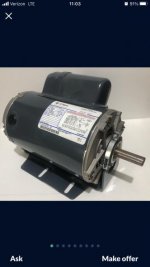
He’s asking $80 for the motor.
And yea, I kind of want to upgrade. But I have no way to put a 3ph motor in my garage. I have 1 ph 220v.
Press will be used mostly for steel fab. For my Jeep. Which means it would be used sporadically.
 
Last edited:

dogdog

Well-known member
Joined
Nov 15, 2011
Messages
12,711
He’s asking $80 for the motor.
And yea, I kind of want to upgrade. But I have no way to put a 3ph motor in my garage. I have 1 ph 220v.
Press will be used mostly for steel fab. For my Jeep. Which means it would be used sporadically.

if you have 240V at the drill press, there are always cheap China made or expensive Mexico/ US company that sells those inverters they call them VFDs.. (There is a VFD thread in this subforum pinned )
Just make sure you get the right one that fits your motor. For SUB 1HP 3pH motors I think they even have 120V ones..

Buying that GE motor at 3/4 HP.. its more of a down grade from 1HP no? unless you are just upgrading to the motor COO... and claim the Taiwan motor is just over rated with metric HP instead of imperial HP, etc.... you get NOTHING out of it other than the COO and $80 gone... A useful upgrade would have been that link on the pulley system to make it go slower... There was a link on a pulley kit on some other thread. A better chuck if your column is still good. etc.

But I don't think it is useful upgrade if that is what your intent and not an interest, especially if you are just sporadically using it. But that is just me. If you are doing it as fun, all the ROI are out the door go ahead and throw your wallet at it. Still a down grade IMO. :)
 
Last edited:
To avoid these ads, REGISTER NOW!

dogdog

Well-known member
Joined
Nov 15, 2011
Messages
12,711
Sorry to disappoint you, No expert here, just some one that have been there done that with strong opinion.

Hopefully an Expert will chime in and give you their two cents of thoughts.

GLHF
 
Last edited:
OP
N

Neto_09

Well-known member
Joined
Dec 22, 2017
Messages
52
Location
Santa Ana California
Hey, you know more that me, so, that makes you an expert. I found something, I hope you can still guide me.

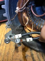
B2570BCA-92FA-4A8F-AF7B-AB077A49F25D.jpg

In this one, I follow the wire that comes from the cap, there’s only one wire that goes into the winding and gets lost

8FDA26AE-9E03-4AC2-ADAD-381083A7CF69.jpg

On this one, ?2 it’s one of the “ends” that I found into the windings, this end have continuity with the wire that goes to the cap. This end wire doesn’t have continuity with any other wire

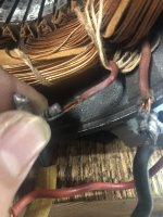
D3D29401-0647-4452-B061-BEE353ED5451.jpg

In this one, ?1, has continuity with 1-4.
 
Last edited:
OP
N

Neto_09

Well-known member
Joined
Dec 22, 2017
Messages
52
Location
Santa Ana California
I measured ohms.
2-3 =1.2
1-4 =1.2
Wire to cap + ?2 (end wire)= 1.9
Now I measured ?1 with the ones that have continuity and this what they read:

?1+wire #4=3.1
?1+wire #1=1.9
 

dogdog

Well-known member
Joined
Nov 15, 2011
Messages
12,711
in my case the start winding (w3) was approximate 2x ohm value of the W1 or W2 ( run windings)

when all wires are separated out, you should have 3 set (6 wires) of wires (maybe 4 sets (8 wires) if you do have tcs) make sure you kept the 1 2 3 4 marked it is important.... otherwise if you get it lost the magnetic field generated might cause problems to the spinning rotors, if you get those reversed....

as far as the wires gets lost, it's probably inside those yellow tubes that is either fiber glass or silicone (they are a bit tougher than heat shrink.) Your TCS is probably inside there too.. The strings that tie them together is just regular cotton string I think... Mine was inside those tubes, I have to cut the cotton strings and free them carefully... Keep in mind before you start this is almost the point of no returns.... so...safety first yea even thought it's 120V it's consider high voltage that can kill you... sorry bud. probably not a great thing to advise in a forum.. and probably a lot of experts hesitate in answer you these kind of questions.

when I was modding mine and void warranties, I think I remember some of the supplies needed are.

make sure you have some cotton strings
some good size plastic ties
some silicone / fiber glass tubing, just few short pieces of 1" or 2"
few pieces of 14 gauge stranded preferably machine tool wires...MTW wires
and crimp connectors to crimp the wires back together. They are mechanically tied together as oppose to soldered. I used the end of a small 18 or 22 gauge or so crimps and snipped off the ends I don't need.


****I don't know what that ?2 marked wire is in your pic. That might be one end of your start winding... was it connected to something like 4? or 1?
 
Last edited:

dogdog

Well-known member
Joined
Nov 15, 2011
Messages
12,711
maybe this give you a better visual...Hope it makes sense conceptually... not even sure what I type these days. SO take it with a grain of salt. Do your own homework.

looking at the low voltage of the motor winding ...

http://www.industrial-electronics.com/AC-DC-motors/41_Changing_Voltage.html


12-42.jpg


you'll see some similarities.. .T1 T2 T3 T4 those are your wires that comes out. (cant be sure about your situation).. lets say (assume for a bit) Those are your 1 2 3 4 wires.

what you don't see is the T5 and T8 (connections to the start windings) those are usually embedded inside those yellow fiberglass tubing for motors that are wired to go only one directions. Don't ask about T6 T7 T5 is actually the cap I think (5 6) 7,8 is the real start winding)... I don't remember where I read it, but vaguely remember those might be the ones either for the centrifugal switch or caps.they are all in series with the start windings so they are treated as start part of start coil in conceptual thingy. (I think) so 5 and 8 is the two ends of those Terminals that are part of the start winding.


Now look at your motor instructions. it says to take T2 and T3 connected together and you will change it to higher voltage mode... effectively you are putting the two run coils in series. ... without understand anything at this point.

Next look at the High voltage configuration and you will see that T5 is connected to T2 T3... but T2 is moveable.. so... That means T3 is connected to T5 Permanently. compare to the low voltage and high voltage, only points that move is T2... so... you'll find T3 and T5 embedded inside those tubing somewhere.

Comparing High voltage and low voltage configuration, you can see that L1 is always connected to T1. L2 or Neutral is Always connect to T4 and T8... so this tells you that the connection for T4 and T8 is embedded... somewhere.


if you have TCS... then TCS is in series with the connections of T4 and T8. (maybe...but it doesn't make sense... somewhat, so I don't have TCS or encounter one so...)

To make these AC induction motor reversible, the goal is to find those and separate out T5 and T8 and use a drum switch or a DPDT switch + on/off switch to logically switch the connections of T5 and T8
 
Last edited:
OP
N

Neto_09

Well-known member
Joined
Dec 22, 2017
Messages
52
Location
Santa Ana California
I’ll dig deeper on the fiber glas tubes then. I have cotton strings, plastic ties and the silicon heat shrink.
?2 and ?1 are the ends that I found, they were soldered together, i unsolder them and that’s how I got them. ?2 and the wire that goes from the cap to the windings, seem to be the same winding or at least to be connected in some point.
I’m going to put them together again and look for the wire that you told me. Thank you so much for your patience and knowledge.
 
OP
N

Neto_09

Well-known member
Joined
Dec 22, 2017
Messages
52
Location
Santa Ana California
This is what I found today. All 4 wires. 2 have 2 winding wires, one has 2 winding wires and it has attached a wire that goes to the centrifugal switch and the one on the picture that shows 3 winding wires.
843E1667-60AD-4554-89C3-0ECC785AA126.jpg

A5E5ED81-6F60-46F6-861D-5D883047C017.jpg
Is this the one!!!!
 
Last edited:

dogdog

Well-known member
Joined
Nov 15, 2011
Messages
12,711
Sorry Neto, I won't be able to tell anything without physically at the motor. Maybe some one can... That is because what I see might not be what you see. and Not all motor manufacture follow one way to embed those wires... ie color coded or always at the left or always at the right etc.

read that post#64 is what I interpret of the motor windings...

Might be easier if you draw the low voltage winding on paper with pencil then move the connections manually to look like the high voltage circuit.

if you have separated the connections.
the W1 W2 are equal in ohms, W3 usually is higher ohm than W1 or W2... usually it's 2x the value but not always the case.


the other thing also to note is W3 is always parallel to W2... in high voltage or low voltage mode.

SO the two that have two motor winding might be W2 (one of the run winding) and W3 ( start winding), I won't know for sure looking at pics. you'll have to confirm.
 
Last edited:
OP
N

Neto_09

Well-known member
Joined
Dec 22, 2017
Messages
52
Location
Santa Ana California
One question. In your motor, your color wires, how many winding wires were connected to each wire? In one of the pics that you posted, the yellow wire seems to had 3 wires, because I can barely see that there are two crimped to the yellow wire and the one that you separated and crimped the black wire.
 

dogdog

Well-known member
Joined
Nov 15, 2011
Messages
12,711
Not 100% sure it's been almost 4 years...yes motor still runs and drill still works... but looking at the pictures.

Yellow wire in the original 1/6 pictures. has the number 4... if you look at the pic of the high voltage winding... it have T4 and T8 permanently crimped in there. Why didn't it have T2 like in the low voltage diagram? That is because the T2 connection is made outside so you can change it... remember moving T2 to T3 and disconnect T3 from T1 changes the run windings from being in parallel to be in series. That is why understanding that low voltage/high voltage diagram is important.

so if you look at the pic 3/6 the T4 and T8 are separated, and the Yellow wire only have one connections which is T4 only that goes out.

T8 at the end I believe I used the 14 gauge wire stripped from a computer power cord. so it should be either black or white (looking at pic 3/6 it looks like I have used the Black wire for this), I don't remember.. but you'll see 5 or 6 wires that came out at the end of pic 6/6...all the winding and connections are separated.

looking at my old photos , it looks like my T8 is one end of the start winding, which is black wire.

The other end (blue wire) of the start winding goes to one of the start capacitor connections.... then there is a blue wire goes to the centrifugal start switch... from the other end of the centrifugal switch..I think there is another wire (should be a new white wire I stripped from power cord)... this is one of the wires that goes to the DPDT or drum switch that will be flipping for making the motor rotates in different directions. Of cause that black wire from T8 is the other one.... in my case.
 
Last edited:

dogdog

Well-known member
Joined
Nov 15, 2011
Messages
12,711
Dogdog!!!!!! I did it!!!!! I reversed the motor!!!!!!!

:beer:
:thumbup:


Congratulations. Now you have a drill press that goes reverse... probably a function that will never get used :) maybe one day it is useful for left hand drill bits.
 

dogdog

Well-known member
Joined
Nov 15, 2011
Messages
12,711
LOL... ok...I would go for the 1.5 HP one too.. it's an upgrade. but really a gear / pulley reduction is more useful functioning wise.
 
To avoid these ads, REGISTER NOW!
Top Bottom