To avoid these ads, REGISTER NOW!

Electronic troubleshooting

OP
S

Snapped-off

Well-known member
Joined
Feb 22, 2012
Messages
4,812
Location
Indiana
Guess I missed that. I haven't been following and just scanned through looking for something more on that. That's a big help to know those things. The voltage isn't going to be high on battery powered toys so that shouldn't be an issue. Only other thing is gain but that may not be critical.

I was just recalling a similar fault years ago on some military gear. The spare circuit card was pulled from stock and didn't fix the problem. Standard proceedure was to just replace cards so they really didn't have training going down to the component level. Wasn't essential gear for the current situation so the team went to bed with it unsolved. I and a buddy had the night watch and I found a transistor that moved more than expected. Cracked lead. Woke up the storekeeper to get the replacement and got it fixed.
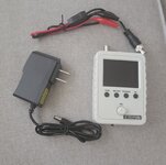
The initial problem was a weak or broken lead with the transistor. Some wiggling got it working again. I probably over wiggled it as I found the base lead was broken and everything quit. Since then it's been dead. Hence all the further troubleshooting.
 
To avoid these ads, REGISTER NOW!

RPH

Well-known member
Joined
Dec 17, 2006
Messages
4,190
Location
Michigan Thumb
Well that switch wiring is busy. How does the switch activate? The yellow wires show two to the device and two switches with 3 traces on the board proper. Waiting for the scope, we need to look at the signals coming and going out, if any. Don’t quit, look at what you have learned.
 
OP
S

Snapped-off

Well-known member
Joined
Feb 22, 2012
Messages
4,812
Location
Indiana
You drive the train over the red part on the track, it pushes down onto the little grey rubber standoffs and completes the circuit on the board. I can take a picture of it if needed. What kind of switch is this? It's not like any switch I've ever seen.
 

RPH

Well-known member
Joined
Dec 17, 2006
Messages
4,190
Location
Michigan Thumb
Depends on the cob. But ya, take a pic. How many of the switches can be hit at once? More than one car over multiple switches? Wheels activate them? Magnet? Cam?
 

dave*99

Well-known member
Joined
May 5, 2009
Messages
4,280
Location
Coastal NJ
You drive the train over the red part on the track, it pushes down onto the little grey rubber standoffs and completes the circuit on the board. I can take a picture of it if needed. What kind of switch is this? It's not like any switch I've ever seen.
There is a chance that switch consists of a printed circuit pattern with 2 electrodes on the main PCB. Under the gray cap may be a black rubber part that is an impregnated rubber part that is "conductive" The electrodes are connected to a high impedance input on the IC. Pushing the conductive rubber down on the electrodes completes the circuit.
 
OP
S

Snapped-off

Well-known member
Joined
Feb 22, 2012
Messages
4,812
Location
Indiana
There is a chance that switch consists of a printed circuit pattern with 2 electrodes on the main PCB. Under the gray cap may be a black rubber part that is an impregnated rubber part that is "conductive" The electrodes are connected to a high impedance input on the IC. Pushing the conductive rubber down on the electrodes completes the circuit.
That's exactly what it is. I've already looked at it. Just not familiar with it and I've never seen one prior to this.
 
OP
S

Snapped-off

Well-known member
Joined
Feb 22, 2012
Messages
4,812
Location
Indiana
Depends on the cob. But ya, take a pic. How many of the switches can be hit at once? More than one car over multiple switches? Wheels activate them? Magnet? Cam?
You just drive over them. You can push them down by hand. Dave's post describes exactly what they are.
 

RPH

Well-known member
Joined
Dec 17, 2006
Messages
4,190
Location
Michigan Thumb
Ok, just checking. I’ve seen many different creative ways to utilize inputs to generate the output.
 
OP
S

Snapped-off

Well-known member
Joined
Feb 22, 2012
Messages
4,812
Location
Indiana
Gotta figure out how to set this up. :lol:

I've played with a real scope before but this ones a little different.
 
OP
S

Snapped-off

Well-known member
Joined
Feb 22, 2012
Messages
4,812
Location
Indiana
Any suggestions on setup as far as input voltage and waveform duration? I'm trying to figure out if I can zoom into the waveform so it's visible.. it's so small it's almost a straight line.

I have black to B- and red to transistor base.

Am I reading AC?
 

RPH

Well-known member
Joined
Dec 17, 2006
Messages
4,190
Location
Michigan Thumb
No calibration for the probe? Instructions? Start with dc and see what you get.
5 v/div to start is safe, 2.5 most likely to be useful. Time base, start long and keep reducing. Your trigger will be interesting. I have never explored a scope like that. Tektronics, Flukes, and some Sony scopes mainly.
 
OP
S

Snapped-off

Well-known member
Joined
Feb 22, 2012
Messages
4,812
Location
Indiana
No calibration for the probe? Instructions? Start with dc and see what you get.
5 v/div to start is safe, 2.5 most likely to be useful. Time base, start long and keep reducing. Your trigger will be interesting. I have never explored a scope like that. Tektronics, Flukes, and some Sony scopes mainly.
Instructions are just telling what the buttons do. There's a test output on the top I assume to verify calibration.
 

RPH

Well-known member
Joined
Dec 17, 2006
Messages
4,190
Location
Michigan Thumb
On a normal scope the probe calibration is usually 5v/div @1kHz. What I would be checking is the squareness of that pulse train. Right now get that pulse train displayed and play with the controls to get a feel for it. For the price, what the heck!
 
  • Like
Reactions: Max

Max

ALLIANCE MEMBER
Joined
Jun 16, 2018
Messages
3,351
Location
Georgia
Vcc is three 1.5V batteries, right? So 2.5V or 1V per division as it’s 4.5V max. And we’re talking audio frequencies - most likely less than 10 KHz. So I’d start at something like 50 ms/div and go up or down from there.
 

Max

ALLIANCE MEMBER
Joined
Jun 16, 2018
Messages
3,351
Location
Georgia
On a normal scope the probe calibration is usually 5v/div @1kHz. What I would be checking is the squareness of that pulse train. Right now get that pulse train displayed and play with the controls to get a feel for it. For the price, what the heck!
Yep I’d get the cal signal displayed first to validate the scope is working.
 
OP
S

Snapped-off

Well-known member
Joined
Feb 22, 2012
Messages
4,812
Location
Indiana
So it has the 1khz test output. What am I supposed to do with it though :lol: when the switch is set to GND, it isolates the input leads from the input signal and grounds the scope.
 
To avoid these ads, REGISTER NOW!
OP
S

Snapped-off

Well-known member
Joined
Feb 22, 2012
Messages
4,812
Location
Indiana
Seemed weird. Took it off GND... figured out the test calibration. There's no waveform visible over 1ms. Below that down to micro? Pico? It just gets crazy.
 
OP
S

Snapped-off

Well-known member
Joined
Feb 22, 2012
Messages
4,812
Location
Indiana
Trigger is set to auto. Also has normal and single but they don't pick anything up. I don't think I'm getting any meaningful readings hooked up to the board. The cal test put out a nice square wave, but the board is putting out an erratic sine wave.
 
OP
S

Snapped-off

Well-known member
Joined
Feb 22, 2012
Messages
4,812
Location
Indiana
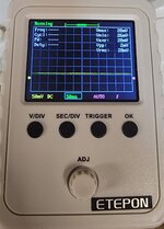
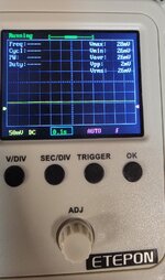
These are just sitting here hooked up to B- and the transistor base..
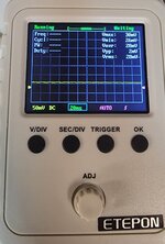
20220118_163752.jpg
20220118_163817.jpg
No changes when closing a switch.

This should be flat until a switch is closed and the COB sends out a signal right? I'm probably wrong somewhere.
 

RPH

Well-known member
Joined
Dec 17, 2006
Messages
4,190
Location
Michigan Thumb
Nothing at collector? Drop the voltage do enlarge the trace, and stretch the time out. The beauty of a scope is seeing the waveform.
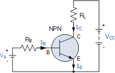
Transistors are used as a switch or amplifier depending on need. On the npn unit the “P” has to be more more positive than the collector. Only then does the current flow. The more positive it becomes the electrons move until in full conduction. To shut off you apply negative voltage to base. Opposites charges attract = current flow. Like charges repel = no current flow. This is why my questions on the switches and what initiates the cob to output. Not sure if we have done that. Not a bad picture on the scope.
AA853487-67C6-4ED2-8F57-82413FA7056D.png
 

FordTruckWench

Well-known member
Joined
Jan 8, 2015
Messages
539
Location
California

This looks like your picking up wall current. Sensitive instruments will easily pick up the 60Hz AC.

In practice, this means that nothing is driving that point in the circuit. Or you scope isn't fully hooked up.

...

Now that you have the scope, I'm interested in what sort of signal is on the business end of the yellow-violet-yellow resistor. (The end not hooked to B+.) Previously you said that the voltage changed when you pushed the buttons.
 
OP
S

Snapped-off

Well-known member
Joined
Feb 22, 2012
Messages
4,812
Location
Indiana
The problem was the waveform wasn't getting bigger or longer while I was adjusting it.

It was working as expected while I was messing with the cal test. I'll get to it some more in a bit. I'm off today.
 
OP
S

Snapped-off

Well-known member
Joined
Feb 22, 2012
Messages
4,812
Location
Indiana
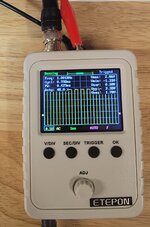
Hooked up to B- and transistor base. Nothing meaningful. I'll try the collector and the resistor as well. Went up and down with voltage as well as duration. Above 50mV just looked flat. Below 50mV didn't look any better.
20220119_094551.jpg
20220119_094559.jpg

20220119_094613.jpg
 
OP
S

Snapped-off

Well-known member
Joined
Feb 22, 2012
Messages
4,812
Location
Indiana
Just some pics of the 1khz cal test. It does seem to work. Also for the above pics. I was closing the switches and not seeing any changes. I'll keep playing with it.
20220119_094804.jpg20220119_094811.jpg20220119_094823.jpg
 

RPH

Well-known member
Joined
Dec 17, 2006
Messages
4,190
Location
Michigan Thumb
Ok, so we have confidence in the scope.
Do you have power into cob? Across the inputs, that change of state thing.
Then probe cob at transistor leads with no transistor in the socket.
All except transistor socket should be dcv. Either it’s present or not.
At this point just verify the conditions.
 

dogdog

Well-known member
Joined
Nov 15, 2011
Messages
12,711
the thing with these single transistor amplifier is the base is where the sound signal comes in from... maybe try with the transistor unhook... the test lead to the base pin and the ground to ground pin (the E) ? and press the button, it should output something.
 
OP
S

Snapped-off

Well-known member
Joined
Feb 22, 2012
Messages
4,812
Location
Indiana
I've updated the first post in red. I found a cheap and supposedly working track half on ebay. (The half with the circuit board.) Is there any risk in cooking the chip by hooking the scope up to it and messing around with it?

I kind of just want to mirror some testing with the good and bad boards to confirm the original one is toasted. I don't want to ruin the 2nd one though. :beer:
 

Max

ALLIANCE MEMBER
Joined
Jun 16, 2018
Messages
3,351
Location
Georgia
Glad to see that you are still in it. :)

The ‘scope should be high impedance so no issues there unless you short something with a probe. Just make sure the board gets hooked up ok.
 

RPH

Well-known member
Joined
Dec 17, 2006
Messages
4,190
Location
Michigan Thumb
For a moment there I thought you were experiencing the seven stages of grief. Just be careful poking around.
 
OP
S

Snapped-off

Well-known member
Joined
Feb 22, 2012
Messages
4,812
Location
Indiana
Got the new track piece in, it works. I definitely get working results on the oscilloscope. I have it hooked up from transistor base to emitter.

The original transistor is in fact a S8050.
 
OP
S

Snapped-off

Well-known member
Joined
Feb 22, 2012
Messages
4,812
Location
Indiana
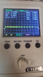
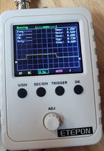
Couple pics of the scope while closing switches. The last one I pressed it 3 times which you can clearly see. Pretty neat for under $40.
20220204_145439.jpg
20220204_145453.jpg
20220204_145625.jpg
 
To avoid these ads, REGISTER NOW!
Top Bottom