To avoid these ads, REGISTER NOW!

EMT surface mount outlet plan

GirlnAgarage

Well-known member
Joined
Jan 21, 2011
Messages
4,668
Location
Texas
I'm getting near the electrical portion of my garage reorganization. The quick version is my garage has only two outlets - one on the ceiling right in the middle (garage door opener plugs here), and one on the front wall (where I run my extension cord for everything). Each outlet is on a different circuit, both are 20A. I would like to pull the ceiling outlet as my tap point for the EMT using a single box (should this be double?).

I would like to run conduit along the ceiling out to each side wall to a 90* elbow fitting and drop straight down ~48"-50" wall height double receptacle box, which will act as the 'T' to run horizontal to a single at the front of the garage and a single near the back.

I will run three conductors of 12ga wire.

My thinking & questions on this layout:
- only one vertical run down the wall minimizes what I have to work around for any wall mounted shelves, notching etc.

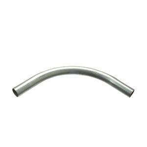
- using a 90* elbow is easier/cheaper than buying the conduit bender since the layout is very simple. My question is should I run a junction box instead of the 90* fitting? I do not really see adding any more outlets on this circuit :dunno:

- From online calculators I gathered 1/2" is the minimum to run three 12ga wires, correct? Would pulling wire be easy enough? 1/2" is 1.69/10ft; 3/4" is 3.29/10ft. I measured 58' for the layout (did not account for boxes/width/connections).

- I plan to use one GFCI outlet on the circuit. Where do I place it? I'm thinking not on the ceiling so if it pops it is easy to hit the reset button. But if it has to go on the ceiling box then it goes on the ceiling box. What do you think?

- I saw 'offset fittings'. My understanding is those connect the conduit to the box with a slight offset that holds the conduit closer to the surface of the wall while still making a straight entry into the knock out hole of the box. Is that correct? If so, I want to use those for each box.

Ok, that's my basic plan here. Would like to get this rolling but need some feedback if I'm on the right track. I do have Tauton's Wiring Complete book that explains the install pretty well (has pictures!) :lol_hitti But in all seriousness I feel confident this electrical work is in my scope of ability for not being a certified electrician. :beer:
 
Last edited:
To avoid these ads, REGISTER NOW!

Gregishome

Well-known member
Joined
Dec 29, 2011
Messages
811
Looks like a good plan.... 3-12's in a 1/2 emt is fine.

On your two gang outlet box on the wall, use a deep box 4" x 4" and put the GFI in it and then put a "modular" retangular style receptacle next to it that has the exact same dimensions as a GFI rec. ...

Wire the mod style rec on the load side of the GFI. They make covers that are designed for two ganged GFI 's but you may or may not, want to buy two GFIs rec. as they are $15.00 ea. now.
 
Last edited:

pattenp

Well-known member
Joined
Jun 4, 2008
Messages
10,175
Location
Virginia - USA
All 120V outlets in your garage need to be GFI protected. Install one GFI outlet at the beginning of each circuit and wire the rest of the down stream outlets from the load side of the one GFI outlet. That will GFI protect all of the down stream outlets.
 

WhoWhatNow

Well-known member
Joined
Feb 22, 2011
Messages
1,886
Location
Collegeville, PA
I am planning something very similar. I wrote up a plan and had a guy who is a commercial electrician take a look and make suggestions. A few things he suggested that may be useful for you:

run the conduit around the bottom perimeter of the garage. It will be easier to do and easier to modify if you need to later. It will also be less noticeable since most of it will be hidden by benches and shelving.

For a 20amp circuit I don’t think you need the ground to be 12ga as well. 14 or maybe 16 should be fine. This will make pulling wires easier.

Use the wire lube when you are pulling wires. Apparently it does make it easier.

Good luck!
 
OP
G

GirlnAgarage

Well-known member
Joined
Jan 21, 2011
Messages
4,668
Location
Texas
Thanks guys. So I guess I might not be able to split off the ceiling outlet in regards to putting in a GFCI outlet in. Instead I'd have to go one way with the conduit and go all the way around the garage to get to the other wall. Is that right?
 

JimVonBaden

Well-known member
Joined
Dec 2, 2011
Messages
15,716
Location
Northern Virginia
Is your garage detached or attached?

In my townhouse there are two plugs, one for the garage door and one for the wall plug, just one like you. NEITHER are on a dedicated circuit. The wall plug is ganged with, of all things, the ceiling lights in the master bath on the third floor, and the ceiling plug power also runs the single ceiling bulb AND is ganged to the Master Bedroom wall plugs.

Point is, there may be more load on your plugs than you realize.

If not, and verified, you have good advice already stated.

Jim :cool:
 

hammlm

Well-known member
Joined
Jun 21, 2005
Messages
676
Location
SE PA
Pulling three 12's in the 1/2, as stated will be no problem. I'd suggest stranded unless you have a source for free solid wire.

I'd also buy the 1/2" bender. It's relatively cheap, and I would think you could probably justify the cost, if not cover it entirely when you consider the cost of 90" connectors, offset connectors, etc.

Plus, learning to bend 1/2" is easy and you might just find you end up with a better job.
 

rlitman

Well-known member
Joined
Oct 18, 2010
Messages
24,596
Location
Long Island
Thanks guys. So I guess I might not be able to split off the ceiling outlet in regards to putting in a GFCI outlet in. Instead I'd have to go one way with the conduit and go all the way around the garage to get to the other wall. Is that right?

No, just put the GFI upstream, and use the "load" terminals for the hookup to everything downstream. One GFI is sufficient to protect every outlet, IF you want to put all of those outlets on a single circuit (that's a different story).

I would seriously consider using the bender though, or buying swept elbows and using two couplers (which the cost of a 1/2" bender easily offsets if you're doing more than 2, but for just one, this might be the ticket).
With conduit elbows, you take the cover off, pull the wire out, through the open cover, then send it down the other leg. That works for an "outside" corner, but not for the "inside" corner you'll be doing.
You could always "rent" (buy/return) the bender.

1/2" conduit is easy to bend. 3/4", not so much. I bent 1" conduit for a friends project. That was a huge pain. When I discussed this with an electrician, he just laughed, and said, try bending 1 1/4" then.
Anyway, 1/2" is the smallest size for 12 gauge wires, because 1/2" is the smallest size EMT you can get. It'll be just fine.

A real electrician would do an S bend at each side and not use offset connectors. I'd just get the offset connectors. Bending the offset just right can be pretty difficult (unlike the 90).
 

Gregishome

Well-known member
Joined
Dec 29, 2011
Messages
811
If it was my garage which is just gorgeous by the way:) I would run Wiremold 700 surface raceway/boxes and caulk/paint it to match the wall color, and it would look fine as frog hair.
 

Charles (in GA)

Well-known member
Joined
Jan 11, 2006
Messages
12,489
Location
50 mi south of Atlanta
As already noted, make sure of what else powers the garage door opener receptacle. You don't want any surprises.

Get an extension box, it looks like a regular box, but with no bottom, and after you remove the existing cover plate and receptacle in the ceiling, you screw this box to the existing box. You can run conduits right out the sides of this extension box, and you can install a receptacle and cover plate on it to power the garage door openers.

They make inside corner conduit fittings. The side of them opens up so you can pull the wires and then stuff them in the rest of the run, and install the side cover. An LL or LR fitting would do the same thing, but be bulkier and not as "attractive".

At your 4x4 DEEP box (which is your "T" in the circuit) you can use an industrial cover plate that has one rectangular cut out for a GFCI and one double oval cut out for a standard receptacle. Run your power in the line terminals of the GFCI and out the Load terminals of it and continue to standard receptacles in the other boxes.

In the ceiling box and the "T" box, you will want to use a pigtail wiring setup. One wire in, one out, and a short pigtail, all wire nutted together. In the ceiling it will be one wire in (the existing hot) and two wires out (one to either wall) and the short pigtail (to the receptacle in the extension box) and you will do the same for the neutral.

In the "T" boxes, you will run your neutral and hot into the GFCI, and out of the GFCI to two wires running to the front and back of the garage, and one short pigtail to supply the other standard receptacle in that same box.

Buy good quality outlets that allow you to loosen the side screws, and put the wire straight into the back of the receptacle, and then tighten the screw. Leviton Pro has a version that does this. You don't have to wrap wires around screws, and you get a better installation.

Even if you only want one receptacle front and back at the end of the conduit runs, use a 4x4 box with a single receptacle cover, you will have more room to work in the box. If you chose to not run ground wires in the conduit, you will need to use pigtails to bond the receptacles to the ground screw in the box. I run grounds to all receptacles, but some people do not.

HERE is a 4" octagon box EXTENSION, which is most likely what is installed in your ceiling.

a541812a-2ae1-46aa-bf46-c3ba0edef5c1_300.jpg


If you happen to have a 4x4 square box in the ceiling, HERE is a shallow 4x4 square EXTENSION box.

a24a2386-45b8-4262-88a5-521bfa266887_300.jpg


If (Heaven forbid) you have a single gang or handy box installed in the ceiling, you could use THIS flat mud ring screwed to the single gang box (drill out the two holes to get screws thru them)

c4fd3297-659c-4996-90d5-1a6c894c1cb2_300.jpg


and then use the 4x4 square extension box above nut and bolt connected to the mud ring, to make a connection. There are other ways, I'm just trying to come up with something neat and functional.

DO NOT get this type of conduit end/box fitting, the stamped steel ones. I've had to throw about half of the ones I have. The screws sieze and strip in the threads.

3c3c54bc-f7b9-4f1e-bbdc-ce0510ffc31d_300.jpg


Instead, get this kind, looks like cast potmetal, but works OK.

5ad32665-496b-44d9-a050-53741f54fb8e_300.jpg


HERE is an inside corner pull elbow to use at the wall, ceiling turn.

46e5f854-fee9-43e2-bda8-677256296a20_300.jpg


If you would rather, you could use a 90° sweep elbow at the wall/ceiling juncture

9b824a3b-8ba6-44ba-95a2-7a42bfc5c09c_300.jpg


In which case you would need these straight conduit connectors (which you will probably need anyhow, to join sticks together)

db12f5ff-a30e-414c-8c2c-258a905fcacc_300.jpg


HERE is a one gang cover for your end boxes. Fits a 4x4 box (don't us a handy box, they are too cramped). You would also use this on your ceiling box for the garage door opener receptacle if you use a 4x4 box extension.

b6d796cc-c5f2-4c40-85b1-0f7ccbd71e4e_300.jpg


If the ceiling box is a octagon box HERE is the cover for it to install a receptacle for the door openers.

48070236-db14-4b62-9c9a-0ab5ed1dca63_300.jpg


HERE is a cover to use at the "T" boxes to accept one GFCI and one regular receptacle.

c75c2afd-05c2-410e-91e4-20f53126cf43_300.jpg


You will end up buying black and white THHN wire off the bulk spools, cut to length, so measure carefully and add 6 to eight inches at each box and a couple of extra for good measure. You always need more than you expect. I leave lots of wire in boxes, forming it in Z or C patterns in the box, to allow extra for future changes, cutting it off, etc.

Use THIS type of conduit hangar, so you don't need any joggles in the conduit from box to box. If you try to lay the conduit flat to the ceiling or walls, you have to bend joggles in the ends, it isn't worth it.

9bb6a01f-2485-4311-92f5-e27238931bbc_300.jpg


If you want the conduit to lay flat to the wall and ceiling, and don't want to do any bending, you could use THESE offset conduit ******* at the boxes.

abd2ef5a-445d-403c-a9c4-0b234711c853_300.jpg


If you do that, you will need a SINGLE or DOUBLE conduit strap.

ba2250f9-ace5-41f0-b18b-2440e773aae6_300.jpg


a4deecd6-3f34-47c9-b1b8-bbf9ae163450_300.jpg


You will need THESE green ground screws, as the boxes do not come with them.

5d1fa44a-8c2e-4404-8400-0809b712e420_300.jpg


Charles
 
Last edited:
OP
G

GirlnAgarage

Well-known member
Joined
Jan 21, 2011
Messages
4,668
Location
Texas
Is your garage detached or attached?

In my townhouse there are two plugs, one for the garage door and one for the wall plug, just one like you. NEITHER are on a dedicated circuit. The wall plug is ganged with, of all things, the ceiling lights in the master bath on the third floor, and the ceiling plug power also runs the single ceiling bulb AND is ganged to the Master Bedroom wall plugs.

Point is, there may be more load on your plugs than you realize.

If not, and verified, you have good advice already stated.

Jim :cool:

Jim, garage is attached. This summer I mapped all my circuits for the breaker box so I'd be ready to go when I got to the electrical phase. :rocker:

The ceiling outlet is on it's own with only the garage door plugged in.

The wall outlet is the GFCI unit and it sounds similar to your wall outlet. Mine is powered by a sub panel breaker that shares the circuit with all the other GFCIed outlets in the house (upstairs mstr bath, guest bath, etc) It's a **** :eyecrazy: :lol: This outlet is on the front wall where I have installed my wall mounted shelves. Also the way the garage is built (with a random cubby for the water heater, it's completely complicated to source for the extra outlets). Which is why the ceiling outlet was prime. I wanted to T off from there. But I'm not certain where to install the GFCI if I'm running wires in two different directions.


Pulling three 12's in the 1/2, as stated will be no problem. I'd suggest stranded unless you have a source for free solid wire.

I'd also buy the 1/2" bender. It's relatively cheap, and I would think you could probably justify the cost, if not cover it entirely when you consider the cost of 90" connectors, offset connectors, etc.

Plus, learning to bend 1/2" is easy and you might just find you end up with a better job.


Stranded wire it is.

As for the bender vs connectors, I just really didn't want to do the work :lol_hitti With only one hand to work with, controlling the bender and tube ddn't seem like fun. The cost was almost a wash with the bender winning by a couple bucks. Its worth my frustration ;)

Connectors associated with bends
(2) 90* @ 4.05
(12) offset connectors @ 2.07ea (unless I need them for the 90*elbow too, then add 4 more)

Bender 30.97

Also with the outlet in the middle of the ceiling it sits around 9' run to each wall. I wasn't having too hard a time cutting what was left for the 90*.


Your point is taken though - learn the skill to do the job right. And I agree and usually push that as the option for a job. If were doing a much bigger job than the one I've laid out I would definitely save on the fittings. Since this one is small, I'm sorta cheating because I can :eek:


I would seriously consider using the bender though, or buying swept elbows and using two couplers (which the cost of a 1/2" bender easily offsets if you're doing more than 2, but for just one, this might be the ticket).
With conduit elbows, you take the cover off, pull the wire out, through the open cover, then send it down the other leg. That works for an "outside" corner, but not for the "inside" corner you'll be doing.
You could always "rent" (buy/return) the bender.


Hadn't thought of that but I'll check the math.

- swept 90* elbow @ 3.18ea
- coupling 0.80ea


1/2" conduit is easy to bend. 3/4", not so much. I bent 1" conduit for a friends project. That was a huge pain. When I discussed this with an electrician, he just laughed, and said, try bending 1 1/4" then.
Anyway, 1/2" is the smallest size for 12 gauge wires, because 1/2" is the smallest size EMT you can get. It'll be just fine.


Sounds good - thanks


A real electrician would do an S bend at each side and not use offset connectors. I'd just get the offset connectors. Bending the offset just right can be pretty difficult (unlike the 90).

Exactly why I'm thinking offsets :lol:


If it was my garage which is just gorgeous by the way:) I would run Wiremold 700 surface raceway/boxes and caulk/paint it to match the wall color, and it would look fine as frog hair.


Thanks. I've seen reference to Wiremold and always thought it was plastic so I didn't give it a chance. But I just noticed on their website that it is steel. Might have to look at that again.
 
OP
G

GirlnAgarage

Well-known member
Joined
Jan 21, 2011
Messages
4,668
Location
Texas
Wire mold is EXPENSIVE.

Charles


That's what I got to thinking when I didn't see a price on the website advertisement:lol_hitti

In all reality the conduit isn't a terrible mix with my "decor". The grey actually goes with the green and grey going on so it isn't a stretch. I don't mind the industrial shop look. In fact, I kinda like it. Makes me feel like I'm back at grandpa's barn or uncle's machine shop. (Is is sad that the smell of grinding hot metal actually makes me long for home) :lol:
 

Gregishome

Well-known member
Joined
Dec 29, 2011
Messages
811
Wire mold is EXPENSIVE.

Charles

It was a tongue-in -cheek post, note the big smiley face...

I know WM is expensive, only run a few thousand feet of it in my lifetime and I dont have any in my garage. Besides, isnt that why they make 100 Ft 16/3ga. extension cords for, when there are not enough receptacles in a garage . :)
 

MoonRise

Well-known member
Joined
Nov 5, 2010
Messages
4,028
Location
NJ
More than one way to 'connect the dots', as it were. :D

Bender, or various fittings, or a combination of them. Your call.

Some random thoughts, in no particluar order.

Stranded versus solid 12 AWG copper wire : Stranded is more flexible. :lol: Usually not a big deal for running the wires themselves, except that you can push solid wire (at least a little bit along) and you really can't push stranded. The phrase "pushing a wet noodle" comes to mind. :D Although you really are supposed to pull the wire through the conduit.

You really-really-really DO need to run a ground wire. Relying on metal conduit as the ground path is a No-No.

If you have any metal 'stuff' (EMT, metal boxes, etc) then you have to make sure that you connect the ground wire (see previous paragraph for the need to run an actual ground wire) to the devices/lugs/boxes/screws/etc so that all the metal bits are all grounded. But you don't use or plan or rely on the EMT as the actual ground itself.

IIRC, nowadays ALL the ground connections into a box are supposed to be 'continuous' and/or pig-tailed into one connection. No daisy-chaining one ground wire into another into another, etc. Should all be in your DIY electrical book.

As mentioned, double-check to see what existing outlets are on what circuit(s). You say you already did, so :thumbup:

Related to existing circuits, you say the existing ceiling outlet is 'dedicated' for a garage door opener (common usage and application). As such, it probably it not GFCI protected (exemption most likely used for the circuit, as the outlet is 'not for common usage' and 'out of reach' and such).

But more recent/current NEC requirements now call for ALL garage 120V outlets to be GFCI compliant. YMMV, depending on what your area calls for, electrical code wise.

IIRC, recent/current NEC requirements now call for pretty much everything to be either GFCI or AFCI protected. As well as new-style 'child-proof' outlets all over the place. Sigh. Again, YMMV.

Again, related to Code stuff, as soon as you run other outlets/devices on that formerly-dedicated GDO ceiling outlet/circuit, possible previous Code exemptions for GFCI and circuit ampacity and other circuit calculations and sizing and so forth may no longer apply. Again, YMMV.

One possible quick way to add GFCI protection to the circuit is to just replace the breaker with a GFCI breaker. IIRC, about the same cost as a GFCI outlet (or pretty close). YMMV, depending on what brand breakers and such you have.

And a +999 on using 'large' size boxes for wiring. You can almost always just put a different front plate on a 4x4 or octagon box even if you are just putting a single duplex ('standard') outlet in there. Make things so much easier to actually have room in the box to tuck the wires in and put the outlet in. The sizing 'minimums' for how many wires and 'fittings' can go into any box are just that; minimums. Make life easier for yourself and get bigger boxes if at all possible (all new boxes are marked with the number of 'connections' that are 'allowed' to go in them. If in doubt, use a bigger box).

Have you checked into possibly putting in a new circuit or two in the main or sub panel and then running those into the garage for outlets? Even if the panel is currently 'full', sometimes you can replace some existing full-slot breakers with 'tandems' (two breakers in one slot). Again, YMMV depending on if your brand panel can accept tandems or not, or if the panel(s) are currently already full of tandems.

http://www.lowes.com/SearchCatalogD...Id=10151&N=0&langId=-1&catalogId=10051&rpp=24

You would take two existing single-slot 15 or 20 amp breakers and shift the 'load' wires into one slot with a tandem breaker in it. Voila, you now have an open slot! Put a tandem 20 amp breaker in there and then pull the 12 guage wires to the garage and either run in the wall or in conduit and you have outlets available.

YMMV.

Wiremold 'strips' seem to run about $30 here, give or take. That's 6 outlets in a strip. Not all that outrageous of a price. Again, YMMV.

Regarding outlets, a +999 on using 'good' outlets. Spend the extra couple bucks for the 'good' ones. They are generally more durable and better built than the 'spec' outlets in the bin full of loose outlets for $0.49 each. As mentioned, the ones with a 'clamp' that you just stick the stripped wire into and then tighten the screw (not the back-stab 'stick the wire in the hole and a prong mostly holds it' ones) without having to wrap the wire around a screw are SO much nicer and are generally (from what I've seen so far) the 'good' outlets anyway (better, more durable construction and better more durable metal contacts for the plugs too). YMMV.
 

Charles (in GA)

Well-known member
Joined
Jan 11, 2006
Messages
12,489
Location
50 mi south of Atlanta
OP
G

GirlnAgarage

Well-known member
Joined
Jan 21, 2011
Messages
4,668
Location
Texas
A question still lingering, can I have two outgoing power wires from one GFCI receptacle? Is it just a matter of splicing the outgoing wire conductors to a pigtail from the GFCI Load lines? (I hope I'm using the proper terminology here)


I realize this will be a lot of wire to wrangle into the box, but should be easier with the 4x4 right?
 
To avoid these ads, REGISTER NOW!

PRH44

Well-known member
Joined
Dec 25, 2009
Messages
563
Location
Indiana
References from 2011 NEC

358.60 Grounding. EMT shall be permitted as an equipment
grounding conductor

However I would suggest using a ground wire especially if this is your first conduit expierence.

250.122 a #12 copper is required for a circuit protected by a 20 amp overcurrent protective device (breaker)

I would recommend Solid wire for DIYers it is easier to terminate on most devices. Some devices are desigined for use with stranded. My personal preference is stranded for ease of pulling and bending but unless you have some expierence with it stay solid.
 

PRH44

Well-known member
Joined
Dec 25, 2009
Messages
563
Location
Indiana
Yes you can come off the load side of a GFCI and split your circuit. Use a 4" x 4" X 2-1/8" deep for more room. The 4" X 4" X 1.5" would just barely be large enough if only one device is used.
 
OP
G

GirlnAgarage

Well-known member
Joined
Jan 21, 2011
Messages
4,668
Location
Texas
Yes you can come off the load side of a GFCI and split your circuit. Use a 4" x 4" X 2-1/8" deep for more room. The 4" X 4" X 1.5" would just barely be large enough if only one device is used.


Excellent - thanks. That seals up the plan.


I do plan on running a ground wire. I didn't want to chance a bad ground if a ground wire wasn't required. I'd rather be extra certain anyway with this sorta thing.
 

Alchymist

Well-known member
Joined
Mar 1, 2009
Messages
4,423
Location
Central PA

Attachments

  • Steel-Compression-Connector.jpg
    Steel-Compression-Connector.jpg
    17.9 KB · Views: 17

Charles (in GA)

Well-known member
Joined
Jan 11, 2006
Messages
12,489
Location
50 mi south of Atlanta
A question still lingering, can I have two outgoing power wires from one GFCI receptacle? Is it just a matter of splicing the outgoing wire conductors to a pigtail from the GFCI Load lines? (I hope I'm using the proper terminology here)


I realize this will be a lot of wire to wrangle into the box, but should be easier with the 4x4 right?

Use a DEEP (2-1/8") 4x4 box for more working room. Yes this can be easily done. One of two ways to wire it.

You run your black (hot) and white (neutral) down the wall from the ceiling, they go straight into the GFCI Line terminals (silver for white, and either brass or black for black). Most GFCI receptacles are the back wire type, loosen the screw, and PUSH THE SCREW IN, then insert the wire, and tighten the screw, pulling a little serrated plate inside down tight on the wire.

Here is where you have a choice of ways to do this. One will be to take the wires going to the end receptacles and pair them up with a pigtail out the load terminals of the GFCI and also add another pigtail of 6" or so, and wire nut the four wires (four whites together, and four blacks together). This leaves you with the pigtails to insert in the back of the regular receptacle next to the GFCI.

Second method is to run pigtails to the adjoining receptacle from the GFCI load side. Then plug the wires from the end receptacles to the remaining open back wire positions in the adjoining receptacle. No wire nuts are needed if you do this. I don't like this method, because if you ever have to replace the receptacle, you will have alot of wires to deal with, three whites, and three blacks in the back of the one receptacle.

attachment.php


This receptacle is not the same as current production, but similar. You can see the plates inside with the v shaped notches that capture the wires. Two plates on each side, for the two screws on each side. A short jumper white wire from the GFCI will go in one hole, and the white wires out to the end receptacles will go in two more of the holes on the silver screw side. Go over to the other side, same thing, short black jumper in one hole, the two black wires going to the end receptacles going to two of the open holes on the brass or black screw side. Of course you have to hold two wires in two of the holes and tighten one screw all at the same time. then one wire in the third hole and tighten the other screw.

Like I said, pigtails work better.

Charles
 
OP
G

GirlnAgarage

Well-known member
Joined
Jan 21, 2011
Messages
4,668
Location
Texas
Here is where you have a choice of ways to do this. One will be to take the wires going to the end receptacles and pair them up with a pigtail out the load terminals of the GFCI and also add another pigtail of 6" or so, and wire nut the four wires (four whites together, and four blacks together). This leaves you with the pigtails to insert in the back of the regular receptacle next to the GFCI.

Charles


Thanks Charles. This confirms what I've been reading in the book. I think I'll go with this method you mention.

I'll be sure to grab the deep box (2-1/8")
 

Provincial

Well-known member
Joined
Sep 21, 2011
Messages
6,867
Location
Near Salem, OR
I recently wired a shop with an apartment built in. I had to use Tamper-resistant recepticles and found it too hard to find the clamp-type "back wire" units in TR configuration. Apparently, the distributors think that the clamp-type design is only used in commercial applications and won't stock them in TR configuration. I ended up wrapping solid wires around the screws, and where I used stranded wire I used a solid wire pigtail betweent the wire runs and the recepticle.

BTW, I was able to find GFCI outlets in TR style that have clamp-type terminals. I didn't find it practical (or cost effective) to use them everywhere!

A caution for the OP, check your local code to make sure that the garage door opener isn't required to be on it's own circuit. The fact that the cost-cutting builder put the GDO on it's own circuit makes me suspect that it is a local code requirement, although it may have been a way to avoid the expense of a GFCI before they required them even in the ceiling.
 

MoonRise

Well-known member
Joined
Nov 5, 2010
Messages
4,028
Location
NJ
Please cite the code where it says this.

Must have been in older code and/or local requirements to not use EMT as the ground. Or just faulty memory. Or was thinking of NMT (plastic conduit).

Always had to tie everything metal together, as if there is metal it had to be tied into the grounding 'system' (even just a metal faceplate on a plastic box with NM cable, etc).

What planet did you come from?

Charles

Mars. But I have my immigration papers. :lol_hitti

More seriously, my (sometimes dim) memory was thinking GFCI outlet was ~$15-$20 or so and a plain 15 amp GFCI breaker was ~$20-$30. Close enough in my mind that I 'remembered' them as close to the same price (especially for a single installation homeowner DIY job and not quoting or running a business off of those 'dim' memories of pricing).

Quick pricing check from a big-box store in my region (Lowes this time) shows a 15 amp GFCI outlet as ~$15-$20 (~$30 for a three pack) and a 20 amp GFCI outlet at ~$20. Pricing on a 15 or 20 amp GFCI breaker is ~$35-$40 (Murray-Siemens) to ~$36 (15 amp Square-D Homeline) to ~$60 (15 amp Square-D QO).

So in my partial 'defense', those prices are close (same rough ball-park anyway), especially for the single shot DIY replace an outlet or breaker instance. $20 difference on a DIY job? Doesn't sound like a make-or-break price difference there.

Again, not trying to quote out a full electrical job order or wire/rewire an entire house here.

And I did put in the all important YMMV. :beer:

I thought it was a known fact that all men are from Mars.

Yup, thank you. :beer:

A question still lingering, can I have two outgoing power wires from one GFCI receptacle? Is it just a matter of splicing the outgoing wire conductors to a pigtail from the GFCI Load lines? (I hope I'm using the proper terminology here)


I realize this will be a lot of wire to wrangle into the box, but should be easier with the 4x4 right?

Not just physically fitting things into the box, but also checking into the "allowable fill". Although they are both usually close (with the 'fill' sometimes being rather tight in there, even if 'allowed', hence my previous note to get 'bigger' boxes than just the bare minimum required size).

Don't feel like looking up 'allowable' fills on a 4x4 box. You have to have the box size, and then count wires and their size, pigtails, screws, clamps (inside the box), the outlet/device, etc, etc. :eyecrazy: I'll let you add all that up. :lol:

References from 2011 NEC

358.60 Grounding. EMT shall be permitted as an equipment
grounding conductor

However I would suggest using a ground wire especially if this is your first conduit expierence.

250.122 a #12 copper is required for a circuit protected by a 20 amp overcurrent protective device (breaker)

I would recommend Solid wire for DIYers it is easier to terminate on most devices. Some devices are desigined for use with stranded. My personal preference is stranded for ease of pulling and bending but unless you have some expierence with it stay solid.

Agree, generally solid wire unless you have some specific 'need' for stranded (the flexibility).

Yup, a quick use of Google-fu turns up references to more 'recent' NEC editions (2008, 2011, etc) that explicity state that EMT is 'allowed/permitted' as the ground. Including references to the conduit industry funding research into just such use of conduit as the ground and the 'ampacity' of the conduit.

Not a code requirement, but a much more secure EGC system. Relying on conduit for a ground is gambling that the conduit never comes apart at a joint.


I prefer the compression style connectors - hold better than the screw type.

Yup, apparently not a (recent?) Code requirement for running a ground wire inside metal conduit, but still seems to either be a 'local' requirement (in some areas ) and/or preference (based on possible 'loose' conduit connections, either real or imagined).

I recently wired a shop with an apartment built in. I had to use Tamper-resistant recepticles and found it too hard to find the clamp-type "back wire" units in TR configuration. Apparently, the distributors think that the clamp-type design is only used in commercial applications and won't stock them in TR configuration. I ended up wrapping solid wires around the screws, and where I used stranded wire I used a solid wire pigtail betweent the wire runs and the recepticle.

BTW, I was able to find GFCI outlets in TR style that have clamp-type terminals. I didn't find it practical (or cost effective) to use them everywhere!

A caution for the OP, check your local code to make sure that the garage door opener isn't required to be on it's own circuit. The fact that the cost-cutting builder put the GDO on it's own circuit makes me suspect that it is a local code requirement, although it may have been a way to avoid the expense of a GFCI before they required them even in the ceiling.

Agreed, if the local codes require the GDO to be on its own circuit, you can't really 'legally' go tapping into that circuit for wall outlets. I think I may have mentioned something about that in my previous (long) post. :beer:

"Again, related to Code stuff, as soon as you run other outlets/devices on that formerly-dedicated GDO ceiling outlet/circuit, possible previous Code exemptions for GFCI and circuit ampacity and other circuit calculations and sizing and so forth may no longer apply. Again, YMMV."

And commercial/shop and apartment/rental Codes/requirements are often (usually) a wee bit different in some of the requirements. A big one there is NO DIY in any US/NEC jurisdiction. Even in locales that 'allow' the DIY single dwelling homeowner electrical work (still have to meet all the workmanship requirements and permits/etc that apply, but you don't have to hire an electrician for DIY in your own owner-occupied single-dwelling house).


And if GiAG is in an area requiring permits/inspections/Code requirements, check into that and line things up before hand. Local requirements may or may not even 'allow' what you are thinking of doing (even if it is all done 'well' and 'safely'. See above about GDO circuit possibly on its own required circuit.)

Hence my previous mention of possibly putting in some tandem breakers into panel(s) and running all new shop/garage circuits.
 

MoonRise

Well-known member
Joined
Nov 5, 2010
Messages
4,028
Location
NJ
Yup, looks like you need electrical permits and inspections and all.

Your town/locale references NEC 2005 as the applicable Code version.

Homeowner is 'allowed' to do electrical work (supject to all applicable workmanship standards and Code requirements and permits and inspection). Part II, Chapter 7, Article III, Division 3, Sec. 7-72.

I'd say to call or stop by the town office(s) and talk to the building/electrical inspector. See if what you are thinking of doing is even 'allowed' (I don't see any glaring problems/issues with your general idea, but I'm not your Inspector :lol: ).

You'll have to submit some sort of 'plan' and get it approved before you can get your electrical work permit.

Ask if you have any questions about things. Hopefully your inspector(s) are 'good' and helpful and not a power-hungry petty bureaucrat.
 
OP
G

GirlnAgarage

Well-known member
Joined
Jan 21, 2011
Messages
4,668
Location
Texas
Always has to be a pain in the ****. Just called the city office to confirm. Permit required. Waiting on a call back to figure out if the Gdoor is required to be on it's own circuit or not, ss that completely affects my plan. The city is usually pretty good about things though so fingers crossed this goes smooth.


As for a plan that I"ll need to submit, what's it suppose to look like? Like what do I draw it on? I figure an ugly penciled sketch on a bar napkin would look very unprofessional eh?
 
Last edited:

Rich H.

Well-known member
Joined
Nov 30, 2010
Messages
285
Location
SE Michigan
Flex conduit and squeeze/compression connectors are so easy. Just cut it to length and put it together. Use something with extra space
like 3/4, and the 12 gauge will practically fall right through it.
 

MoonRise

Well-known member
Joined
Nov 5, 2010
Messages
4,028
Location
NJ
Always has to be a pain in the ****. Just called the city office to confirm. Permit required. Waiting on a call back to figure out if the Gdoor is required to be on it's own circuit or not, ss that completely affects my plan. The city is usually pretty good about things though so fingers crossed this goes smooth.


As for a plan that I"ll need to submit, what's it suppose to look like? Like what do I draw it on? I figure an ugly penciled sketch on a bar napkin would look very unprofessional eh?

Plan for something like this just might be a simple verbal/written description of the 'job'.

"Add wall outlets into garage from existing circuit."

or

"Add circuit to existing breaker/sub panel for outlet(s) in garage."

The permit dept might want a sketch to go along with it. Use plain paper and not a napkin though. :spit:
 

Gregishome

Well-known member
Joined
Dec 29, 2011
Messages
811
I really thought the GJ forum was going to be different that most other mechanical/diy forums, but I see that it is not. ....:shocking:

This girl started out with her basic plan to add some plugs in her garage safely, and was going to do it to where it was in HER COMFORT ZONE and just needed some basic answers to simple questions, which my first post answered. ...

I could have told her how to wire it to where a nuclear reactor inspector would have been proud. ...

But why ? She is a DIY homeowner, what is the point in all the code quoting and ranting about all of these different wiring methods and getting her all side tracked ??

You guys come along and BLOVIATE and show on line how great of electricians you are, and now look where you have gotten her. She is getting the freaking CITY involved for just adding sone plugs, something she could have done while she read all of these posts, and nobody could have proved who in the hell wired them up later anyway!

Talking about opening a can of freakin worms over just adding some garage plugs !! The city is now involved, does anyone know what the city hoop jumping could end up costing her ?

I see the same thing happening to people everday that come on here and ask how to do the simplest wiring job and lo and behold, the engineers /perfectionist pour out from the walls !

DIY'ers come here to get simple answers for their projects so they can do it safe and cheaper than hiring someone to do it for them. If they have to get bombarded with all the CODES and 100's of wiring ideas, they might as well go take the test and become a electrician.

Plus, Jesus , where are the real men nowadays anyway ???:

If I was single and lived in Texas within a hundred miles of her, I would have already been there and had her garage plugs put in for her for a free dinner. I am outa here, as it is not worth getting my high blood pressure up reading all of this stuff.
 
OP
G

GirlnAgarage

Well-known member
Joined
Jan 21, 2011
Messages
4,668
Location
Texas
Ok, got my call back. Gdoor is not required to be on it's own circuit, but the GCFI will need to be installed. Roger that.

I was also told that 7 outlets was "usually the limit" for 20A circuit, including the tapped outlet.

:headscrat

If that's the case I'll need to keep my boxes as singles,the ceiling will need to be a double so I can fit all my wiring.
 

Charles (in GA)

Well-known member
Joined
Jan 11, 2006
Messages
12,489
Location
50 mi south of Atlanta
Ok, got my call back. Gdoor is not required to be on it's own circuit, but the GCFI will need to be installed. Roger that.

I was also told that 7 outlets was "usually the limit" for 20A circuit, including the tapped outlet.

:headscrat

If that's the case I'll need to keep my boxes as singles,the ceiling will need to be a double so I can fit all my wiring.

As I noted, use large boxes, you will not come close to the fill limits with two receptacles and the wires you plan on running, using 4x4 boxes, especially deep ones.

Since you need the GFCI for everything, It would become cost effective to install a GFCI breaker to replace the existing one.

Since they said "usually" on the limit, I would stretch it, you are looking at a total of nine, and the code actually does not specify at all for residential, however it does specify for commercial, you use 180VA per "yoke" as a calculation point, and on a 20a breaker, 12 ga wire, 120v circuit, this comes out to 13 "yokes", which according to code can include up to three receptacles per yoke (the common duplex receptacle not even meeting this max) The specific code section is 220.14(L)

If you really don't want to chance this, simply put one receptacle in the "T" box rather than the two discussed earlier.

(L) Other Outlets. Other outlets not covered in 220.14(A)
through (K) shall be calculated based on 180 volt-amperes
per outlet.


(J) actually covers residential but expects you to do a load calculation, including them in the "general lighting load calculations"

You could easily argue that (L) above is more suited to what you are doing.

Worst that happens is that you cap off wires on one or two or your end boxes and install blank covers............ till they leave.

I don't think I have ever advocated calling building inspectors for anything unless you absolutely have to. In my case, I know the inspector and the head of the department, and I would never mention anything like this to them. They will gladly take my money if I want a permit, but they don't require it. They will only hear from me if the power company becomes involved (such as replacement of the meter can or something that requires the power to be removed) as the POCO won't reconnect (usually) without an inspection.

On one occasion a neighbor mowing community property snatched the meter can and breaker panel off the pole next to one of our community wells. I had the Elect CoOp pull the switch on the pole and asked them if they wanted an inspection when I was done. They couldn't see the need for it, so I didn't bother with a permit or inspection, I just replaced the mast, and used a new combination meter socket, disconnect and 8 position breaker panel and re connected everything, called the EMC to reconnect and viola, water!!!

I do tend to cite code on here, so that the reader will know the facts as best as I can present them. What the reader does after that, is their business.

Charles
 
Last edited:

Charles (in GA)

Well-known member
Joined
Jan 11, 2006
Messages
12,489
Location
50 mi south of Atlanta
Hubbell makes a neat thing called a "4-Plex".

http://www.hubbell-wiring.com/press/pdfs/H4416R.pdf

These would be easy to install (later down the road) on a 4x4 box. A little pricey, but I find the 15 amp versions for about $25-$30 on Ebay.

4-Plex-Receptacle-6C567_AS01.JPG


They come in several different variations. 15 amp receptacles, 20 amp receptacles (shown) different colors, Hospital grade, spec grade, surge suppression models, etc.

Charles
 
OP
G

GirlnAgarage

Well-known member
Joined
Jan 21, 2011
Messages
4,668
Location
Texas
Thanks Charles. It is what it is. I'll be making my materials list. Still need outlets.

Pulled the outlet cover so I can start itemizing materials from top to bottom. It's a single box. And the garage door motor mount is placed way close to it. Don't know if I can get a 4x4 box there. Probably need to stick with a single box.
 
Last edited:
To avoid these ads, REGISTER NOW!
Top Bottom