OP
GirlnAgarage
Well-known member
Permitted- here we go!


Got started today. I do have a question though about the ceiling outlet setup.
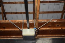
Is this setup going to be a problem? Wasn't quiet sure how to tackle that without room to mount a 4x4 box. I put a 4x2x1-7/8 instead. Without the mud ring the gaps in the sheetrock to gang box is very noticeable.
If this won't work, what are my alternatives?
i have never seen anything like that
X2! That's pretty ugly. (Response to post 43)
From th elooks of things, I'd guess there's a bit-o-romex sticking out of a garage ceiling by a garage door opener.
Get a 4x4 metal box, use a box clamp for the romex in from the ceiling. and come out w/ plain 1/2 EMT fittings where the weird fittings are on the 2x4 box in the pic.
Or, since a garage is almost always accessible, do the wiring more correctly and inconspicuously as usual in a residential setting...


The more-complex, and probably 'right' way to get that out of your way is to get a couple of more pieces of that L Brace (available at Home Depot...near the EMT and strut), or, even better, a couple of pieces of strut (see my recent posts, about mounting the Reconfigurable Tool Rack), about 24" long...
Use those 24" pieces of strut to go the OTHER way on both ends and support the weight of the garage door opener on 4 joists, instead of two, leaving the space between that joist free for the quad box, or whatever you need.
On another note, I don't see any reason the quad box below the ceiling (what you have as a double, metal box now) has to be 'centered' on the quad box below. There are lotsa different knock-outs on those boxes--and as long as the box below the ceiling is securely mounted, I don't see why it has be centered.
M_P
That brace is already bent all over the place. It seems like an after thought. We think the POs of the house did get up into the garage ceiling for some plumbing issues
")
GirlnAgarage I do give you an "A" for creativity on your original configuration.
Stay after it !
 Hitting a hot shower now. My body is unhappy with me standing on a ladder while working overhead.
 The impression I got from reading prior to starting the work was that once I got into any old work I'd have to bring it up to current requirements. Since all outlets in the garage are now required to be GFCI, the outlet I was tapping off did need to be upgraded to GFCI. Also, the outlet was rated at 15A
  After a brief panic attack I took my dial calipers to the bare wire (afraid I'd find they left 14ga in there and stupidly dropped a 20A breaker on the panel). Much to my relief the wire measured out at .080" which is 12ga according to online charts. Still think I had a mini heart attack though

Quick question - I bought a pack of ground wire pigtails (since they came with screws and I needed screws anyway) but I just noticed the wire is 12ga stranded. Can I used 12ga stranded or do I need to go to a solid wire?
I assume they have ends crimped on them anyhow. There is no issue with using stranded wire. These are made stranded to allow for more flex when stuffing everything in the box to put the face on.
Charles
Also, the outlet was rated at 15A


IIRC, now the "neutrals" (white wire in a standard US 120V system) have to be "continuous" and not rely on continuity through a device (outlet, switch, whatever) or 'pass-thru' a device. Thus the neutral wires all get wire-nutted together and pigtails go to the devices (outlet, switch, whatever).
Instead of using the ground pigtails looped the ground wire around the box screw then led it out to the receptacle ground screw. Is that an acceptable method?
Thanks again for the help.Green ticket - outlets done
........................Thats what I do most of the time. Sometimes I combine all the grounds under a greenie wire nut and leave one passing out thru the hole in the greenie.
You can have multiple ground jumpers if needed, from each receptacle to the box. Those holes in the sides of the box, they thread nicely for 10-32. I even found one of these (six in one tapping tool) at the flea market (new) to make it easier.

Charles
Hey Charles, thanks for posting great info; it's been very informative. I have a couple of questions that come to mind. If a GFCI outlet is installed properly, is there really a need to be so stringent on the grounding since GFCI is supposed to protect you anyway? Or is it because in case the GFCI fails, you need ground protection as backup? Also, do you really need to ground each receptacle to the box (i.e. wire attached from the green nut on the receptacle to another green nut on the metal box)? The receptacle is already screwed into the box cover, which activates the ground. I opened up one of the boxes in my garage and found no ground wire (just black and white), yet the ground prong works due to receptacle being screwed into the box. This box was installed by a contractor back in 2003, so was just wondering if NEC code permits this. If not, I'll simply attach some ground wire just to be safe.
Thanks.
BUMP for Charles !
How would the box/conduit be grounded if it is added on the surface of the walls? (assuming it's a two wire system from the panel?).