To avoid these ads, REGISTER NOW!

Engineered a part, can it be fabricated?

FordTruckWench

Well-known member
Joined
Jan 8, 2015
Messages
539
Location
California
Yes, of course, but...

(Oh, the eternal struggle between engineers and fabricators. I'm both in this instance.)

I need to cut double beveled points on 4x4's to use them as diagonal braces. (Think of the difference between a flat roof, shed roof, gable end roof, and hip roof. I need the "gable end" style - except asymmetric.)

My spreadsheet has all the dimensions and angles, and of course can calculate any other needed values. Which numbers are actually useful for cutting the lumber on a compound miter saw?

My thinking: Start with the OverAll Length (OAL) and chop material to this length*. Then measure in from the end to where a heel of a bevel needs to be. Set the saw to the calculated angle. Line the saw blade up to the mark on the edge of the board, and cut. Repeat.

Other possibility: Start by cutting to OAL. Then mark the point on the end (not centered!) where the bevels meet. Cut one bevel. Cut the opposite bevel.

Any other approaches? Any comments that I'll never be able to precisely make the cuts?

Actual numbers for one piece:
OAL: 42 7/64
Angles: 32.75, and 57.25
Heel location from end: 1 19/32 (both sides the same by design)
Tip position from side: 1 1/32 (or 2 15/32 from the other side)
Face widths of the bevels: 2 15/16 and 1 57/64

* Not practical to use one angled cut to make two pieces with that angle: Too many unique pieces, and I'll be pairing dissimilar pieces to best use each piece of lumber.
 
To avoid these ads, REGISTER NOW!

rlitman

Well-known member
Joined
Oct 18, 2010
Messages
24,642
Location
Long Island
Those measurements seem much too precise for lumber.
+- 1/8" is plenty fine for most framing.

It's not common for tape measures to have 32nds, let alone 64ths.
Agreed. Anyway, if you're doing all that math, you may as well just use a ruler that measures in tenths of an inch and estimate the next digit for your pencil line.

Also, cutting to length and then cutting the bevel is a bad idea. If you err on the bevel, you now have scrap. Cut the bevel, and THEN cut to length, and if you mess up on the bevel cut, you can take another stab at it.

edit: I saw another flaw with your plan.
>Then measure in from the end to where a heel of a bevel needs to be. Set the saw to the calculated angle. Line the saw blade up to the mark on the edge of the board, and cut.

Yeah, that's not going to fly. Lumber has radiused corners. If you measure in from the end along the top, you can align your blade with the mark, but the mark will be offset from the edge you're trying to measure along, and if you measure along from the side, you cannot align your blade with the mark.

What I do (when it needs to be this perfect) is measure along the side to make my mark on the correct edge face. Then standing the board up as it would sit on the saw, align a square vertically on the table with this mark, so it runs up the side. Now use an adjustable bevel gauge set to the proper angle (matching the miter saw) on the top of the piece to meet the square. This lets you mark the entire length of the bevel cut on the top, which means that now you can easily meet this mark with your blade, since the blade will be set to the same angle already.

Remember to put your pencil mark on the off-cut side and remove it completely with the blade (yes, pencil lines have a width you need to account for).
 
Last edited:

jack stand

Well-known member
Joined
Feb 29, 2012
Messages
3,346
Location
Lakes Region Maine
Unless this is a personal challenge (that's admirable) could you simply join these 4 points to a central "hub" possibly a piece of schedule 80 pipe?
This sounds interesting, pictures? 👍
 

dutchgray

Well-known member
Joined
Sep 28, 2014
Messages
6,468
Location
Dorset. England.
I would mark up one end fully with a protractor or bevel gauge, cut it, measure and mark the other end the same way and cut to the lines.
 

jack stand

Well-known member
Joined
Feb 29, 2012
Messages
3,346
Location
Lakes Region Maine
Doh, I took it as a metal project after reading "fabricator". My "skimming" skipped right over 4x4 and the rest of the story. 🤪
Mock up the cuts with a sacrificial 2x4 and use the long points to measure and cut to.
 
OP
F

FordTruckWench

Well-known member
Joined
Jan 8, 2015
Messages
539
Location
California
Those measurements seem much too precise for lumber.
+- 1/8" is plenty fine for most framing.

Had to round somewhere: Assume 1/16 markings on a tape measure. Use 1/32nds to mark at or between lines. Use 1/64ths to decide if it is OK if the saw hits long or short.

Might I suggest a good set of carving chisels :unsure:

I guess that is how the Europeans fitted timbers in their timber and stucco buildings...

Unless this is a personal challenge (that's admirable) could you simply join these 4 points to a central "hub" possibly a piece of schedule 80 pipe?

This is diagonal bracing for a shed that will be on stilts due to sloping ground.
 

Sumboodie

Well-known member
Joined
Mar 20, 2021
Messages
10,715
Location
AK
Had to round somewhere: Assume 1/16 markings on a tape measure. Use 1/32nds to mark at or between lines. Use 1/64ths to decide if it is OK if the saw hits long or short.


I guess that is how the Europeans fitted timbers in their timber and stucco buildings...


This is diagonal bracing for a shed that will be on stilts due to sloping ground.

A shed?

Eyeball, Cut with a chainsaw, glue and srew.
Wham bam, thank you ma'am.
 

Garage Junkie

Well-known member
Joined
Jan 2, 2010
Messages
173
Location
Cleveland, OH
You didn't say whether this was diagonal bracing for the legs or for the structure sitting on it, so I'll offer two ideas.

If this is a structure brace within the shed have you considered a shear wall instead? That would provide far greater strength than an individual member or two. Plus, it has the added benefit of allowing you to hang stuff off of it to make the shed more useful. Some folks call this "lining the inside with plywood".

If this is for the legs that the shed will sit on, then I would suggest that some of the best woodworkers out there rarely use a tape measure.... In this case, cut one end with the bevel(s) that the brace needs, then go hold the brace in position and use the structure it will attach to to mark the other end of the 4x4, then go cut on the marks- you can't get a better fit than that.

Also consider your medium. Wood gets shorter and longer depending on the weather. Cutting accuracy is only meaningful on the day you cut it. Every other day it will either be too long or too short..... The allowable tolerances for framing are loose, because the medium demands it. If you frame things too tight, they actually tear themselves apart on their own.
 
Last edited:
To avoid these ads, REGISTER NOW!

speed bump

Well-known member
Joined
May 28, 2008
Messages
6,317
Location
Butte Montana
It's framing, get it close and worse case finesse it with a chisel or a power planer.

With a compound miter saw with the range I would set the bevel and angle for each side and cut it for each side. After I cut that end I would cut to length.
 

MushCreek

Well-known member
Joined
Jan 14, 2015
Messages
9,808
Location
Upstate South Carolina
I'm trying to figure out why all of the oddball dimensions? 30 and 60 degrees won't work? 42" +/- half a hammer handle won't work? Who (other than you) will know of they're all within 1/64", or even 1/4"? I'm a retired tool maker, and as guilty as anyone of overdoing it, but I would just come as close as I reasonably could with a tape measure, and call it good. If I were making a bunch of them, I'd set a stop each step of the way so that they all came out the same. One problem you'll run into is that the 4X4's themselves will vary a lot. I just made a mailbox post, and the 4X4's I bought were 3-1/2" X 3-5/8", and not square.
 

2oolhound

Well-known member
Joined
Dec 18, 2010
Messages
5,918
Location
BC Canada
Also consider your medium. Wood gets shorter and longer depending on the weather. Cutting accuracy is only meaningful on the day you cut it. Every other day it will either be too long or too short..... The allowable tolerances for framing are loose, because the medium demands it. If you frame things too tight, they actually tear themselves apart on their own.
This has not been my finding. I built log buildings for about 10 years using logs sometimes over 50' long. I used spruce, pine and fir. Wood shrinks badly in diameter but not in length.
 

Garage Junkie

Well-known member
Joined
Jan 2, 2010
Messages
173
Location
Cleveland, OH
This has not been my finding. I built log buildings for about 10 years using logs sometimes over 50' long. I used spruce, pine and fir. Wood shrinks badly in diameter but not in length.
True. Fair call-out. Wood only shrinks longitudinally about 0.1-0.2%, which is negligible under normal circumstances. Unless you are building to the nearest 64th......
 
OP
F

FordTruckWench

Well-known member
Joined
Jan 8, 2015
Messages
539
Location
California
I'm trying to figure out why all of the oddball dimensions? 30 and 60 degrees won't work?

Top of one post to the bottom of the next. That way no load is actually going through fasteners (when in compression.)

If I were making a bunch of them, I'd set a stop each step of the way so that they all came out the same.

Only two of each length. So no mass production.

One problem you'll run into is that the 4X4's themselves will vary a lot. I just made a mailbox post, and the 4X4's I bought were 3-1/2" X 3-5/8", and not square.

I can easily update the spreadsheet for the material actually used.

-

Current plan: The OAL is the most important measurement. Off-centeredness of the point is secondary. The angles only need to be close. Where the cuts meet the side doesn't really matter - even though that's what I'm optimizing. Thus, I'll chop cut to OAL, place a tick mark on the now square end, and cut both angles to meet at the tick mark.
 

tarbellb

Well-known member
Joined
Apr 17, 2011
Messages
5,767
Location
Oregon
And this is why we keep the engineers off the job site


"um excuse me, I cant seem to locate the vector point needed on your tape measure"
 
OP
F

FordTruckWench

Well-known member
Joined
Jan 8, 2015
Messages
539
Location
California
This project is moving forward once again. To make the cuts, I measured out the "shoulder" point. Both sides are, by design and calculation, opposite each other. Then I trusted the saw angle(s) to create the end point at the correct location. I drew a line across the "top", and then down each "side". Then sighted along the saw blade at the line on the side.

All four in the picture are different. I had to make 13 total pieces to 6 different specs (i.e. 2 or 3 each). The other end of each board is a single angled cut.

IMG_0694small.jpg
 

RoninB4

Well-known member
Joined
Jul 22, 2020
Messages
3,597
Location
Under My House
Ok I'm curious. What about this is so difficult? I can't get a visual of what you've described, I have limited imagination I suppose. Any paper drawing you make can be photographed and uploaded if opinions are wanted. It need not be exact or to scale but what I see so far in the above photo is done all the time in metal. I'm not diminishing your idea, I'm saying that I don't understand the problem.
 
OP
F

FordTruckWench

Well-known member
Joined
Jan 8, 2015
Messages
539
Location
California
What about this is so difficult?

My first instinct was to measure to locate the end point. This would require two measurements (x and y). If either is off, both cuts are off. I was looking for advice on how to introduce less error. The answer was to measure to the "shoulder". There's only one measurement, and if it is off, then the end is still the right shape, just the wrong length. It also meant the saw could be lined up to a line, not just a single point.

All the pieces are done - and soaked in wood preserver.
 

RoninB4

Well-known member
Joined
Jul 22, 2020
Messages
3,597
Location
Under My House
And in wood, mark it out and cut to the lines.
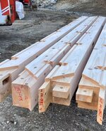
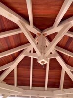
-If the photos show work you did I'm impressed. It reminds me of traditional Japanese joinery and the arched cathedrals in Europe. I've always wanted to attempt something like this but never had the project. Nice work shown in the photos.
 

RoninB4

Well-known member
Joined
Jul 22, 2020
Messages
3,597
Location
Under My House
My first instinct was to measure to locate the end point. This would require two measurements (x and y). If either is off, both cuts are off. I was looking for advice on how to introduce less error. The answer was to measure to the "shoulder". There's only one measurement, and if it is off, then the end is still the right shape, just the wrong length. It also meant the saw could be lined up to a line, not just a single point.

All the pieces are done - and soaked in wood preserver.

-Not to be dismissive of anything you've done but working in X & Y (and Z) is SOP in a Cartesian grid, it's done in metal on a daily basis all around the world. There are ways of checking/measuring intersecting angular planes but you stated that it's already finished and soaking in preservative. Hope it came out the way you wanted it to. Would enjoy seeing it when the project is finished.
 

jar944

Well-known member
Joined
Jul 26, 2010
Messages
5,950
Location
Northern VA
-If the photos show work you did I'm impressed. It reminds me of traditional Japanese joinery and the arched cathedrals in Europe. I've always wanted to attempt something like this but never had the project. Nice work shown in the photos.

Not mine, that's Jeff Kelly's work. He is a timber framer based out of Maine.
 

kwb

Well-known member
Joined
May 1, 2009
Messages
1,776
Location
PNW
The math here isn't hard, but the easy way is to hold the brace up against the face of the post where you want it and simply trace where the vertical and horizontal are. Cut those lines on both end and it should fit just fine and dandy.

Carpenters square or speed square can do this for you as well.
 
To avoid these ads, REGISTER NOW!
Top Bottom