To avoid these ads, REGISTER NOW!

Exhaust fan relay question.

Diesel Dan

Well-known member
Joined
Jul 21, 2013
Messages
2,476
Location
TN
Installing a booster fan in exhaust duct.
Need to control it from 3 separate switches on separate afci/gfi breakers. Looking for a relay, or digital controller, that would have 3 separate inputs/coils for one output, opposite of a 3PST (3-Pole, Single-Throw).
Is there a single, mechanical, relay for this or should I just use 3 cube relays and run the output in parallel?
Quick look at microcontrollers like an Arduino or ESP32 show way more capabilities than I need but still would require a relay to hand the actual fan load.
 
To avoid these ads, REGISTER NOW!

mm08822

Well-known member
Joined
Jan 13, 2012
Messages
6,070
Location
NJ
3 ice cube relays could work as described but all switches (or whatever is driving each relay) would have to be off for the fan to stop. An enclosure would be needed for the relays.

What about 2 3ways and a 4 way arrangement?
 

wssix99

Well-known member
Joined
Mar 2, 2011
Messages
5,166
Location
Chicago, IL
If for a standard HVAC system, there is probably an auxiliary relay/output available on your main board or thermostat to control an auxiliary fan.

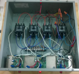
If a custom system, I would use contactors. Here is an arrangement I have with 4 separate switches, each with a contactor switching on two separate circuits at the same time:
1784510312613.png
 

Stuart in MN

Well-known member
Joined
Sep 8, 2005
Messages
23,198
Location
Minneapolis
If you want the fan to be on whenever any of the three switches are closed you don't need a relay with multiple coils, just wire the switches in parallel to a standard relay.
 

Stuart in MN

Well-known member
Joined
Sep 8, 2005
Messages
23,198
Location
Minneapolis
OK, I missed the part about separate breakers. It could be done by using a relay with a DC coil. Put a little 12 volt DC power supply in the box with the relay, then run one AC line to power the fan and use low voltage wiring to the switches.
 
OP
D

Diesel Dan

Well-known member
Joined
Jul 21, 2013
Messages
2,476
Location
TN
3 ice cube relays could work as described but all switches (or whatever is driving each relay) would have to be off for the fan to stop. An enclosure would be needed for the relays.

What about 2 3ways and a 4 way arrangement?
Correct, would be in an enclosure and only off if all rooms are off.
3&4 way, are you referring to wall switches? If so, it's not practical.
If for a standard HVAC system, there is probably an auxiliary relay/output available on your main board or thermostat to control an auxiliary fan.

If a custom system, I would use contactors. Here is an arrangement I have with 4 separate switches, each with a contactor switching on two separate circuits at the same time:
1784510312613.png
Not HVAC, just exhaust fan controlled by wall switches.
 

matt_i

Well-known member
Joined
Mar 14, 2008
Messages
10,758
Location
SE Michigan
We should have a logic/wiring diagram, but if the relay NO contacts are all wired in parallel then each circuit has functionality....BUT if you turn it ON from ckt A you won't be able to go OFF from ckt B (etc).

If you desire functionality where you can go ON from any ckt and OFF from any other ckt then you have to use the relays to setup a pathway identical to a 3way-4way-3way switch. For emulating the 3 way function, a SPDT can be used and for emulating a 4 way you will need DPDT. Of course for simplicity all can be DPDT and you just use 1 pole.
 
OP
D

Diesel Dan

Well-known member
Joined
Jul 21, 2013
Messages
2,476
Location
TN
We should have a logic/wiring diagram, but if the relay NO contacts are all wired in parallel then each circuit has functionality....BUT if you turn it ON from ckt A you won't be able to go OFF from ckt B (etc).

If you desire functionality where you can go ON from any ckt and OFF from any other ckt then you have to use the relays to setup a pathway identical to a 3way-4way-3way switch. For emulating the 3 way function, a SPDT can be used and for emulating a 4 way you will need DPDT. Of course for simplicity all can be DPDT and you just use 1 pole.
On with any switch, off when all switches are off.
 

matt_i

Well-known member
Joined
Mar 14, 2008
Messages
10,758
Location
SE Michigan
Simplest....

3way/4way functionality.....

Then simplified for wiring....

Sorry they are sideways. B1 and B2 just denote different "poles" which share the same coil.
 

Attachments

  • PXL_20260720_132123758.jpg
    PXL_20260720_132123758.jpg
    941.6 KB · Views: 6
  • PXL_20260720_132128696.jpg
    PXL_20260720_132128696.jpg
    980.7 KB · Views: 6
  • PXL_20260720_132133766.jpg
    PXL_20260720_132133766.jpg
    1 MB · Views: 5

PCustoms

Well-known member
Joined
Jul 23, 2011
Messages
23,610
Location
VT
Is there currently three separate fans going into the one duct that will have the booster fan ?

Not sure if this is where you were going, but if so, is there a pressure differential switch that can be used to turn the booster on when there is airflow?
 
Last edited:
OP
D

Diesel Dan

Well-known member
Joined
Jul 21, 2013
Messages
2,476
Location
TN
Is there currently three separate fans going into the one duct that will have the booster fan ?
yes but going with one larger inline fan for quieter operation
Not sure if this is where you were going, but if so, is there a pressure differential switch that can be used to turn the booster on when there is airflow?
Had considered powered/sealed dampers for rooms not in use but that adds more complexity with questionable returns.
how about just putting it on the same circuit? would save a lot of complication
If only that simple.

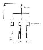
Here is a quick diagram I put together with cube relays, or individual contactors.
This way the AFCI breaker are separate and not causing issues with each other.


switch diagram.png
 
To avoid these ads, REGISTER NOW!

JohnX14

Well-known member
Joined
Jun 2, 2014
Messages
618
Location
Boston 'burbs
Has nothing to do with what I was suggesting
Your suggestion is what I'd have suggested. Airflow sensor that pulls in the booster fan. Regardless of how the upstream fans are wired, airflow will pull on the booster fan. Pretty simple setup. Of course it could be done with relays such that any one fan pulls in the auxiliary fan, but that is far more wiring than your suggestion.
 
OP
D

Diesel Dan

Well-known member
Joined
Jul 21, 2013
Messages
2,476
Location
TN
Your suggestion is what I'd have suggested. Airflow sensor that pulls in the booster fan. Regardless of how the upstream fans are wired, airflow will pull on the booster fan. Pretty simple setup. Of course it could be done with relays such that any one fan pulls in the auxiliary fan, but that is far more wiring than your suggestion.

What air flow sensors are you referring too?
Was looking at a Siemens velocity sensor ($200) but it can't directly control a fan so needs additional controls as well.
 
Last edited:

BillK

Well-known member
Joined
Aug 24, 2006
Messages
9,381
Location
Beautiful Southern Maryland
I didnt think you were supposed to hook multiple fans into one duct ???

Either way if you are doing away with the individual fans then the relays are going to be your only choice. Seems like a wiring nightmare unless all three of the switches are in very close proximity.
 
OP
D

Diesel Dan

Well-known member
Joined
Jul 21, 2013
Messages
2,476
Location
TN
I didnt think you were supposed to hook multiple fans into one duct ???

Either way if you are doing away with the individual fans then the relays are going to be your only choice. Seems like a wiring nightmare unless all three of the switches are in very close proximity.
At this moment there is only the one in-line "booster" fan.
Wiring, the signal wires from the switches to the attic were installed when the house was built. So, it's a non-issue. Just waiting on a decision for control so I can buy appropriate enclosure for hardware. Switches are on different floors, different zones.
 

PCustoms

Well-known member
Joined
Jul 23, 2011
Messages
23,610
Location
VT
At this moment there is only the one in-line "booster" fan.
Wiring, the signal wires from the switches to the attic were installed when the house was built. So, it's a non-issue. Just waiting on a decision for control so I can buy appropriate enclosure for hardware. Switches are on different floors, different zones.
What are the other 3 fans ducted into? Or are you removing 3 fans and using 1?

Can you draw out a diagram of the full duct? There's some advice in this thread that I think you're overlooking
 
OP
D

Diesel Dan

Well-known member
Joined
Jul 21, 2013
Messages
2,476
Location
TN
What are the other 3 fans ducted into? Or are you removing 3 fans and using 1?

Can you draw out a diagram of the full duct? There's some advice in this thread that I think you're overlooking
Pulled the box fans from the enclosures, 3 into 1 duct.
That isn't the concern here. Just trying to iron out basic fan control, no complex smart home gadgets etc.
Unfortunately, this is the internet and the message tone can be taken the wrong way. I try and keep the original message to the basics because if it runs on people gloss over details and things get side tracked.

What do you think I'm overlooking?
 

PCustoms

Well-known member
Joined
Jul 23, 2011
Messages
23,610
Location
VT
Pulled the box fans from the enclosures, 3 into 1 duct.
That isn't the concern here. Just trying to iron out basic fan control, no complex smart home gadgets etc.
Unfortunately, this is the internet and the message tone can be taken the wrong way. I try and keep the original message to the basics because if it runs on people gloss over details and things get side tracked.

What do you think I'm overlooking?

Unfortunately your original message used "booster fan" which implies other fans in the system.

What you're really looking to do is install a single inline fan with 3 inlets controlled by 3 separate controls.

I'll think about this and maybe post back later. Using a simple flow switch (triggered off airflow from fans we now know don't exist) would have been dead simple and required minimal wiring.
 
OP
D

Diesel Dan

Well-known member
Joined
Jul 21, 2013
Messages
2,476
Location
TN
Unfortunately your original message used "booster fan" which implies other fans in the system.

What you're really looking to do is install a single inline fan with 3 inlets controlled by 3 separate controls.

I'll think about this and maybe post back later. Using a simple flow switch (triggered off airflow from fans we now know don't exist) would have been dead simple and required minimal wiring.
Yes, I did use "booster" hoping to simplify things. Had I just said in-line fan then I expected all the duct questions to follow.

3 separate inputs/coils for one output
Exactly what I was looking for.

There is already wiring to the attic from all the switches. I don't know how much simpler wiring can be at this point.
These flow switches, what kind of amp/watt rating do they have? The one I found still required some kind of IO control and/or relay for the load. More hardware, more wires.

Looking on Digi key and supply house for options but there is lots to choose from regarding cube relays and contactors.
 
OP
D

Diesel Dan

Well-known member
Joined
Jul 21, 2013
Messages
2,476
Location
TN
With the Caseta system, were you thinking about the smart outdoor plug being controlled by 3 pico switches to control the fan motor?
 

BillK

Well-known member
Joined
Aug 24, 2006
Messages
9,381
Location
Beautiful Southern Maryland
Your drawing in post #17 is all you need. Flow switches would not be in play, they would only work if you had the individual fans still pushing air. The biggest thing will be finding an appropriate box and three relays. I would not use the "cube" type relays. One more thing to go wrong with a plug in relay. I would use hard wired relays. Something like this but with the correct rating for the load you have :
Click on "google search"

Just to be certain . . . . the wires that are already there are 120V ? And do you have a separate power feed for the fan ?
 

PCustoms

Well-known member
Joined
Jul 23, 2011
Messages
23,610
Location
VT
With the Caseta system, were you thinking about the smart outdoor plug being controlled by 3 pico switches to control the fan motor?

That was my initial thought.

I haven't set one of these up, but knew people here have, and it eliminates additional wiring and relays (that not everyone will be able to service) to have issues with later.
 
OP
D

Diesel Dan

Well-known member
Joined
Jul 21, 2013
Messages
2,476
Location
TN
Your drawing in post #17 is all you need. Flow switches would not be in play, they would only work if you had the individual fans still pushing air. The biggest thing will be finding an appropriate box and three relays. I would not use the "cube" type relays. One more thing to go wrong with a plug in relay. I would use hard wired relays. Something like this but with the correct rating for the load you have :


Just to be certain . . . . the wires that are already there are 120V ? And do you have a separate power feed for the fan ?
Ran 14-2 romex from each location to the attic and yes, power available for the fan.
Cube relays is something a work electrician mentioned, industrial stuff. Regardless if I use those or a standard hardwired relay/contactor I'd purchase a 4th and keep it in/near the enclosure as a spare.
I haven't set one of these up, but knew people here have, and it eliminates additional wiring and relays (that not everyone will be able to service) to have issues with later.
I'd still need the enclosure, cut the prongs off the leads and hardwire in, plus none of the switches would match the rest of the house. If one fails they'd possibly have a harder time finding replacements vs a local electric supply house.

However, thanks for the recommendation as it may come in useful for actual outdoor applications.
 
OP
D

Diesel Dan

Well-known member
Joined
Jul 21, 2013
Messages
2,476
Location
TN
If for a standard HVAC system, there is probably an auxiliary relay/output available on your main board or thermostat to control an auxiliary fan.

If a custom system, I would use contactors. Here is an arrangement I have with 4 separate switches, each with a contactor switching on two separate circuits at the same time:
1784510312613.png
Do you have a PN for those contactors?
 

willf650

Well-known member
Joined
Mar 10, 2010
Messages
931
Look at functional devices. The have RIBs- relay in a box and don’t have a 3 relay version but do have a two relay version as well as the standard siingle relay versions.

They mount on a box knock out and you can wire the contacts in parallel.

Actually they have exactly what your looking for can use 24v coils

If you want all 120v coils you could get this and this.

These will do fractional hp motors but they do make relays with higher ratings if you require it.

RIBs will get you away from making a panel unless that’s what you want.
 
Last edited:
To avoid these ads, REGISTER NOW!
Top Bottom