To avoid these ads, REGISTER NOW!

Exhaust system build w/questions

nonhog

Well-known member
Joined
Nov 6, 2007
Messages
2,451
Location
Arizona (Tucson)
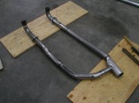
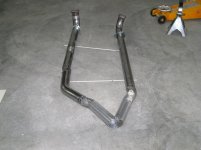
Building an exhaust system for my wifes V8 Volvo project.
Its a 5.0 Ford Explorer (stock) I added block hugger headers after messing with the Mustang shorties. (ruined the shorties:()

So it'll be a 2 into one. system. 2.25 into 3" then down to 2.5
So far I've done well (being my first real system)
I am doing this while the car is on jack stands. So its a lot of up/down
measure/cut/weld over and over. It is what it is. :thumbup:
I'm just tacking it in place (MIG) I'll have an exhaust guy who owes me
finish the welding

Time for my questions:
1) I am thinking I should line up both sides of the head pipes then
tack a couple bars across them to keep them "in place" then pull it down as
a unit to add the 'Y'. Does that sound right. I'm trying to weld as little as possible under the car.

2 I am thinking about making my own 'Y' pipe. (2) 2.25 into 3.
I had a real ugly merge. Cut it off already.:) A co-worker who use to work at an exhaust shop told me to be careful with the 'Y' because if its not smooth it could cause a Pffft (tick?) noise. The only noise I want from this system is from the tailpipe.

3 How crucial is the placement of the ball flange? I will make every effort to be sure the flange is square on the 'ball'
Just curious there, not a problem at this point.

Thoughts/wisdom welcome!
 

Attachments

  • bends BERTONE 001.jpg
    bends BERTONE 001.jpg
    155.2 KB · Views: 169
  • bends%20BERTONE%20005.jpg
    bends%20BERTONE%20005.jpg
    143.8 KB · Views: 240
  • bends%20BERTONE%20002.jpg
    bends%20BERTONE%20002.jpg
    140 KB · Views: 229
  • bends%20BERTONE%20001.jpg
    bends%20BERTONE%20001.jpg
    140.4 KB · Views: 185
  • bends BERTONE 012.jpg
    bends BERTONE 012.jpg
    141.3 KB · Views: 150
  • bends BERTONE 009.jpg
    bends BERTONE 009.jpg
    149.5 KB · Views: 172
To avoid these ads, REGISTER NOW!

ADSR

Well-known member
Joined
Jan 12, 2013
Messages
10,713
You're doing a great job so far. Don't over think it. The ball flange is can be off a mile and still seal. Of course, try your best to get them right. Build the Y pipe. I've built them and have never heard strange noises.

Looks good and am sure it's going to sound awesome!
 

MarkG

Well-known member
Joined
May 23, 2012
Messages
1,219
Location
Elgin, IL
If it were me, I'd do anything I could to avoid teeing straight into that collector at a 90! The closer you can get to going straight out, the better, even any angle would be better than a straight 90.

The way it's arranged now, part of the pulses will be pushing back up the other side against those that are trying to exit. Point a water hose with a nozzle straight at the concrete (at a 90----like your current setup pictured) and pull the trigger and it might help illustrate where I'm coming from---the water goes out in ALL directions when it hits the pavement (the 90). If this was exhaust, it would be hindering the flow from the other bank of cylinders since part of it would be pushing AGAINST the flow. If you angle it and spray, it all goes one way. That's just my first impression, FWIW.

Sounds like a cool project-----I'm going to track down your other threads/pics and read up on it.
 

rsanter

Well-known member
Joined
Dec 22, 2007
Messages
18,558
Location
visalia ca
Looks like a simple system
You need to make the pipes from the 2 sides blend together. Take the one and put a radius bend so they will get next to one another and then take the 3" pipe and oval it to act like a collector.
Why only a single 2.5? Seems like it could be a little small

Bob
 
OP
N

nonhog

Well-known member
Joined
Nov 6, 2007
Messages
2,451
Location
Arizona (Tucson)
You're doing a great job so far. Don't over think it. The ball flange is can be off a mile and still seal. Of course, try your best to get them right. Build the Y pipe. I've built them and have never heard strange noises.

Looks good and am sure it's going to sound awesome!

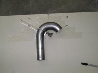
Thanks! Your post got me out in the shop tonight. I started/stopped and
almost gave up but kept going. Got 2 2.25 sticks cut @ 60* and will see how that fits. By then it was late and time to go in. More pics later....
 
OP
N

nonhog

Well-known member
Joined
Nov 6, 2007
Messages
2,451
Location
Arizona (Tucson)
If it were me, I'd do anything I could to avoid teeing straight into that collector at a 90! The closer you can get to going straight out, the better, even any angle would be better than a straight 90.

The way it's arranged now, part of the pulses will be pushing back up the other side against those that are trying to exit. Point a water hose with a nozzle straight at the concrete (at a 90----like your current setup pictured) and pull the trigger and it might help illustrate where I'm coming from---the water goes out in ALL directions when it hits the pavement (the 90). If this was exhaust, it would be hindering the flow from the other bank of cylinders since part of it would be pushing AGAINST the flow. If you angle it and spray, it all goes one way. That's just my first impression, FWIW.

Sounds like a cool project-----I'm going to track down your other threads/pics and read up on it.

Good analogy! Yep that part is already off!
I have no post on the build on this forum. Have a few started.
Here is one.....http://brickspeed.net/forum/showthread.php?tid=1784
 
OP
N

nonhog

Well-known member
Joined
Nov 6, 2007
Messages
2,451
Location
Arizona (Tucson)
Looks like a simple system
You need to make the pipes from the 2 sides blend together. Take the one and put a radius bend so they will get next to one another and then take the 3" pipe and oval it to act like a collector.
Why only a single 2.5? Seems like it could be a little small

Bob

I like your idea but I don't have enough bends left to work it like that. (I think?)
I'm pretty sure 2.5 would be just fine. Its for the Mrs. and HP is of little concern to her.
I have a stick and a half of 3" I might have my exhaust guy bend that up
if he's o.k. with that. Other wise I'll tack my mandrel 2.5 pieces and have him finish welding them.
Reality is I don't know how this will all end till I'm done. :dunno:

If I had a lift this stuff would be fun. :beer:
 

dwp99

Well-known member
Joined
Apr 18, 2012
Messages
167
Location
West Coast of Florida
Looks great, Awfully tight down through the frame. Hope it doesn't hit when the motor flexes in the mounts. Question, fuel injected or carbureted? Reason, If fuel injected I don't see and O2 sensor bungs or cats.
 
OP
N

nonhog

Well-known member
Joined
Nov 6, 2007
Messages
2,451
Location
Arizona (Tucson)
Looks great, Awfully tight down through the frame. Hope it doesn't hit when the motor flexes in the mounts. Question, fuel injected or carbureted? Reason, If fuel injected I don't see and O2 sensor bungs or cats.

Thanks! I will have the guy who will finish welding add bungs for O2.
Its not as tight as it looks. Has at least 3/4" clearance everywhere.
 

Bob Heine

ALLIANCE MEMBER
Joined
Oct 24, 2009
Messages
10,717
Location
Boca Raton, Florida
I can't tell from the under-car picture if you have room but if you want a ready-made (slip-on) Y-connection from your two 2.25" to 3" (or even 2.25" to 2.5") pipes, Jones Exhaust makes them.
jex-u1-1_w_ml.jpg

They designed them to adapt single exhaust to duals so their in/out sizes are reversed. Summit Racing sells them for $15.95 plus shipping:

U6-3 - 3" IN/DUAL 2.25" OUT - FITS 3" PIPE
http://www.summitracing.com/parts/jex-u6-3

U4-3 - 2.50" IN/DUAL 2.25" OUT - FITS 2.50" PIPE
http://www.summitracing.com/parts/jex-u4-3
 
OP
N

nonhog

Well-known member
Joined
Nov 6, 2007
Messages
2,451
Location
Arizona (Tucson)
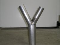
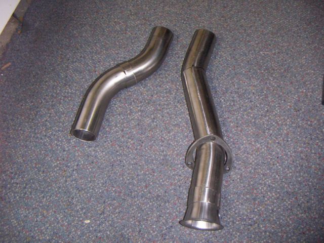
Small progress tonight
Angled the 2.25 pieces then cut off the tip.
Now to make smooth bends tying it all together.
We'll see.

Not the best 'Y' set up but way better than that other thing I made. :D

I know I could buy one but I have some tube and time this weekend.
So if it works great, if not I'll buy one.
 

Attachments

  • bends BERTONE 001.jpg
    bends BERTONE 001.jpg
    140.6 KB · Views: 40
  • bends BERTONE 002.jpg
    bends BERTONE 002.jpg
    143.6 KB · Views: 46
  • bends BERTONE 004.jpg
    bends BERTONE 004.jpg
    149.6 KB · Views: 72
  • bends BERTONE 005.jpg
    bends BERTONE 005.jpg
    144.5 KB · Views: 58

Bob Heine

ALLIANCE MEMBER
Joined
Oct 24, 2009
Messages
10,717
Location
Boca Raton, Florida
Small progress tonight
Angled the 2.25 pieces then cut off the tip.
Now to make smooth bends tying it all together.
We'll see.

Not the best 'Y' set up but way better than that other thing I made. :D

I know I could buy one but I have some tube and time this weekend.
So if it works great, if not I'll buy one.
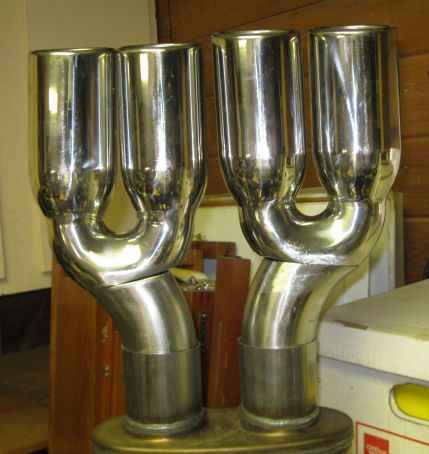
I understand and agree completely. I'm making my own custom exhaust and nobody makes what I'm trying to do (single dual in/out muffler with quad tips). Here's my pre-welded trial fit (before I made the final cuts to line it all up.
FirstMock-up_zpsfe0cf2ab.jpg
 
OP
N

nonhog

Well-known member
Joined
Nov 6, 2007
Messages
2,451
Location
Arizona (Tucson)
I understand and agree completely. I'm making my own custom exhaust and nobody makes what I'm trying to do (single dual in/out muffler with quad tips). Here's my pre-welded trial fit (before I made the final cuts to line it all up.
FirstMock-up_zpsfe0cf2ab.jpg

Dang! That's nice. Here's how my stuff is looking now.
 

Attachments

  • bends BERTONE 006.jpg
    bends BERTONE 006.jpg
    137.1 KB · Views: 65
  • bends BERTONE 005.jpg
    bends BERTONE 005.jpg
    138.6 KB · Views: 72
OP
N

nonhog

Well-known member
Joined
Nov 6, 2007
Messages
2,451
Location
Arizona (Tucson)
That is much better than the first one.:thumbup:

Thanks!

That looks great. Have you thought of using a 3" muffler? It would be a shame to neck it down to a 2.5" from that big opening.

Thanks!
I keep going back and forth. The exhaust expert who I'm working with doesn't do mandrel bends. I suppose its not needed for this horsepower level.
Maybe for clearance sake I'll talk to him about him finishing off the system with 2.75". Still a couple steps away.
 
To avoid these ads, REGISTER NOW!
OP
N

nonhog

Well-known member
Joined
Nov 6, 2007
Messages
2,451
Location
Arizona (Tucson)
Headed to the exhaust shop for welding.
:thumbup:
 

Attachments

  • 3 added.jpg
    3 added.jpg
    36.7 KB · Views: 71
  • waiting welds.jpg
    waiting welds.jpg
    35.5 KB · Views: 81
OP
N

nonhog

Well-known member
Joined
Nov 6, 2007
Messages
2,451
Location
Arizona (Tucson)
Stopped by the exhaust shop last night. Had to confirm the O2 bung location.
They had everything else welded up very nicely from what I saw.

We then discussed muffler, pipe size and muffler location.
All stuff I need to think through as what I had decided in my head has since been mixed up a bit. I was sure that I would neck down from 3" down to 2.5"
and run the muffler transverse in the stock Volvo location.

Mike the owner said I should consider keeping it 3" till after the muffler then run it 2.5. If it has room clearance wise.
Other idea he had was running the muffler before the axle (where Volvo had a resonator) as that would provide better sound than having the muffler further back.

Anybody change there muffler location and found it was better sounding.
Have to use the same design muffler for that test to be of any use.

Thinking....................:headscrat
 

Bob Heine

ALLIANCE MEMBER
Joined
Oct 24, 2009
Messages
10,717
Location
Boca Raton, Florida
If you have a general idea of the size muffler you want, most of the muffler companies have selectors on their websites to help you out. If you have room, Walker's 17809 muffler has a 3" inlet and outlet, aluminized steel construction that Summit Racing and others sell for $26.95. It's a 4"x9" oval case with center inlet, offset outlet and has a 23" case (29" overall). Magnaflow's 11209 is smaller, with a 14" case and center inlet and outlet. It's all stainless steel so it's quite a bit more ($89.71).

Here's a couple of links to the Magnaflow and Walker selectors.

Magnaflow:
http://www.magnaflow.com/02product/02muffler.asp

Walker:
http://www.walkerexhaust.com/catalog/walker-exhaust-systems/universal-muffler-dimension-search
 
OP
N

nonhog

Well-known member
Joined
Nov 6, 2007
Messages
2,451
Location
Arizona (Tucson)
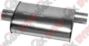
Had a buddy drop off a 3" Dynomax Super Turbo. I'll try it under the car and see if it fits.
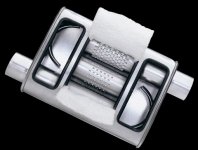
Here is my (new) question. How do the flow directors work with a center/side
style?
All the pics I find are side/side.
The muffler my friend brought is center/side. # 17793.

Wonder if anyone has opened one up or is better at searching Google images
than I.
 

Attachments

  • 17793.jpg
    17793.jpg
    29.7 KB · Views: 9
  • muf_super.jpg
    muf_super.jpg
    50 KB · Views: 14
OP
N

nonhog

Well-known member
Joined
Nov 6, 2007
Messages
2,451
Location
Arizona (Tucson)
I'll second that! Nice job.

Thanks!

Got it welded and bungs added.
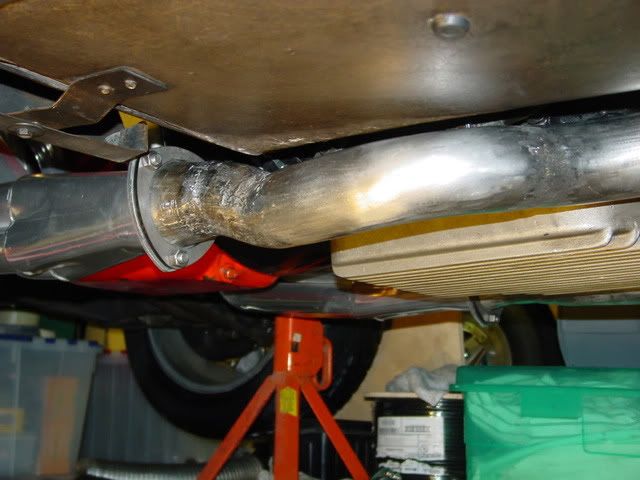
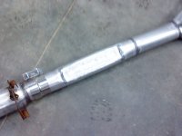
Got a 3" Super Turbo muffler. Going with the muffler in the resonator spot. If its too loud I have plenty of room to add a resonator.
bends BERTONE 001 (3).jpg
Stock resonator vs. Super Turbo
bends%20BERTONE%20001 (2).jpg
 

scratchedup

Well-known member
Joined
Aug 13, 2012
Messages
834
Location
Fayetteville, GA
I saw 3/4" mentioned. I'm doing a similar project and am curious from the old heads how much clearance from the frame/body and tubing parts?

And how often to add hangers?
 
OP
N

nonhog

Well-known member
Joined
Nov 6, 2007
Messages
2,451
Location
Arizona (Tucson)
I saw 3/4" mentioned. I'm doing a similar project and am curious from the old heads how much clearance from the frame/body and tubing parts?

And how often to add hangers?

http://www.jefflilly.com/fabrication/exhaust-system/

Not sure about how often on hangers but be careful not to use the floor pan as it could act as a drum.
I'll put hangers off the frame rails and let the exhaust guy do the rest.
Seems to me, most systems just have them at the muffler(s) then again at the tail pipes. But there is probably a rule of thumb. :dunno:
 
OP
N

nonhog

Well-known member
Joined
Nov 6, 2007
Messages
2,451
Location
Arizona (Tucson)
Re: Exhaust system build w/ *NEW* question

At a snails pace but still at it. :thumbup:
Coming up against a clearance issue where I want to run the 3" pipe straight but the floor pan drops down at passengers feet to where the pipe doesn't have enough wiggle room.

3" single is enough, more than enough so don't bother talking about flow.
It'll be fine.

So do I just pound a flat area into the straight section? Or cut out a bit
and weld in a flat spot. That would possibly look better. Even though nobody could see it. It also adds the risk for leaks. Lots of welding.
Thought about using mandrel bends and lowering the pipe where needed but prefer not to have the exhaust the low point on the car. As much as I can help it.
I really don't want to slow down and spend money on a oval pipe transition but may if all else fails.

Thoughts?
 

Bob Heine

ALLIANCE MEMBER
Joined
Oct 24, 2009
Messages
10,717
Location
Boca Raton, Florida
Re: Exhaust system build w/ *NEW* question

At a snails pace but still at it. :thumbup:
Coming up against a clearance issue where I want to run the 3" pipe straight but the floor pan drops down at passengers feet to where the pipe doesn't have enough wiggle room.

So do I just pound a flat area into the straight section? Or cut out a bit
and weld in a flat spot. That would possibly look better. Even though nobody could see it. It also adds the risk for leaks. Lots of welding.
Thought about using mandrel bends and lowering the pipe where needed but prefer not to have the exhaust the low point on the car. As much as I can help it.
I really don't want to slow down and spend money on a oval pipe transition but may if all else fails.

Thoughts?

I think pounding the flat area is probably the simplest solution. If you are going to weld something in or have somebody weld something in, the flat spot is probably the most work for the least benefit. The oval pipe is the most elegant solution but may be overkill.

Instead of mandrel bends, have you thought about making a couple of pie cuts to get the jog you need. Something like the one on the right?
StainlessPipes_zpsd3faed04.jpg


You're right about the amount of welding but I ended up making pie cuts and then inserting a couple of short pieces of curved pipe from a left-over curved piece.
065.jpg
 

rsanter

Well-known member
Joined
Dec 22, 2007
Messages
18,558
Location
visalia ca
If the 3" is plenty big for the flows you want, then a little hammering to flatten the needed area won't really hurt you. Make as gentle of a transition as you can.
In fact you could clamp the whole section of tube to 'oval' the section as an option verses flattening and again you should still be fine

Bob
 
OP
N

nonhog

Well-known member
Joined
Nov 6, 2007
Messages
2,451
Location
Arizona (Tucson)
Flattened, welded and I have my 3/4" clearance. :rocker:

Now for the tailpipe. (part 2)
 

Attachments

  • BASHED.jpg
    BASHED.jpg
    72.6 KB · Views: 24
  • exhaust%2010%2013%20004.jpg
    exhaust%2010%2013%20004.jpg
    45.2 KB · Views: 17
To avoid these ads, REGISTER NOW!
Top Bottom