To avoid these ads, REGISTER NOW!

f150skidoo Pusher Box Build

f150skidoo

Well-known member
Joined
Dec 29, 2012
Messages
1,206
Location
Ontario, Canada
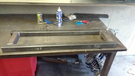
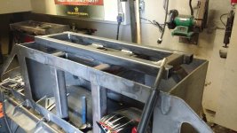
So I'm in a need of a pusher box blade for plowing snow this coming winter for commercial parking lots. I thought about purchasing a pre-manufactured box but whats the fun in that. This box blade will have a steel cutting edge with a spring trip mechanism, and the SSQA (skid steer quick attach) plate will float independently from the blade I know its early to think about winter but I want to build this right the first time instead of rushing the build to get it done because theirs snow in the forecast.

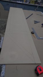
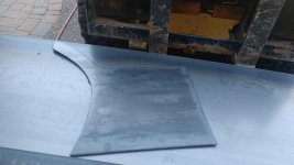
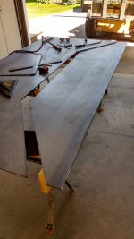
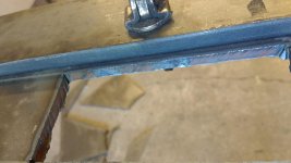
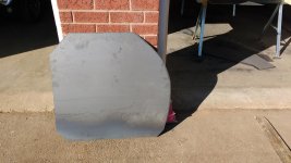
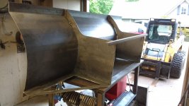
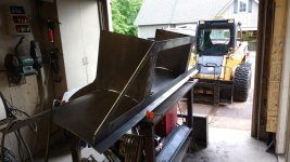
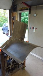
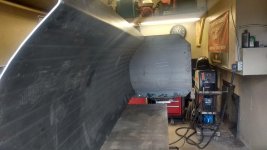
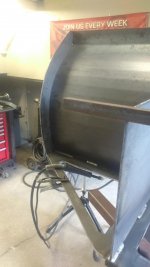
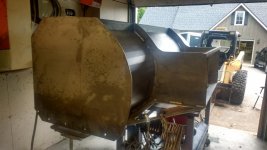
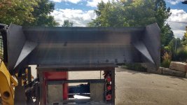
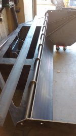
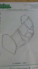
Normally when I do a build thread like my 5'x8' dump trailer or stump grapple I built it entirely off the top of my head. but since the blade is all curves and some parts of the build I'm outsourcing I had to do a drawing and make templates to make sure everything will work. I had a local fab shop bump bend 3/16" steel to the shape of the moldboard.
 

Attachments

  • IMG_20160829_172039517.jpg
    IMG_20160829_172039517.jpg
    147.8 KB · Views: 345
  • IMG_20160829_172022429_HDR.jpg
    IMG_20160829_172022429_HDR.jpg
    140.3 KB · Views: 379
  • IMG_20160902_162114590.jpg
    IMG_20160902_162114590.jpg
    147 KB · Views: 412
  • IMG_20160902_162349679.jpg
    IMG_20160902_162349679.jpg
    134.4 KB · Views: 283
  • IMG_20160902_182759697.jpg
    IMG_20160902_182759697.jpg
    134.3 KB · Views: 271
To avoid these ads, REGISTER NOW!
OP
F

f150skidoo

Well-known member
Joined
Dec 29, 2012
Messages
1,206
Location
Ontario, Canada
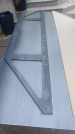
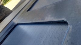
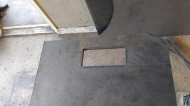
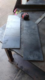
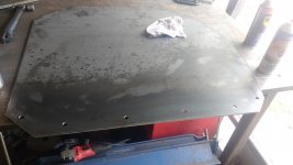
I picked up 2 4'x8' sheets of 1/4" plate to plasma cut all the parts from. First part was to make the lower gussets that spans the full 8' of the blade, this part alone has 27' of cuts done with the plasma. All the inside radius corners I used the mag drill with a 1.5" annular cutter then just used a straight edge to connect the dots. Next part to cut was center moldboard ribs that connect to the Q/A plate (quick attach). I still need to chip off the dross then run the flap disk to clean up all the edges.
 

Attachments

  • IMG_20160903_162841814.jpg
    IMG_20160903_162841814.jpg
    138.1 KB · Views: 173
  • IMG_20160903_162419902.jpg
    IMG_20160903_162419902.jpg
    144.6 KB · Views: 181
  • IMG_20160903_154111232.jpg
    IMG_20160903_154111232.jpg
    141.6 KB · Views: 184
  • IMG_20160903_154058319_HDR.jpg
    IMG_20160903_154058319_HDR.jpg
    131.3 KB · Views: 182
  • IMG_20160903_130510939.jpg
    IMG_20160903_130510939.jpg
    145.5 KB · Views: 214
  • IMG_20160903_130255954_HDR.jpg
    IMG_20160903_130255954_HDR.jpg
    145.5 KB · Views: 206
Last edited:

LXCam

ALLIANCE MEMBER
Joined
Apr 23, 2013
Messages
19,175
Location
AZ
Just getting in line for another kickass project. Looking forwards to it coming together bud.
 

WhiffySpark

Well-known member
Joined
Oct 22, 2009
Messages
6,252
How far is the plate going to be from the moldboard? Just curious we use protech and
 
OP
F

f150skidoo

Well-known member
Joined
Dec 29, 2012
Messages
1,206
Location
Ontario, Canada
So lots more plasma cutting today, didn't take as many pics as before. Finished cutting the last rib then plasma cut the two 36"x36" side plates. Next was to cut the parts for the Q/A plate like the end caps for the tube, also cut out the plate for the part that pins on to the skid steer.
 

Attachments

  • IMG_20160904_164931228.jpg
    IMG_20160904_164931228.jpg
    145.3 KB · Views: 119
  • IMG_20160904_163912719.jpg
    IMG_20160904_163912719.jpg
    146 KB · Views: 122
  • IMG_20160904_160451882.jpg
    IMG_20160904_160451882.jpg
    148.2 KB · Views: 124
  • IMG_20160904_160434535.jpg
    IMG_20160904_160434535.jpg
    146.4 KB · Views: 122
  • IMG_20160904_094955876.jpg
    IMG_20160904_094955876.jpg
    148.3 KB · Views: 129
  • IMG_20160904_091452134.jpg
    IMG_20160904_091452134.jpg
    151 KB · Views: 122
OP
F

f150skidoo

Well-known member
Joined
Dec 29, 2012
Messages
1,206
Location
Ontario, Canada
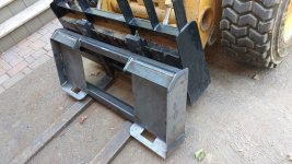
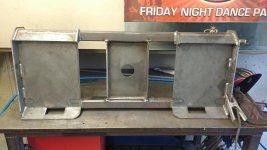
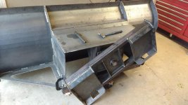
So I fabricated the quick attach mount today which will float independently from the blade. I bent the 1/4" plate paws on my press brake Then tacked up the plate for a test fit which was a flawless fit, next was to weld everything out. After the Q/A plate was done I spend a couple of hours with a flap disk on the grinder to clean up the plasma cut edges, didn't take any pics of that since it would be boring.
 

Attachments

  • IMG_20160905_163736921.jpg
    IMG_20160905_163736921.jpg
    149.9 KB · Views: 284
  • IMG_20160905_133721674.jpg
    IMG_20160905_133721674.jpg
    147.5 KB · Views: 234
  • IMG_20160905_124805859.jpg
    IMG_20160905_124805859.jpg
    146.6 KB · Views: 219
  • IMG_20160905_105620373.jpg
    IMG_20160905_105620373.jpg
    145.3 KB · Views: 209
  • IMG_20160905_090322457_HDR.jpg
    IMG_20160905_090322457_HDR.jpg
    147.7 KB · Views: 198
OP
F

f150skidoo

Well-known member
Joined
Dec 29, 2012
Messages
1,206
Location
Ontario, Canada
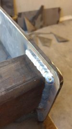
So today was a picture heavy day. First thing was to tack up the middle supporting ribs then the bottom skeleton gusset. Since the blade was in the flat position it was a opportune time to weld it out.
 

Attachments

  • IMG_20160910_133155770.jpg
    IMG_20160910_133155770.jpg
    139.9 KB · Views: 203
  • IMG_20160910_105528608.jpg
    IMG_20160910_105528608.jpg
    144.4 KB · Views: 218
  • IMG_20160910_091957339.jpg
    IMG_20160910_091957339.jpg
    148.2 KB · Views: 233
  • IMG_20160910_091938175.jpg
    IMG_20160910_091938175.jpg
    150.4 KB · Views: 193
  • IMG_20160910_084254746.jpg
    IMG_20160910_084254746.jpg
    145.9 KB · Views: 205
OP
F

f150skidoo

Well-known member
Joined
Dec 29, 2012
Messages
1,206
Location
Ontario, Canada
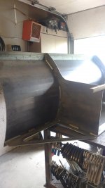
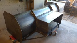
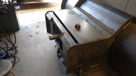
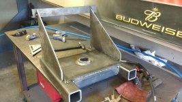
After welding out the ribs to the moldboard i had to take the blade out of the shop to work on the side plates. The only problem was the blade is wider then the garage door, but with a little maneuvering it got out. On the side plates I had to use one of my favourite tools to drill six 9/16" holes for mounting the adjustable skid shoes. At the end of the day I tacked on the first side plate to the moldboard. positioning the side plates to where I want is kind of a PITA since they weigh 80lbs each.
 

Attachments

  • IMG_20160910_162009137_HDR.jpg
    IMG_20160910_162009137_HDR.jpg
    144.4 KB · Views: 211
  • IMG_20160910_161643654.jpg
    IMG_20160910_161643654.jpg
    138.9 KB · Views: 196
  • IMG_20160910_161628808_HDR.jpg
    IMG_20160910_161628808_HDR.jpg
    141.2 KB · Views: 208
  • IMG_20160910_144749169.jpg
    IMG_20160910_144749169.jpg
    137.4 KB · Views: 179
  • IMG_20160910_143833280.jpg
    IMG_20160910_143833280.jpg
    146.8 KB · Views: 200
  • IMG_20160910_134003081.jpg
    IMG_20160910_134003081.jpg
    149.8 KB · Views: 224
  • IMG_20160910_133945646_HDR.jpg
    IMG_20160910_133945646_HDR.jpg
    151.9 KB · Views: 202

WhiffySpark

Well-known member
Joined
Oct 22, 2009
Messages
6,252
Looks pretty good. You may want to add some square tubing in the middle section for bracing. Are you going rubber or steel edge?

I'm not trying to pick on your design just some suggestions. I've been doing snow since I started driving and before that my family took care of the Air Force base where Air Force one is.

One of our sites has 2 18 foot push boxes and a 20 ft plow. Awesome to see lol. They stack snow up and then we use rock trucks to dump it on site.
 
OP
F

f150skidoo

Well-known member
Joined
Dec 29, 2012
Messages
1,206
Location
Ontario, Canada
For the cutting edge I'm doing steel with a trip edge. In the middle section I'm going to add a piece of plate on the top as a step for getting into the machine. Then their will be a X brace in the middle for my lateral float mechanism. Their will also be big gussets between the mold board and side plates.
 

WhiffySpark

Well-known member
Joined
Oct 22, 2009
Messages
6,252
All of ours are rubber. We've even started using rubber blades on the plow trucks as well. They seem to clean okay we may use a little more salt, but less damage. We have one site that is littered with man covers and they would break at least one edge a storm.

I would like to try an artic sectional one day
 

MichaelBikel

Well-known member
Joined
Apr 11, 2015
Messages
379
Location
CT
This is one of the cooler things I have seen on this site, that's some serious ingenuity right there!
 
OP
F

f150skidoo

Well-known member
Joined
Dec 29, 2012
Messages
1,206
Location
Ontario, Canada
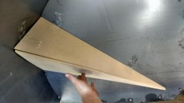
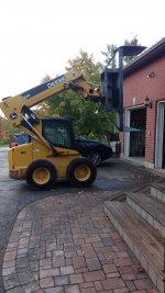
After I got the side plates tacked on it was time to fabricate the gussets. Used some MDF for my templates, which was a good thing since it took me 3 tries to get the angles right. I wanted to take the pusher outside to double check that the gussets were identical. So it was easier to lift the table out side with the blade on it, combined weight probably is around 2000 lbs. I had to cut up a bunch of pieces of plate for the step so my Miller plasma is certainly a priceless tool.
 

Attachments

  • IMG_20160911_165323973.jpg
    IMG_20160911_165323973.jpg
    142.8 KB · Views: 256
  • IMG_20160911_135232640_HDR.jpg
    IMG_20160911_135232640_HDR.jpg
    152.6 KB · Views: 209
  • IMG_20160911_113433366_HDR.jpg
    IMG_20160911_113433366_HDR.jpg
    150.4 KB · Views: 221
  • IMG_20160911_113417668_HDR.jpg
    IMG_20160911_113417668_HDR.jpg
    150.5 KB · Views: 280
  • IMG_20160911_101958000.jpg
    IMG_20160911_101958000.jpg
    140.2 KB · Views: 214
  • IMG_20160911_092323038_HDR.jpg
    IMG_20160911_092323038_HDR.jpg
    146.5 KB · Views: 196

LXCam

ALLIANCE MEMBER
Joined
Apr 23, 2013
Messages
19,175
Location
AZ
Damn, that's a **** load of steel right there. Excellent job as always bud.
 

bimmer1980

Well-known member
Joined
Feb 5, 2009
Messages
2,104
Location
York, PA
I've been following this build with interest! Nice work as always.

I'm thinking about a modification to my skid steer bucket for the small amount of snow work that I do. For those that are using rubber for the cutting edge, where do you buy it, and how big is a typical rubber cutting edge?

I will be curious to see how this works for you this winter. We're looking for some action shots!

I did see a youtube video this weekend of a snow pusher that was hydraulic angle change and had hydraulic side wings. Pretty neat...
FYI on some ideas......
 
OP
F

f150skidoo

Well-known member
Joined
Dec 29, 2012
Messages
1,206
Location
Ontario, Canada
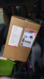
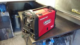
Little update...................... I bought a new welder, Its a Lincoln 210 MP. The new welder is definitely a more powerful welder then the old Hobart Handler 190. Its nice to have a extra 30 amps and a lot more duty cycle room.
 

Attachments

  • IMG_20160915_173052890.jpg
    IMG_20160915_173052890.jpg
    142.7 KB · Views: 68
  • IMG_20160915_185647772.jpg
    IMG_20160915_185647772.jpg
    147.9 KB · Views: 118
OP
F

f150skidoo

Well-known member
Joined
Dec 29, 2012
Messages
1,206
Location
Ontario, Canada
I finally have had a weekend to do some more work to the pusher box. My 9 day old Lincoln decided to stop working, so I'm not a very happy person right now. Monday morning I'm going to return this ************* and buy something different.

Sent from my MotoG3 using Tapatalk
 

readhead

Well-known member
Joined
Dec 8, 2012
Messages
6,187
Location
Durango, Co.
Top notch work as usual. You're wasting your time on bricks and blocks. But I'm guessing you're pretty good at that also.
 
To avoid these ads, REGISTER NOW!

C_F

ALLIANCE MEMBER
Joined
Jan 21, 2005
Messages
9,675
Location
Utah...SNOW BLOWS!
No idea how I missed this thread until now, but I'm sure liking your project!

BTW, do ALL your metal projects have a minimum weight of a ton? :D
 
OP
F

f150skidoo

Well-known member
Joined
Dec 29, 2012
Messages
1,206
Location
Ontario, Canada
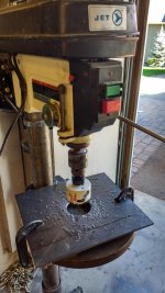
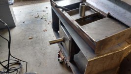
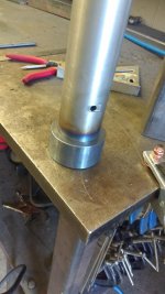
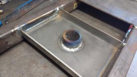
I'm definitely having having one of those weekends. First thing was the welder not working, So I went over to my brothers property to clear some trees and I blew a hydraulic line on my grapple bucket. Now I couldn't do much but fabricate parts that don't require a welder which isn't very much. I started to tackle the pivoting mechanism, the weld in tube is 3" 3/8" wall DOM with a 2.25" pin that was turned down to fit the tubing's ID. Next was to make the pivoting mount on the Q/A part, I drilled a 3" hole in the 1/4" plate with the trusty drill press then bent the plate in the press brake.
 

Attachments

  • IMG_20160925_125638119.jpg
    IMG_20160925_125638119.jpg
    146.2 KB · Views: 117
  • IMG_20160925_114756104_HDR.jpg
    IMG_20160925_114756104_HDR.jpg
    150.9 KB · Views: 131
  • IMG_20160923_164839425.jpg
    IMG_20160923_164839425.jpg
    143.6 KB · Views: 123
OP
F

f150skidoo

Well-known member
Joined
Dec 29, 2012
Messages
1,206
Location
Ontario, Canada
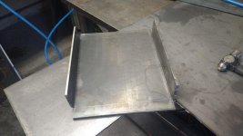
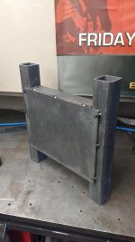
So I got my welder issued resolved, They gave me a new one. Since today was a rain day I was able to get some welding done. I started to tackle the pivoting mounts for the blades float. The two vertical tubes are 2.5" .25" wall tube and I bent some plate to box in the middle section for the DOM tube support.
 

Attachments

  • IMG_20160926_103930714.jpg
    IMG_20160926_103930714.jpg
    143.1 KB · Views: 70
  • IMG_20160926_104919217.jpg
    IMG_20160926_104919217.jpg
    144.1 KB · Views: 70
  • IMG_20160926_111615323.jpg
    IMG_20160926_111615323.jpg
    146.8 KB · Views: 80
  • IMG_20160926_112216553.jpg
    IMG_20160926_112216553.jpg
    146.5 KB · Views: 77
  • IMG_20160926_154930401_HDR.jpg
    IMG_20160926_154930401_HDR.jpg
    145.9 KB · Views: 98
OP
F

f150skidoo

Well-known member
Joined
Dec 29, 2012
Messages
1,206
Location
Ontario, Canada
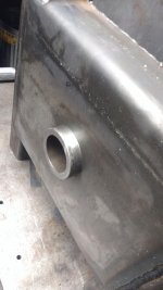
I also welded in the pivot support that I bent up yesterday on the Q/A plate. Once that was complete I was able to weld in the DOM sleeve.
 

Attachments

  • IMG_20160926_171114370.jpg
    IMG_20160926_171114370.jpg
    143 KB · Views: 97
  • IMG_20160926_170944047.jpg
    IMG_20160926_170944047.jpg
    146.7 KB · Views: 90
  • IMG_20160926_165723234.jpg
    IMG_20160926_165723234.jpg
    142.5 KB · Views: 83
  • IMG_20160926_143104053.jpg
    IMG_20160926_143104053.jpg
    147.1 KB · Views: 78
  • IMG_20160926_143528456.jpg
    IMG_20160926_143528456.jpg
    146.8 KB · Views: 82
OP
F

f150skidoo

Well-known member
Joined
Dec 29, 2012
Messages
1,206
Location
Ontario, Canada
I had some more time today, So I was worried if I curled the cylinders to put down pressure on the blade I would bend the lower skeleton frame were it mounts to the H frame pivot mount. I put two large gussets to tie the H frame to the top plate. The main pivot pin will have a 1/2" bolt on the one end and welded collar on the other to retain the pin. I welded a piece of the 3" DOM to the pin with a little pre-heat and 3 passes it was nice to see I got the 2.25" pin blue hot. The pin is also drilled/cross drilled for greasing. I test fitted the Q/A plate to make sure everything fits the way I wanted before I weld anything out. I'm going to plate both side of the H frame to stiffen up that area. Also the stops for the float are going to be the last thing I weld on so I can rotate the blade 360 degrees for positioning.
 

Attachments

  • IMG_20160927_150019951.jpg
    IMG_20160927_150019951.jpg
    144.6 KB · Views: 120
  • IMG_20160927_144706314_HDR.jpg
    IMG_20160927_144706314_HDR.jpg
    146.5 KB · Views: 112
  • IMG_20160927_135752140.jpg
    IMG_20160927_135752140.jpg
    146.1 KB · Views: 110
  • IMG_20160927_131623950_HDR.jpg
    IMG_20160927_131623950_HDR.jpg
    135.6 KB · Views: 124
  • IMG_20160927_111819689.jpg
    IMG_20160927_111819689.jpg
    144 KB · Views: 109
  • IMG_20160927_100310466.jpg
    IMG_20160927_100310466.jpg
    141.4 KB · Views: 119
  • IMG_20160927_092956357.jpg
    IMG_20160927_092956357.jpg
    148.7 KB · Views: 112
OP
F

f150skidoo

Well-known member
Joined
Dec 29, 2012
Messages
1,206
Location
Ontario, Canada
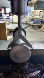
Well this week seems to be making up for the lack of rain we had all summer long. Didn't get a whole lot completed this afternoon but did get the pivot completed. Fist was to weld in the DOM tube into the Q/A plate. Next was to cut down the pivot pin and drill a 1/2" hole for the retaining bolt. As many of you know cross drilling round objects can be a PITA. This inexpensive USA made center finder tool made drilling the DOM tube & pin accurately a breeze, the bolt fit perfectly in the holes.
 

Attachments

  • IMG_20160929_162824771.jpg
    IMG_20160929_162824771.jpg
    147.3 KB · Views: 147
  • IMG_20160929_154424349.jpg
    IMG_20160929_154424349.jpg
    145 KB · Views: 113
  • IMG_20160929_153346981.jpg
    IMG_20160929_153346981.jpg
    146.8 KB · Views: 108
  • IMG_20160929_150935353_HDR.jpg
    IMG_20160929_150935353_HDR.jpg
    140.4 KB · Views: 177
  • IMG_20160929_141748104.jpg
    IMG_20160929_141748104.jpg
    145.1 KB · Views: 98

C_F

ALLIANCE MEMBER
Joined
Jan 21, 2005
Messages
9,675
Location
Utah...SNOW BLOWS!
I'm not sure I understand how the centering tool works. I mean, I can see how it would find center, but where does the drill bit work into the equation?

Your project sure does look stout as hell, nice work!:thumbup:
 

Fcvapor05

Well-known member
Joined
May 4, 2014
Messages
1,079
I'm not sure I understand how the centering tool works. I mean, I can see how it would find center, but where does the drill bit work into the equation?

Your project sure does look stout as hell, nice work!:thumbup:

You set up your cut with the tool, then clamp your workpiece in place and replace the tool with a bit and cut away.
 
OP
F

f150skidoo

Well-known member
Joined
Dec 29, 2012
Messages
1,206
Location
Ontario, Canada
So I finally had a long weekend of more progress. It was certainly nice to be able lift the blade up and rotate it to weld in the flat position at a nice comfortable work height.
 

Attachments

  • IMG_20161008_082226719.jpg
    IMG_20161008_082226719.jpg
    150.2 KB · Views: 147
  • IMG_20161008_134041458.jpg
    IMG_20161008_134041458.jpg
    148.5 KB · Views: 122
  • IMG_20161008_134053869.jpg
    IMG_20161008_134053869.jpg
    134.4 KB · Views: 124
  • IMG_20161008_134237927.jpg
    IMG_20161008_134237927.jpg
    151.4 KB · Views: 114
OP
F

f150skidoo

Well-known member
Joined
Dec 29, 2012
Messages
1,206
Location
Ontario, Canada
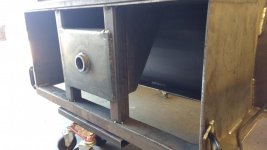
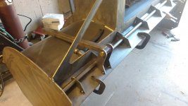
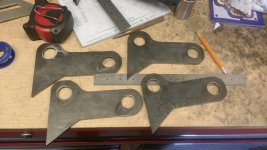
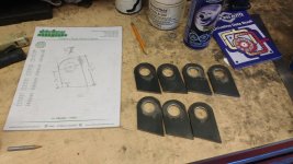
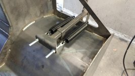
Next part was to tackle the trip mechanism It took a lot of time to make all the brackets (didn't take a pic of all of them). The way it works is when the cutting edge hits a object the blade folds back. But the 4 brackets with 2 holes push a piece of tube upwards which holds the 2 springs per side.
 

Attachments

  • IMG_20161010_155420162.jpg
    IMG_20161010_155420162.jpg
    145.8 KB · Views: 155
  • IMG_20161010_143636877.jpg
    IMG_20161010_143636877.jpg
    145.2 KB · Views: 115
  • IMG_20161010_143505617_HDR.jpg
    IMG_20161010_143505617_HDR.jpg
    150.4 KB · Views: 139
  • IMG_20161010_134346833.jpg
    IMG_20161010_134346833.jpg
    148.7 KB · Views: 108
  • IMG_20161009_153909655.jpg
    IMG_20161009_153909655.jpg
    143.7 KB · Views: 111
  • IMG_20161009_153504438.jpg
    IMG_20161009_153504438.jpg
    146.6 KB · Views: 105

C_F

ALLIANCE MEMBER
Joined
Jan 21, 2005
Messages
9,675
Location
Utah...SNOW BLOWS!
Look again its in a milling vise.

Sure enough. I failed to open the photo to the largest setting initially. I guess it was the straight on photo angle that got me. But it's clear to me now.:thumbup:

I like your trip mechanism design, looks like it will work perfectly.
 
OP
F

f150skidoo

Well-known member
Joined
Dec 29, 2012
Messages
1,206
Location
Ontario, Canada
Bunch more progress this weekend picked up the final little bit of material for the blade and the 5/8"x6" cutting edge. First thing was to finish welding out the trip edge part. Next was to fabricate the sprung portion on the trip mechanism. The guide for the push rod is just 2" 3/16" wall tube. The bracket for the tensioner bolts is just 1/4" plate that's been bent up and welded too the 1.5" push rods tube. To test the trip edge I clamped two 32" long 3/4" pipe clamps to the edge and was barely able to get to trip. But the little bit it did move it snapped back to close with a lot of force, and that's only with 2 of the 4 springs that weren't tensioned properly either.
 

Attachments

  • IMG_20161016_090233446.jpg
    IMG_20161016_090233446.jpg
    145 KB · Views: 116
  • IMG_20161015_161959820.jpg
    IMG_20161015_161959820.jpg
    148.7 KB · Views: 87
  • IMG_20161015_150000571.jpg
    IMG_20161015_150000571.jpg
    145.7 KB · Views: 99
  • IMG_20161015_145709155_HDR.jpg
    IMG_20161015_145709155_HDR.jpg
    144.1 KB · Views: 87
  • IMG_20161013_164000695_HDR.jpg
    IMG_20161013_164000695_HDR.jpg
    152.4 KB · Views: 96
Last edited:
OP
F

f150skidoo

Well-known member
Joined
Dec 29, 2012
Messages
1,206
Location
Ontario, Canada
Next was to fabricate the lateral float stops, The stops are made of 2" .188" tube that will hit the tube of the Q/A plate and limit the blades float. The blade will have 4" of vertical travel over the entire 8' blade width. On the Q/A plate I welded on some 2" tube that will rube against the float limiter frame to help reduce the stress on the center pin.
 

Attachments

  • IMG_20161016_112026726.jpg
    IMG_20161016_112026726.jpg
    144.6 KB · Views: 74
  • IMG_20161016_112057084_HDR.jpg
    IMG_20161016_112057084_HDR.jpg
    144.1 KB · Views: 77
  • IMG_20161016_165639432.jpg
    IMG_20161016_165639432.jpg
    147.2 KB · Views: 96
  • IMG_20161016_152102716.jpg
    IMG_20161016_152102716.jpg
    140.6 KB · Views: 72
To avoid these ads, REGISTER NOW!
Top Bottom