To avoid these ads, REGISTER NOW!

Gantry crane build-planning phase

930dreamer

Super Moderator
Staff member
Joined
Oct 7, 2009
Messages
22,981
Location
Amarillo,TX and Stinnett,TX
Hello GJ,
I'm looking at building a rolling gantry crane/hoist and I just watched a build from Tools4Machines where they drilled through the I-beam. Would it be any better/ worse to weld a plate to the I-beam and side A-frame and bolt together?
 
To avoid these ads, REGISTER NOW!

RPH

Well-known member
Joined
Dec 17, 2006
Messages
4,190
Location
Michigan Thumb
Take a look at the overhead bridge cranes attach the rail supports in iron buildings. A stub of I beam welded to the vertical beam to support the main beam that carries the rails. If the plate is thick enough and has enough linear inches of good weld you should be fine. But this is is totally dependent upon materials and skill of the welder.
 

Riggerson

Active member
Joined
Dec 8, 2018
Messages
44
Location
Atlanta
More detail would be helpful. Thickness of plates/joint design/weld settings/etc. But to answer your question as long as you take care in the previous mentioned variables I don't see a problem. How much weight are you picking up?
 

mikegt4

Well-known member
Joined
Sep 12, 2005
Messages
3,277
Location
sw ohio
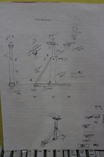
I used a nice gantry while on a temporary assignment at an offsite location for work. I quickly jotted down some dimensions just in case I wanted to build one myself. It has been almost 20 years so I can't go back and check anything (I am retired anyway) but here is the page that I wrote back then. There was a 18"x9"x1/2" plate on top of the vertical column that the I beam sat on. There was a 3-1/2" plate on each side of the I beam clamping it to the large plate. I think that the purpose of this arrangement was to allow the width of the gantry to be adjusted as needed or disassembled although neither would be an easy job. We used it to move production machinery around. For what it is worth you might get some ideas.
 

Attachments

  • gantry crane.jpg
    gantry crane.jpg
    63.9 KB · Views: 195

matt_i

Well-known member
Joined
Mar 14, 2008
Messages
10,741
Location
SE Michigan
This is how I made my gantry.....so it can be taken apart. Bevel washers needed to accommodate the tapered flange of the I-beam (S-shape). I think W-shapes have different tapers...shallow to none.

gantry_hoist_02.jpg


I built it specifically to straddle that bench...15 years later its still parked there in a different shop and comes out occasionally.

gantry_hoist_01.jpg
 

fiftyv8

Well-known member
Joined
Dec 29, 2018
Messages
237
Location
Perth
matt_i, that sure looks to be a very sturdy setup and great that it can be dis-assembled if required.

Good work.
 

RPH

Well-known member
Joined
Dec 17, 2006
Messages
4,190
Location
Michigan Thumb
Ok, guys. Reading comprehension skills. These are nice units shown but he wants his to pivot off a post traveling in the arc. Attaching to the post is today’s question. Feasibility, materials, and methods are being looked at.
 

BD1

Well-known member
Joined
Mar 18, 2007
Messages
4,602
Location
north side
You may consider using a large top plate that extends beyond the beam width with holes and ''U" bolt the beam to the plate. This would allow you to adjust the spread on the uprights . We made a few of these at work and worked great.
 
To avoid these ads, REGISTER NOW!

matt_i

Well-known member
Joined
Mar 14, 2008
Messages
10,741
Location
SE Michigan
Ok, guys. Reading comprehension skills. These are nice units shown but he wants his to pivot off a post traveling in the arc. Attaching to the post is today’s question. Feasibility, materials, and methods are being looked at.

I would proceed like this.

Assuming a round post I'd machine a sleeve that's a close fit of say 1/2" wall thickness. Weld to the post underside and plug welds all over.

Then place a bronze washer with .032" of clearance to the post OD. Approx 1/4" thick.

Finally form a heavy flat strap via blacksmith's hot work (forge, rosebud, hammer) around the post OD and leave a gap in the long tails wide enough for the I-beam's web to slide in. Match drill the tails and the center web for bolts, tighten and lube the joint.

:shocking: in a minute I feel like I'm going to read the post is square, its a wooden post, or something where above doesn't apply. WHich is great but to get focused answers one needs focused questions, sketches and or pics.
 

dv8customs

Well-known member
Joined
Dec 29, 2007
Messages
162
Location
East Texas
Ok, guys. Reading comprehension skills. These are nice units shown but he wants his to pivot off a post traveling in the arc. Attaching to the post is today’s question. Feasibility, materials, and methods are being looked at.

That is not what is being asked about here.

Hello GJ,
I'm looking at building a rolling gantry crane/hoist


No I don't want a jib crane, I want an A-frame gantry type.

The one I posted has a plate welded to the bottom of the I Beam and I drilled that and bolted it the frame. Only reason I did that was to have more room to bolt it together rather than drilling on the somewhat narrow flange.
 
Last edited:

BukitCase

Well-known member
Joined
Apr 11, 2017
Messages
1,075
Location
Oregon
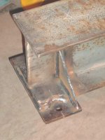
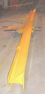
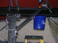
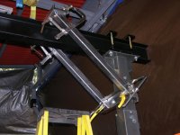
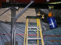
I needed a crane, but didn't wanna build one til I have a bigger area to work on tractors, dump truck, 50' manlift, etc, so I bought one of the HF "1 ton" cranes - the stock one is NOT wide enough to get my Case backhoe between the uprights, (the stabilizers don't clear) so I bought some 6" x3.33" I beam, 12.5#/foot (1" taller and .35" wider than the HF one) - cut a piece of that 12' long to replace the stock I beam.

I also did NOT like the way the stock beam mounts to the legs, plus I wanted the crane WIDTH adjustable and less likely to "fold up like a cheap suit", so I "borrowed" one of Royce's ideas for braces that do NOT get in the way of full travel of the trolley; then I made mine not only adjustable, but completely removable.

For now the crane needs to move around on gravel, so 8" casters from Surplus Center replaced the 5" stock ones - exact same bolt pattern, tough mod :=)

Here's what I did; the result is a much stronger joint, and the braces are just far enough apart to clear both a 1 ton chain hoist AND a 1 ton electric hoist - BOTH will be on the beam when I'm done fabbing the "minimum height loss" trolley mount for the electric hoist... Steve
 

Attachments

  • DSCN3102.jpg
    DSCN3102.jpg
    151.1 KB · Views: 114
  • DSCN3192.jpg
    DSCN3192.jpg
    145.8 KB · Views: 108
  • DSCN3205.jpg
    DSCN3205.jpg
    145 KB · Views: 108
  • DSCN3227.jpg
    DSCN3227.jpg
    151.8 KB · Views: 106
Last edited:

fiftyv8

Well-known member
Joined
Dec 29, 2018
Messages
237
Location
Perth
Boy, that is pretty neat BukitCase.
Does anybody body ever have the angled braces on the outer side so as to provide a touch more free travel between the upright posts?
 

BukitCase

Well-known member
Joined
Apr 11, 2017
Messages
1,075
Location
Oregon
Thanks Russ; strength-wise (and using the same design/materials) it shouldn't make any difference; but when you stop and think about it, with the exception of the top couple feet of post, the way I did it allows the maximum distance between posts for any given beam length. I can loosen a few bolts (5/8 grade 8, mostly) and move those clamps along the beam with a dead blow hammer - I need to relocate a bit more stuff before I can move it much tho...

Also, for my situation I needed a MINIMUM of 9 feet between posts in order to clear the stabilizers on my 580, and (other than smaller jobs) the main one I got this crane for was redoing the other 5 or 6 cylinders on the Case - the area that crane (and the hoe, soon) is in has about 14 feet usable width and 24' long with 11' headroom, just barely big enough for "me and my ho" :pimpflash

Later... Steve
 
Last edited:

Full Throttle

Well-known member
Joined
Nov 8, 2011
Messages
285
We use Aluminum Gantries from Spanco at work. Now we constantly tear down and haul from site to site.

The beam to upright connection has a ''boot'' (my term) flange atop with say 4x6 tube down as the leg slides in, with dogs that grip the beam, Allows gantry to be adjustable for width for use with multiple length I beams. Ours have no corner bracing from the upright to the beam. the uprights have holes drilled and locking pins that allow for height adjustments. they are very sturdy and I use them for 4'000# regularly.

f I were to build one It would be modeled after a Spanco, Aluminium if I had to tear it down on a regular basis, Steel if it was permanent and would definitely be height adjustable if I had to tear it down and move. Setting up a gantry 10ft-12ft in the air is no fun task.
 

sberry

Banned
Joined
Jun 18, 2005
Messages
35,747
Location
Brethren, Michigan
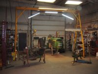
I changed the beam as I got one. It does come apart but I don't move it. It's been raised, it's been widened. 19 ft wide to fit the space and to unload truck or trailer sideways using trolly.
 

Attachments

  • A frame ladders (2).jpg
    A frame ladders (2).jpg
    146.3 KB · Views: 75
  • tractor lights.jpg
    tractor lights.jpg
    147.8 KB · Views: 68

matt_i

Well-known member
Joined
Mar 14, 2008
Messages
10,741
Location
SE Michigan
This is a structural steel "clip" which involves 1/2 of an I-beam, some round stock and some flat stock. Can be torch and ironworker-punching work. This would allow a person to place the columns anywhere on the I-beam and not affect its structural integrity as it would if the flanges were drilled.


Another design consideration for the casters revolves around trolleying the load to the extreme ends of the overhead rail. This puts all of the load (more or less) on 2 casters and so the casters should be rated for the intended load, or some type of "feet" could be employed to take the casters out of it. The horns on a swivel caster are the weak link and can fold up pretty easily.
 
To avoid these ads, REGISTER NOW!
Top Bottom