To avoid these ads, REGISTER NOW!

Ground verification test

Bigrhamr

Well-known member
Joined
Apr 16, 2009
Messages
293
Location
North Idaho
I'm setting up a piece of machinery and the manufacturer suggests verifying a good ground like this:

"Connect a 100 watt bulb between 120 VAC hot and the ground you are testing. Then measure voltage between 120 VAC neutral and the ground, voltage should be below 0.75 volts"

I did that and get just over 25 volts, repeated the test right at the ground rod with the same results. So I'm going to get a new copper ground rod to replace the old one which looks like it is very rusty bare steel, plus the dirt is bone dry and I don't know how long the old rod is.

Can someone please explain in easy to follow terms what the bulb is doing in this test? And secondly does it sound like the best or right way to test the ground? :headscrat
 
To avoid these ads, REGISTER NOW!

tcianci

Well-known member
Joined
Feb 7, 2009
Messages
4,242
Location
Walpole, Ma
Sounds like you do indeed have a bad ground but changing the rod won't fix it. The test they describe measures for a voltage drop from neutral to ground... the neutral and ground are common at the main panel only not at any sub panel in the system. If you are reading a voltage drop of 25 volts, you need to check the general neutral and ground wiring from where you are testing back to the panel. Your ground rod was copper plated at one time when it was new. If you could cause a current to flow through the ground rod (which this test cannot do) and have a way of measuring the voltage at the earth, you could determine the functionality of the actual ground rod, but that is not what is in question here. Leave the ground rod alone and look for a bad connection in your grounds and neutral between where you are installing your stuff and the main panel.
 
OP
B

Bigrhamr

Well-known member
Joined
Apr 16, 2009
Messages
293
Location
North Idaho
Sounds like you do indeed have a bad ground but changing the rod won't fix it. The test they describe measures for a voltage drop from neutral to ground... the neutral and ground are common at the main panel only not at any sub panel in the system. If you are reading a voltage drop of 25 volts, you need to check the general neutral and ground wiring from where you are testing back to the panel. Your ground rod was copper plated at one time when it was new. If you could cause a current to flow through the ground rod (which this test cannot do) and have a way of measuring the voltage at the earth, you could determine the functionality of the actual ground rod, but that is not what is in question here. Leave the ground rod alone and look for a bad connection in your grounds and neutral between where you are installing your stuff and the main panel.

It's a good thing you mentioned that and made me take a closer look. This is coming off of a sub panel but the ground and neutral do appear to be common since what I believe is supposed to be a floating neutral bar has a bonding strap going to the metal enclosure. Is this sub panel even supposed to have it's own earth ground or should it just ground back through the main panel? Thanks for the help.
 

tcianci

Well-known member
Joined
Feb 7, 2009
Messages
4,242
Location
Walpole, Ma
From what I understand, and I checked this with my electrician, the neutral and the ground should be common only at the main panel. If you have any sub panels the neutral and grounds should be separate, Maybe what you're seeing is just a ground connection for the enclosure itself.
 

ArthurPE

Banned
Joined
Jun 14, 2009
Messages
423
From what I understand, and I checked this with my electrician, the neutral and the ground should be common only at the main panel. If you have any sub panels the neutral and grounds should be separate, Maybe what you're seeing is just a ground connection for the enclosure itself.

or the R of some connected load...

without getting too crazy with the math
you can set up simultaneous equations for the V drop across the light, and the V drop G-N...
V=120
Vlight = 120 - VGN (measured)

the short of it when you do so you get:
(120-VGN)/VGN = Rlight/RGN
Rlight is a variable inductive load...it's R depends on I...not constant

say you get VGN=1VAC
119/1=Rlight/RGN

it can be calculated (and/or measured) that Rlight (100W) at 119 VAC is ~142 ohm, at 120 ~ 144 (don't ask how :))

so RGN = Rlight/119 = 142/119 ~ 1.2 ohm

if VGN = 0.75 as recommended
119.25/0.75 ~ 159
RGN = Rlight/159 = 142.5/159 ~ 0.9 ohm < 1 ohm, which is what they are looking for...

I used some approximations, and assumed a V of 120, etc.

but that's the theory
 

walrus

Well-known member
Joined
Nov 12, 2008
Messages
11,685
Location
Maine
It's a good thing you mentioned that and made me take a closer look. This is coming off of a sub panel but the ground and neutral do appear to be common since what I believe is supposed to be a floating neutral bar has a bonding strap going to the metal enclosure. Is this sub panel even supposed to have it's own earth ground or should it just ground back through the main panel? Thanks for the help.

2008 code, if its a detached building from where the main is, it should have 2 ground rods but should also have a 4th wire coming from main attached to ground bar in panel, bolted to can, neutral bar should be isolated from can.
 
OP
B

Bigrhamr

Well-known member
Joined
Apr 16, 2009
Messages
293
Location
North Idaho
2008 code, if its a detached building from where the main is, it should have 2 ground rods but should also have a 4th wire coming from main attached to ground bar in panel, bolted to can, neutral bar should be isolated from can.

Okay here's what I've got. It is a detached building, the whole setup is probably a bootleg job, not permitted or to code so I am not assuming anything is right or done for a reason.

There are three wires into the can, 2 hots and the neutral which goes to a buss that is insulated from the can (Is floating the right term?)

The ground buss is attached to the can via a copper strap and uses a copper wire going to the earth ground rod. There is no 4th wire going back to the main panel. I can see that's not to modern code but if it has a good ground rod is that going to be safe? Won't an earth ground perform the same function at the sub or back at the main 100 feet away?

Now what the problem seems to be is they have neutrals and grounds connected to the same busses so the neutral is not a loop back to the main but effectively goes to ground at the sub panel ground.

So I'm going out now to seperate the grounds and neutrals then re test. Might be ripping the whole sub out and replacing it but I want to at least identify the problems.
 

Aceman

Well-known member
Joined
Jan 28, 2007
Messages
2,513
Location
Eastern Oregon
There are three wires into the can, 2 hots and the neutral which goes to a buss that is insulated from the can (Is floating the right term?)

So I'm going out now to seperate the grounds and neutrals then re test. Might be ripping the whole sub out and replacing it but I want to at least identify the problems.

STOP! You're going to kill someone.

Since this is not a 4-wire feed, it has different rules!

Are there any other metallic paths between this garage and your home? Water lines, telephone, gas, coax, clothesline, whatever?

If there isn't another metallic path, bond the neutral along with the grounds to your panel in the garage. Do not float anything!

If there is another metallic path or you're under the 08 code you must pull that 4-wire, the ground wire. Shut the power off to your garage panel until you do so!

To summarize:

3-wires fed to a building with no other metallic paths, bond the neutral to the can. New 08 code now requires 4-wires, period.

4-wires fed to a building regardless of whether or not there are other metallic paths, float the neutral.
 
Last edited:

walrus

Well-known member
Joined
Nov 12, 2008
Messages
11,685
Location
Maine
There are three wires into the can, 2 hots and the neutral which goes to a buss that is insulated from the can (Is floating the right term?)

The ground buss is attached to the can via a copper strap and uses a copper wire going to the earth ground rod. There is no 4th wire going back to the main panel. I can see that's not to modern code but if it has a good ground rod is that going to be safe? Won't an earth ground perform the same function at the sub or back at the main 100 feet away?

Now what the problem seems to be is they have neutrals and grounds connected to the same busses so the neutral is not a loop back to the main but effectively goes to ground at the sub panel ground.

So I'm going out now to seperate the grounds and neutrals then re test. Might be ripping the whole sub out and replacing it but I want to at least identify the problems.

Do not seperate anything. A 3 wire sub panel to a detached building was fine and dandy one code ago, if and only if there were no metallic paths back to the building that housed the main. This is very important if you ever lose the neutral. If your going to replace, then 4 wires, 2 ground rods.
 

tcianci

Well-known member
Joined
Feb 7, 2009
Messages
4,242
Location
Walpole, Ma
I can see the reasoning behind the proper grounding, but I can't see where any of that is going to fix the large voltage drop he has measured, please explain.
 
To avoid these ads, REGISTER NOW!

ArthurPE

Banned
Joined
Jun 14, 2009
Messages
423
you're OK, as is...
you in essence have 2 ground fault paths
one thru the local rod, and one via the N/gnd bonding jumper/rod(s) at main panel

if you lost the N the local gnd still affords protection, ie, the faulted equipment won't be at line potential, it will be grounded
 
OP
B

Bigrhamr

Well-known member
Joined
Apr 16, 2009
Messages
293
Location
North Idaho
STOP! You're going to kill someone.

Since this is not a 4-wire feed, it has different rules!

Are there any other metallic paths between this garage and your home? Water lines, telephone, gas, coax, clothesline, whatever?

Okay, you convinced me to not touch anything until I understand it fully.

There are no other paths between buildings.

So, just to be crystal clear if I only have the three wire then the grounds from all circuits in the garage, all neutrals in the garage, and the subpanel cabinet in the garage should be bonded together and return to ground at the main panel via the 3rd wire?

The part I can't seem to wrap my brain around is what is the difference between grounding back to the main via the 4th wire and going to an earth ground from the sub panel? Not trying to be argumentative here, I just don't get it.
 

ArthurPE

Banned
Joined
Jun 14, 2009
Messages
423
I can see the reasoning behind the proper grounding, but I can't see where any of that is going to fix the large voltage drop he has measured, please explain.


good point

OP, is there any neutrals on the isolated bar?
his bonding at the main sounds shaky
 

ArthurPE

Banned
Joined
Jun 14, 2009
Messages
423
The isolated bar has neutrals on it and one ground wire on it. The bar that is bonded to the cabinet has grounds only.

so all N go to the isolated (non grounded) bar, except one gnd
and the rest of the grounds go to the gnd bar which is tied to the gnd rod...

the one gnd on the N bar, is it a conductor from a branch circuit or is it a jumper to the gnd bar?
 
OP
B

Bigrhamr

Well-known member
Joined
Apr 16, 2009
Messages
293
Location
North Idaho
so all N go to the isolated (non grounded) bar, except one gnd
and the rest of the grounds go to the gnd bar which is tied to the gnd rod...

the one gnd on the N bar, is it a conductor from a branch circuit or is it a jumper to the gnd bar?

The one ground on the N bar is from a branch circuit.
 

ArthurPE

Banned
Joined
Jun 14, 2009
Messages
423
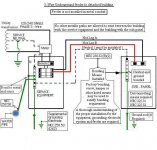
you need to bond the N and G in the sub-panel
in essence you have a service entrance with derived ground
this is per NEC 2005, if 2008 you must have gnd from the service panel
 

Attachments

  • 3%20wire%20feeder%20to%20detached.JPG
    3%20wire%20feeder%20to%20detached.JPG
    76.4 KB · Views: 32
  • 4-%20wire%20subpanel%20detached.jpg
    4-%20wire%20subpanel%20detached.jpg
    87.5 KB · Views: 31
Last edited:
OP
B

Bigrhamr

Well-known member
Joined
Apr 16, 2009
Messages
293
Location
North Idaho
you need to bond the N and G in the sub-panel
in essence you have a service entrance with derived ground
this is per NEC 2005, if 2008 you must have gnd from the service panel

Okay, did that and repeated the test, results now 0 volts.
Thanks for all the input!
 

ArthurPE

Banned
Joined
Jun 14, 2009
Messages
423
no prob...

how did you bond it?
the lug that came with the panel or a jumper wire?
 

ArthurPE

Banned
Joined
Jun 14, 2009
Messages
423
Jumper wire.

what size breaker feeds the sub-panel?
what size wire?

I would use a solid piece of copper, I would guess #6 minimum...
the N should be bonded to the enclosure and the ground lugs...

I don't have a code book here, but tell me the CB and wire size and I'll post it tomorrow...
 

ArthurPE

Banned
Joined
Jun 14, 2009
Messages
423
I used #4 copper for the jumper. The breaker is 80 amps and the wire is 1/0 Aluminum.


good, that's plenty either based on conductor or breaker...

just make sure it's bonded to the lugs and enclosure

one piece of copper
from an N terminal, then run thru a G termianl and on to a clamp or factor ground point to the enclosure...prepped and stripped appropriately
 
To avoid these ads, REGISTER NOW!
Top Bottom