To avoid these ads, REGISTER NOW!

Gte718p ' s CNC project

gte718p

Well-known member
Joined
Mar 12, 2009
Messages
3,972
Gte718p ' s CNC Mill Build

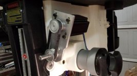
My new toy showed up today. I got an awesome deal from Enco on cyber Monday so I picked up a standard Chinese mill drill. It came well packaged and had extras in the box including an angle vice and a clamp set that I was not expecting. Even better it was not packed with chineses grease. Just a surface coat that cleaned up fairly easily.

attachment.php


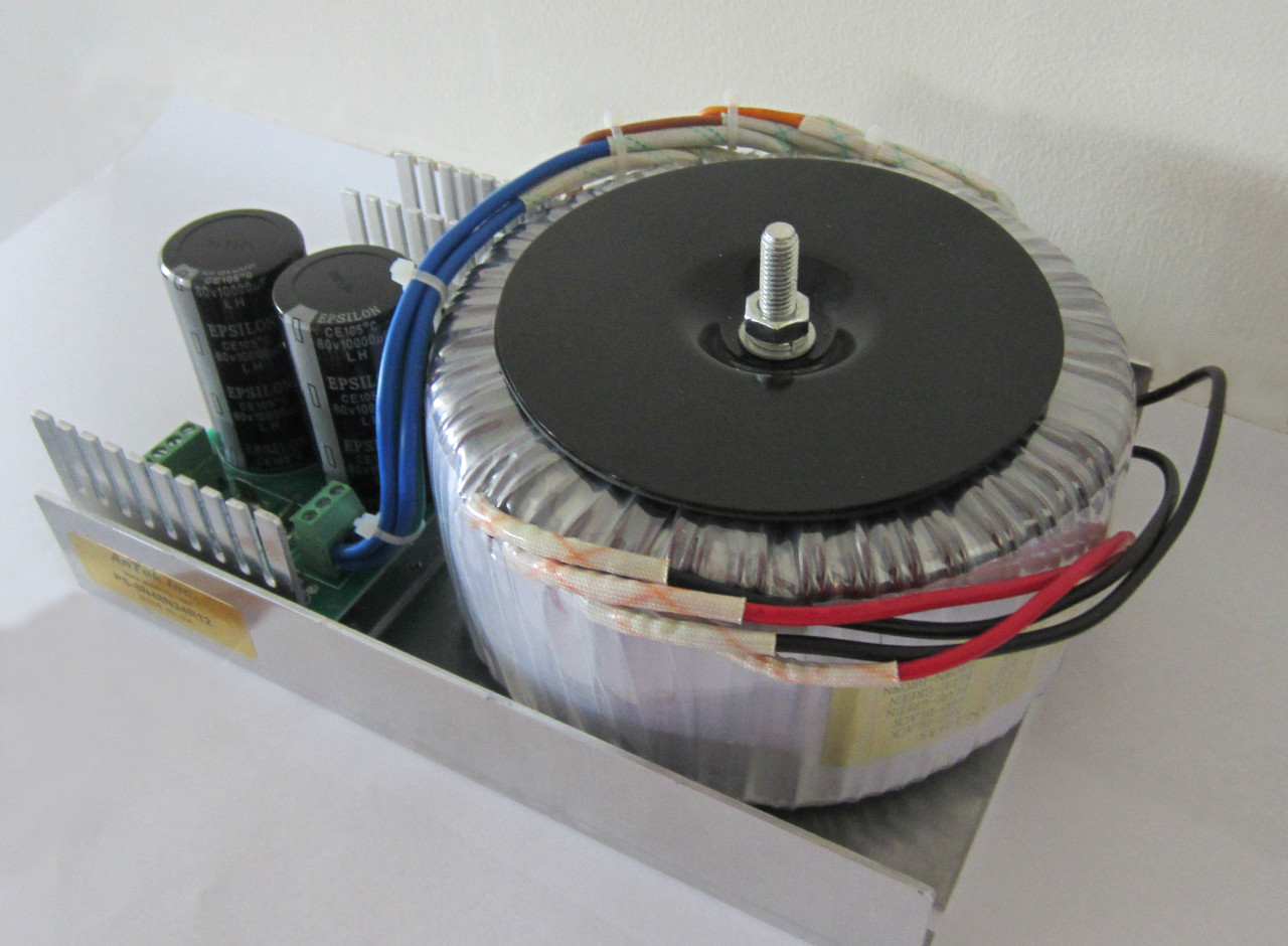
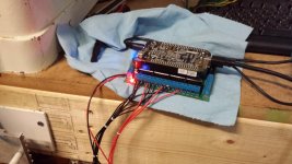
This will eventually become a cnc machine. I've done most of the controls already. This is my dirt cheap controller project. It was origionally designed for the smaller HF mill. I'm hoping it will be powerful enough for this mill. If not I'm already planning on using the controller for multiple projects, I'll have to build a more robust control for the mill. I have about $200 in the control system.

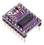
It is based on the Arduino micro controller running GRBL an open souce Gcode interpreter.
attachment.php


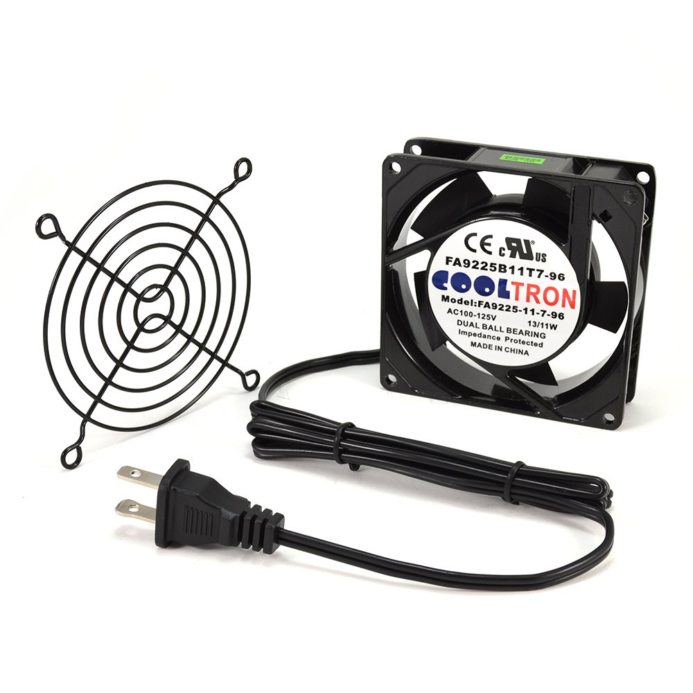
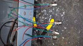
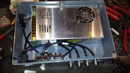
The connectors are all panel connectors for avaition headphones. They are cheap and work welll.
attachment.php


All wired up
attachment.php


attachment.php


attachment.php


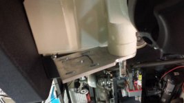
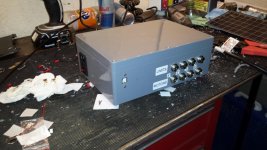
Temporarily finalized and closed up
attachment.php


I'm going to go back and add limit switches and a pendant for controlls later, but it is operational now.
 

Attachments

  • 20141209_171459.jpg
    20141209_171459.jpg
    140.3 KB · Views: 1,135
  • 20141202_185151.jpg
    20141202_185151.jpg
    150.8 KB · Views: 1,117
  • 20141202_184531.jpg
    20141202_184531.jpg
    151.8 KB · Views: 1,097
  • 20141202_184517.jpg
    20141202_184517.jpg
    148.8 KB · Views: 1,101
  • 20141202_152007.jpg
    20141202_152007.jpg
    156.5 KB · Views: 1,103
  • 20141202_162649.jpg
    20141202_162649.jpg
    157.8 KB · Views: 138
  • 20141202_172548.jpg
    20141202_172548.jpg
    154.3 KB · Views: 1,121
Last edited:
To avoid these ads, REGISTER NOW!

404

Well-known member
Joined
Aug 23, 2014
Messages
3,463
Location
Mass
Tell me how cool air gets into the box and hot air gets out....
 
OP
G

gte718p

Well-known member
Joined
Mar 12, 2009
Messages
3,972
Tell me how cool air gets into the box and hot air gets out....

Not shown in the pictures, but I used the mill to to put about a dozen slits in the backs side opposite the plugs. I also put a 3.5" hole in the top and stuck a 4" 120v case fan on the top. I have a fairly fine mesh installed on both to keep chips out. The fan moves a ton of air. I also have large aftermarket finned heat sinks on all of the chips. I'm hoping it will be enough to keep the driver chips cool as they are going to be running right at the ragged edge of their spec.

Running unloaded I was able to run for almost an with the sealed box before heat became an issue. Obviously once I get the motor mounts done, and am loading the steppers it is going to generate a ton more heat. I'm not sure I have enough cooling, but I'm hoping. The driver chips have built in thermal control and they are cheap if I melt them. If I do, I'll have to rethink the design.

61KdkfH0PfL._SL1000_.jpg


This project along with my jack rebuild has stalled due to taking a rather unplanned nine month "vacation." I'm looking forward to continuing this project when I get home.
 
Last edited:

Macrosloth

Well-known member
Joined
Apr 27, 2012
Messages
86
Location
Van
What weight stepper motors, and how many amps can that Arduino output?

Did you ever look at GRBLSHIELD?
 
OP
G

gte718p

Well-known member
Joined
Mar 12, 2009
Messages
3,972
I'm using 425 oz steppers. I'm not sure they will be strong enough. The arduino can drive the steppers directly. It is limited to .2 amps and 5v. The motor controller chips I'm using are good for 42 volts and 4 amps.

I'm using the CNC shield.
http://blog.protoneer.co.nz/arduino-cnc-shield/

I did look at GRBLSHIELD I like the motor controller chips to be replaceable.
 
OP
G

gte718p

Well-known member
Joined
Mar 12, 2009
Messages
3,972
A little progress was made today. Not on the CNC portion but on the mill. I have two axis of the DRO working. I do intent to use the encoders as feedback in a fork of GRBL that I am working on. It is however a very low priority.

20151021_154027.jpg


20151021_153926.jpg


20151021_153916.jpg


20151021_153939.jpg


20151021_153952.jpg


20151021_153853.jpg


20151021_153846.jpg


It went fairly well. For the X axis, I milled two aluminum pieces to fit in the dovetail and two aluminum shims to space the encoder out. I had to modify the bracket for the X axis. The Y access I used two screw hole conveniently already on the machine for the encoder track. There are also two bolt holes on the back of the table. I built a little sheetmetal bracket to connect the two. I'll probably go back an mill something fancier later, but it works. Still have the Z axis to do, but I'm not in a hurry to mess with it yet.

Next project is the get a better display. I have all the parts to build Yuriy bluetooth display for the imaging scales.

http://www.yuriystoys.com/2014/11/touchdro-version-2-now-available.html
 
OP
G

gte718p

Well-known member
Joined
Mar 12, 2009
Messages
3,972
DRO is done

Parts:
3x Igage DRO scales - $100 (Ebay)
Kindle Fire 7in - $50 (Amazon)
Ardunio UNO - $7 (Amazon)
Arduino Protoshield - $4 (Amazon)
HC-06 Bluetooth - $8 (Amazon)
Project box - $4.5 (Radio Shack)

Step One: Fix the Kindle Fire.

The Kindle comes with Amazons custom version of the Android Operating system. It also displays adds on the lock screen which is annoying. Unfortunately Amazon does not include the googleplay apps store or a decent browser. You need googleplay to download Yuri's DROTouch software.

I used instructions from RootJunkie to load Google Appstore. The files you need can be found on here. If you use a PC there is a single click option. Unfortunately I'm a Mac guy so I had to do it manually. It is not hard thought.
1. Download drivers.
2. Place Fire in developer mode by tapping serial number (under device options) multiple time.
3. Under developer tab enable ADB
4. Download files from RootJunky
5. In terminal change directory to the directory you saved the files to
6. Place Fire in
7. at the command line enter:
adb start-server
adb install com.google.android.gms-6.6.03_(1681564-036)-6603036-minAPI9.apk
adb install GoogleLoginService.apk
adb shell pm grant com.google.android.gms android.permission.INTERACT_ACROSS_USERS
adb shell pm hide com.amazon.kindle.kso
adb kill-server
-I hade to remove the parentheses from the first file name to get it to work on a MAC.
8. Download DROtouch from Google Play Appstore.

2. Step Two: Build the circuit.
Yuris instructions are pretty good. The only thing I think needs to change is the HC-06 is not 5v tolerant. As a result you need another voltage divider for the output.

Another thing that caused me problems it you wire the transmit pin (TX) on the arduino to the RX on the bluetooth module.

I chose to cut the USB connecter of the gauges. There are five wires in the USB wire. Red, Black, Green,Blue, Yellow.
Red - +3V
Black - Ground
Yellow - Signal

On two of my scales the clock wire was blue. On the third one clock was green. That took a long time to figure out.

20151112_173856.jpg


20151112_173909.jpg


20151113_203641.jpg


20151114_115050.jpg


20151114_161719.jpg
 
Last edited:
OP
G

gte718p

Well-known member
Joined
Mar 12, 2009
Messages
3,972
X axis is done

20151228_153307.jpg


Works well. I have a little problem with back lash right now. The hand wheels are what locates the lead screw. There is a brass spacer between the gear and the housing that is about .03" short and it is creating a little bit of a problem. Not an issue when using the DRO, but it will become an issue once I have the full CNC setup up and running. It will be an easy fix, but I don't feel like yanking it all apart to fix right this moment.

I still have to make a replacement handle.

The electronics are working well with one exception, the table always moves in one direction. Oops. I've got it ripped apart to figure that out right now. I was worried I would not have enough power to move the table. It works great. It has accelerates smoothly, travels with good speed and moves the table without breaking a sweat.

I'm using bCNC to parse Gcode to the GRBL. I'm running it on a Raspberry Pi and it is running well. Pretty cool little program. Lots of features and you can't beat the price of free.

In addition to getting the CNC part up, I have to software projects running. I want to incorporate the DRO for a feedback loop to the control program. I also am working on a program to allow me control the mill from a PS4 game pad. I had to write my own driver for the Raspberry to connect with the PS4 so that has been a fun learning experience.

Next up. Y axis
 
Last edited:
OP
G

gte718p

Well-known member
Joined
Mar 12, 2009
Messages
3,972
Not a lot of traffic through here.

I spent a few hours racking my brain on why the table would only move in one direction. I checked connections, wiring, and signal paths about a dozen times. Turns out all three of my brand new genuine Pololu control chips are defective. All in the same way. What are the odds? I have some knock off Chinese ones from or another project. Threw them in and it works perfectly.

0J5806.150.jpg


The Chinese versions get hot fast. I doubt they have the current limiting and thermal protection of the authentic chips. I'll see if they last, if not I'll have to upgrade to real stepper drivers. Probably break down and get some Geckos.
 

Maexle

Well-known member
Joined
Apr 9, 2012
Messages
900
Location
https://t.me/pump_upp
Very interesting thread, I like your work. I have build myself a CNC router last year, works like a charm.

link:


And yes, I plan on upgrading or even build a bigger one in the future with Geckos and linear ball screw drives.
 
Last edited:
OP
G

gte718p

Well-known member
Joined
Mar 12, 2009
Messages
3,972
Maexie

Very nice.


In other news, the New Years vacation allowed me to finish up the Y axis:

20151231_203133.jpg


20151231_203313.jpg


And the entire setup:

20151231_203206.jpg


The main mechanical parts are complete. After the pictures I went back and added a hand wheel to the Y axis. I took the original handle, drilled holes through it and the gear, tapped the gear and put 3 M4-.7 machine screws in it. Seems to work great. I'm finding a good bit of irony in the fact I'm using a 1946 drill press and a 1946 lathe to build a modern CNC mill.

Sadly the electronics let me down. I'm not really surprised, but the control is undersized. I was wrong about the Chinese knock off chips. They do have thermal protection. However it kicks in way to soon. The chips are not even getting hot and they are scaling back current. After about 5 or 6 moves the control side shuts down. Oh well off to by some Geckos.
 
OP
G

gte718p

Well-known member
Joined
Mar 12, 2009
Messages
3,972
ITS ALIVE!!!!

Ordered the Geckos. I went with the G213V digital steppers. I ended up getting them for ~$110 each on eBay.
The current electronics setup is a 36 volt 12 amp power supply, Raspberry PI, Arduino Uno running GRBL, and 3 G213V digital stepper controllers.

The x axis was not as steady as the Y axis. It likes to bounce. I added a brace to the X axis mount. That mostly sorted out the bounce.

I also completely disassembled the table to clean an lubricate it. It move much better now. In reinstalling the table I adjusted the backlash on the lead screw and am now less then .008"

I haven't cut anything yet, but have run the first couple of programs. It runs awesome. I can't wait to start making chips. Before I do that I have to sort out how I'm going to mount all the electronics.

Pictures tomorrow.
 
Last edited:

WhoWhatNow

Well-known member
Joined
Feb 22, 2011
Messages
1,885
Location
Collegeville, PA
Watching this thread. I picked up an Amazon Fire and a Arduino for Dummies book after seeing your DRO build thread. Going to make that one of my winter projects.
 
OP
G

gte718p

Well-known member
Joined
Mar 12, 2009
Messages
3,972
Watching this thread. I picked up an Amazon Fire and a Arduino for Dummies book after seeing your DRO build thread. Going to make that one of my winter projects.

Watch out Arduinos are addictive. I have 7 or 8 or them floating around the house in various projects.
 

LXCam

ALLIANCE MEMBER
Joined
Apr 23, 2013
Messages
19,109
Location
AZ
WOW!, that's a ton of effort you're putting into that mill. But still it's very cool. Just a little warning maybe. It appears you and I have the same scales, but I use mine on my 14/42 lathe. I found out something interesting about these that may or may not impact your project so take this for what it's worth. If memory serves me correctly I recall those having a tolerance of +/- .0015-.002 per 6". For me that was fine until I figured out the hard way that tolerance could occur anywhere within the length of the scale and is not linear by any means. So for myself, when I need repeat-ability it's either triple check as it goes or use dial indicators which is much better anyhow.

So good luck, I can't wait to see this in action!.
 
OP
G

gte718p

Well-known member
Joined
Mar 12, 2009
Messages
3,972
Reenforced X axis:

20160110_182923.jpg


20160110_182933.jpg


Once I got everything working I tore it all apart to do the final mounting of the stepper controllers. I used the CNC to cut a ghetto heat sink pattern in an aluminum plate. The steppers are held on by two brass retaining rails. The Geckos require a heat sink when operated above 3 amps. I'm running right at three amps right now so I don't actually need it, but I figure it can't hurt.

20160113_170856.jpg


20160113_170902.jpg


20160113_170918.jpg


Started the wiring for the final time:
20160113_191556.jpg


Potentially a video:
20160112_175606.jpg
 
Last edited:
To avoid these ads, REGISTER NOW!
OP
G

gte718p

Well-known member
Joined
Mar 12, 2009
Messages
3,972
I know, they kind of multiply like rabbits. I have several Unos lying around the house.

Your not kidding, I just ordered another nano today to drive an LED project for this weekend.

WOW!, that's a ton of effort you're putting into that mill. But still it's very cool. Just a little warning maybe. It appears you and I have the same scales, but I use mine on my 14/42 lathe. I found out something interesting about these that may or may not impact your project so take this for what it's worth. If memory serves me correctly I recall those having a tolerance of +/- .0015-.002 per 6". For me that was fine until I figured out the hard way that tolerance could occur anywhere within the length of the scale and is not linear by any means. So for myself, when I need repeat-ability it's either triple check as it goes or use dial indicators which is much better anyhow.

So good luck, I can't wait to see this in action!.


I'll keep an eye on that. I'm having trouble getting it dialed in for the correct number of counts per inch. I'm getting close but over a long range it is not accurate yet. Over 30 inches of travel it adds up. So far repeatability has been good.
 
OP
G

gte718p

Well-known member
Joined
Mar 12, 2009
Messages
3,972
Tore everything down for the last time to paint the base plate and to begin final assembly.

Mounting plate with a nice coat of white paint:
20160118_130858.jpg


Installed the stand off
20160118_141554.jpg


Installed the control section for the last time:
20160118_142149.jpg


Made a lexan shield to protect the electronics from chips. I'm going to have to make another attempt at this. I got the lexan to hot while bending it and there are bubbles all along the bend line. It is not pretty, but it will be functional.
20160118_150821.jpg


Final wiring:
20160118_154945.jpg


Finally mounted to the bench under the mill:
20160118_155620.jpg


20160118_155630.jpg


I also like physical buttons so I wired up the pendant. It plugs into the last connector on the right.

20160118_132949.jpg


Everything work. I'm still having some electrical problems. Jogging is not working. I haven't had this problem on any of the tests so far. When I jog, the steppers whine and then start spinning at the very end of the move. Normal G1 moves work fine. I also still have to dial in the steps per mm. Right now a one inch move is only about .875" It is just a setting issue.

I'm going to get the settings dialed in and then start on the z axis.
 
OP
G

gte718p

Well-known member
Joined
Mar 12, 2009
Messages
3,972
This thing is kicking my @$$.

Everything works, and I've run a good bit of code, but the scale is off.

The lead screw is .1 in a revolution
there is a 2/5 gear reduction
steppers are 200 steps a rotations
1 in = 24.5mm
Steppers are set up for 5 micro steps.

by my math that means I should have 984.25197 steps a mm. By guessing at numbers I can get pretty close, but not exact.

unfortunately I'm getting .26 in of movement for a .5in command. I'm also getting killed by backlash. Unfortunately GRBL doesn't have backlash compensation which might kill this iteration of the project. Manually accounting for backlash it is very repeatable, but it walks off a consistent amount with each direction change. The backlash on these lead screws is huge.
 
OP
G

gte718p

Well-known member
Joined
Mar 12, 2009
Messages
3,972
Not a lot of progress to report.

This is a continuous upgrade. I found a good deal on a better power supply. I'm upgrading from a generic 36 volt Chinese power supply to a US build 77V power supply.

IMG_1369n__17019.1390598557.1280.1280.jpg


I've started using Inkscape to generate images and Gcode. Inkscape is another freeware/GNU product that does vector images. It has a plug in that will generate Gcode directly from the vector image. It is a little cookie to get started with, and not exactly user friendly. However, there are good YouTube walk throughs. Once you have been through it a couple of times and have the order of operations down it works extremely well.

The machine is up and cutting. I still have not go the backlash and step size correct. However, I am doing engravings on wood and plastic where the size is not critical. It does nice work on simple objects.

I'm having a problem on more complex shapes. I have not built the Z axis yet. To do traverses, I have to stop manually move the z axis, let the machine move to the starting point of the next path, lower the z axis, and let the coe run. The hold cycle is acting funny. The machine holds as soon as the hold is sent, even if there are commands in the queue. On cycle start it seems to skip the first couple of steps. I'm not sure if the problem is in the Gcode, GRBL, or the parsing program I am using. I have a few things to test and I hope to have that fixed this week.
 
OP
G

gte718p

Well-known member
Joined
Mar 12, 2009
Messages
3,972
Power supply showed up from Antek today. That is a serious piece of equipment. It is every bit of 20lbs of copper. It came extremely well packed with styrofoam and three over boxes. There was zero chance this thing was going to move and damage it's self in transit. I haven't had a chance to hook it up and outset it yet, but so far I'm very impressed.
 
OP
G

gte718p

Well-known member
Joined
Mar 12, 2009
Messages
3,972
I'm up and running on the new power supply.

I'm still having problems with pauses in the Gcode. I ran the same code twice. Once I left the Z movements in the code and allowed the tool to drag during the rapids. The second time I took all the Z movements out and substituted M0 to pause the code and allow me to move the Z axis manually.
 
Last edited:
OP
G

gte718p

Well-known member
Joined
Mar 12, 2009
Messages
3,972
I finally figured out the problem with the M0 code. The GRBL has a disable feature to turn off the stepper drivers a few microseconds after it finishes the last command. Turns out the drivers where not reenabling fast enough and I was loosing a bunch of steps. I've disabled the disable feature and I'm off and running.

Also finished the Z axis, but the pictures don't want to play.
 

Attachments

  • 20160210_200446.jpg
    20160210_200446.jpg
    138.2 KB · Views: 45
  • 20160210_200453.jpg
    20160210_200453.jpg
    140.9 KB · Views: 41
  • 20160210_210658.jpg
    20160210_210658.jpg
    140.3 KB · Views: 47
Last edited:
OP
G

gte718p

Well-known member
Joined
Mar 12, 2009
Messages
3,972
Back from the dead. I've enjoyed having the mill for the last few months. I'm mainly using it as an oversized engraver. I have done some extremely cool emblematic stuff for the house and made several tools and parts that have saved me significant amounts of time and money.

Unfortunately I've run into the limits of the control scheme. It is time for the project to evolve one more time. Besides building it is half the fun. GRBL and the ardiuno have been very good, especially for the price. ($10) However, GRBL in its current iteration has one major draw back. The motion planner does not take backlash into account. This being a Chinese mill that has not yet been converted to ball screw, it has a good bit of backlash. This significantly limits my ability to do detailed work.

The solution was to upgrade the controls to LinuxCNC. There are a couple of ways to go about it, the simplest and most common is to find an old PC with a parallel port. I don't have an old PC, didn't want to source one, and generally didn't like idea. I'm going with a single board computer, BeagleBone Black running a fork of Linuxcnc called Machinekit and a Probotix PBX-BB interface board. The setup is a little more expensive at around $150 total significantly more powerful.

500px-PBX-BB.jpg


Machinekit is a nice bit of software. It is freeware so the price is definitely right. However, it is not exactly user friendly. I would recommend being at least conversant in Linux before attempting to set it up. I consider myself extremely computer savvy and it took a week to work through all the setup issues. Setting up the mill also involves building a .HAL file which is basically a program written in a scripting language that connects inputs to variables in the program.
http://www.machinekit.io/

Why if was worth the effort:
-backlash compensation
-ability to tune to the stepper drivers allowing higher stepping rates without missing steps
-much better trajectory planner
-smooth jogging
 
Last edited:
OP
G

gte718p

Well-known member
Joined
Mar 12, 2009
Messages
3,972
The actual setup before it was mounted safely under the bench.

attachment.php
 

Attachments

  • 20160607_153721.jpg
    20160607_153721.jpg
    144.5 KB · Views: 263
OP
G

gte718p

Well-known member
Joined
Mar 12, 2009
Messages
3,972
Posting for info.

I am extremely happy with the final result. The BBB running MachineKit has been awesome. After some careful measuring, I was able to basically eliminate backlash with the backlash compensation settings. I can now hold .001" repeatable over the entire travel of the machine and much better in the main working area. the screw is not uniform so I biased the machine to where I normally work. It is repeatable to +-3 tenths in the main work area.

The magic number for my machine was .031468 on X and .03821 on Y. That is entirely dependent on the machine and will change as the screw wears or if you change the traveler block.

The other thing I like is Machinekit does a much better job with jogging. It is very smooth in the semi automatic mill mode.

Next step will be a new pendant. I'm either going to buy one of these http://vistacnc.com/ or build one very similar.

Unfortunately I've moved (joys of working for the government) and the mill didn't come with me. Hopefully my father-in-law will enjoy it for the next couple of years.
 
Last edited:

braidmeister

Well-known member
Joined
Mar 31, 2011
Messages
589
Good for you man. It's an adventure with this stuff. Always learning and improving.

Be sure to keep a journal of sorts for yourself (and backups) so that down the road if lightning strikes or something dies, you can get back to square one without needing to do a bunch of research again.
 
OP
G

gte718p

Well-known member
Joined
Mar 12, 2009
Messages
3,972
Good for you man. It's an adventure with this stuff. Always learning and improving.

Be sure to keep a journal of sorts for yourself (and backups) so that down the road if lightning strikes or something dies, you can get back to square one without needing to do a bunch of research again.

Funny you should mention it. When I moved the mill south, the memory card rattled out of the holder. It looked seated but wasn't. Unfortunately it corrupted the card when I booted up the machine. Originally I couldn't find my backup image so I attempted to create everything from scratch. Boy was that a pain. I did find the backup, but my backup image was not up to date, and it took a long time to get all the settings current again.

That is part of the reason I made the thread here and on CNC zone. It is an enduring memory of all the steps and little lessons learned.
 

braidmeister

Well-known member
Joined
Mar 31, 2011
Messages
589
Been there...a number of times. I made a living for a long time with CNCs. I've got spares of everything in case I am in the middle of a job and something takes a ****.

Rock on & keep a cool tool :D
 

big_bake

Well-known member
Joined
Mar 19, 2014
Messages
119
Location
VA
very cool project. also saw an older post that had the inch to millimeters conversion wrong. I'm sure you sorted it out though.
 
OP
G

gte718p

Well-known member
Joined
Mar 12, 2009
Messages
3,972
The goal of this project was learn and gain some experience for a future build. As a result, the goal was always to do this on the cheap. I think I succeeded. Ignoring the miss steps along the way the final cost was about $700. While not a HAAS or even a Bridgeport, it hold very good tolerances and makes really nice parts. Some of the things I have done include making my own PCBs, engraving emblematic, and custom brackets for the truck.

Final:
3x380 oz stepper motors - $100
3xGecko motor controllers -$333
Beagle Bone Black -$55
PBX-BB shield -$90
Gears and belts -$40
Aluminum -$30
Misc connectors/wires ~-$25
-----------------------------------------
$683
 

stioc

Well-known member
Joined
May 2, 2005
Messages
1,317
Location
SoCal
Hey, bringing this back up for a few questions. I had this thread bookmarked from when you posted in my RF31 mill purchase thread. So after recently building a small GRBL based 3-axis CNC router I have a much better understanding of CNC -though CAD/Fusion360 is still kicking my behind but that's another story :p

1. Based on your experience with the GRBL looks like I should go with LinuxCNC or Mach 4 perhaps? It's 2018, I don't want no stink'n parallel ports lol Do you have an opinion on the selection here? I hear ToolPath (Tormach) is based on LinuxCNC which makes me interested in LinuxCNC though I haven't researched it at all. I suspect, the supported motion controller may be different for LinuxCNC vs. Mach 4. I was leaning towards this with Mach 4: http://www.pmdx.com/PMDX-424 http://www.pmdx.com/SmartBOB-compare - Linux itself is not a problem, I've been a *nix guy for 20+yrs.

2. Are the 380oz steppers adequate (even for the z axis)? I see some people have gone with 1200oz ones (though that seems overkill). Do you use one power supply for each motor?

3. I'm not sure what brackets, pulleys and belts I'll need and how to find the correct size/ratio etc?

Any other general headsup or wisdom on the conversion? My slight hesitation is "what if I just want to run a quick simple job and now I'm tied down to having to draw it first" but I suppose I can always just use the jogging function to accomplish it.
 
Last edited:
OP
G

gte718p

Well-known member
Joined
Mar 12, 2009
Messages
3,972
Hey, bringing this back up for a few questions. I had this thread bookmarked from when you posted in my RF31 mill purchase thread. So after recently building a small GRBL based 3-axis CNC router I have a much better understanding of CNC -though CAD/Fusion360 is still kicking my behind but that's another story :p

1. Based on your experience with the GRBL looks like I should go with LinuxCNC or Mach 4 perhaps? It's 2018, I don't want no stink'n parallel ports lol Do you have an opinion on the selection here? I hear ToolPath (Tormach) is based on LinuxCNC which makes me interested in LinuxCNC though I haven't researched it at all. I suspect, the supported motion controller may be different for LinuxCNC vs. Mach 4. I was leaning towards this with Mach 4: http://www.pmdx.com/PMDX-424 http://www.pmdx.com/SmartBOB-compare - Linux itself is not a problem, I've been a *nix guy for 20+yrs.

2. Are the 380oz steppers adequate (even for the z axis)? I see some people have gone with 1200oz ones (though that seems overkill). Do you use one power supply for each motor?

3. I'm not sure what brackets, pulleys and belts I'll need and how to find the correct size/ratio etc?

Any other general headsup or wisdom on the conversion? My slight hesitation is "what if I just want to run a quick simple job and now I'm tied down to having to draw it first" but I suppose I can always just use the jogging function to accomplish it.

I'm on travel so I'm responding from my phone. Ignore the random typo.

1. I love grbl, but I out grew it pretty quickly. To make a repeatable mill backlash compensation and screw mapping was required. I really love machinekit which is the embedded computer port of Linuxcnc. The beagle one and machinekit has worked well for me. I think Mach 3 is still the standard though. I keep hearing people not being satisfied with Mach 4.

2. The motors have been quite adiquate. Bigger motors would allow better rapids, but they also require more power. Prices grow quickly. For z I don't move the head only the quill. It is probably the least taxed motor. I bigger motor might be useful if you are going to do a lot of heavy drilling. I just peck at it. I run one large power supply. It runs all three motors easily.

3.Pulleys was a little trial and error. I would tell you what size mine are, but my mill is half way around the world from me.

4. Honestly I often don't bother to draw simple projects. Linuxcnc has a simple command line. I often just type g01 and tell it where to go. It becomes a glorified power feed that stops were I want it to every time. Much better then turning wheels. I do plan to add a pendant with a jog wheel in the future.
 

stioc

Well-known member
Joined
May 2, 2005
Messages
1,317
Location
SoCal
Thanks for the info! I've been playing around with LinuxCNC the past day or two (just half-assed lol) don't think I saw the screw mapping in the initial config setup but I could've easily missed it too because while I've heard of it before but don't know much about it.

Are you using F360 for CAD and CAM both? I'm having issues importing DXF from F360 into Inkspace (won't see the whole sketch or none at all sometimes). I guess that just means I need to spend more time with the CAM side of F360.

Safe travels!
 
To avoid these ads, REGISTER NOW!
Top Bottom