To avoid these ads, REGISTER NOW!

Heavy Duty Engine Stand????

Bib Overalls

Well-known member
Joined
Dec 4, 2006
Messages
3,318
Location
Jonesboro, Arkansas
About a month ago I scored a 1966 Buick 401 Nailhead. It is a heavy puppy. This is going to be a long term project and I want to mount it up to a well belt engine stand with good castors. Not the sort of thing you can just go out and buy.

So, I am going to build one myself. I already have the casters and a slack adjuster with splined shaft. The head I will fabricate myself which leads to my question. I have seen several home built engine stands with bronze bearings in the head. I priced some suitable bearings at McMaster-Carr and they were expensive.

I am wondering if I can build mine without bearings. In other words, run a steel shaft fitted to the steel head with .001/.003 clearance for grease.

Engine stands do not see a lot of rotation and none of it is at speeds that would generate heat. The only issue I see is galling caused by weight.

What do you think?
 
To avoid these ads, REGISTER NOW!

Heavymetalmechanic

Well-known member
Joined
Apr 4, 2013
Messages
625
Location
Calgary, Alberta, Canada
Use bearings or bushings, you will be glad you did. Remember that it is a very heavy object. That said, yes, you can get away with just using a well lubricated bare shaft.

My cheap 1000lbs engine stand does not have bearings and works fine with a bit of grease, but it can be difficult to rotate the workpiece if it is at all off center.

The big stands I use at work all have a worm drive reduction gear and roller bearing mounts to support the load. This is the one I prefer when it is not in use.

http://www.otctools.com/products/6000-lb-revolver-diesel-engine-stand
 
Last edited:

Capt Chrysler

Well-known member
Joined
Mar 6, 2011
Messages
1,160
Location
Middle of nowhere.
No bearing in mine. Just steel on steel with chassis grease. She has had a couple of 392 Hemi engines with out a problem. I think I built it in 1985. Just pulled the head out last summer for a cleaning and lube job. I have no idea how many engines have been on this thing over the years.

Capt. Chrysler
 

becker_atc

Well-known member
Joined
Jun 20, 2013
Messages
210
Location
Grady Co., OK
Saw one one time where they used a spindle/hub from a solid axle 4wd and utilized the locking hub to lock it in position.


Sent via message in a bottle
 

36truck

Well-known member
Joined
Jul 13, 2010
Messages
980
Location
UP of Michigan
I built one in high school. It's steel on steel turns good with some grease. It's held a fully built 460 for a couple of years with out any issues. I see the biggest thing to watch for is a good strong frame plus make the head and adjusters heavy duty.
 

BD1

Well-known member
Joined
Mar 18, 2007
Messages
4,602
Location
north side
I made one with 2'' schedule 40 pipe that slides nicely into 2 1/2'' schedule 40 pipe.
 

bulletpruf

Well-known member
Joined
Nov 28, 2013
Messages
11,005
Location
San Antonio
About a month ago I scored a 1966 Buick 401 Nailhead. It is a heavy puppy. This is going to be a long term project and I want to mount it up to a well belt engine stand with good castors. Not the sort of thing you can just go out and buy.

So, I am going to build one myself. I already have the casters and a slack adjuster with splined shaft. The head I will fabricate myself which leads to my question. I have seen several home built engine stands with bronze bearings in the head. I priced some suitable bearings at McMaster-Carr and they were expensive.

I am wondering if I can build mine without bearings. In other words, run a steel shaft fitted to the steel head with .001/.003 clearance for grease.

Engine stands do not see a lot of rotation and none of it is at speeds that would generate heat. The only issue I see is galling caused by weight.

What do you think?

What are you going to do with the nailhead? You probably already know that they don't make a bunch of power, but look great in an old hot rod. Neat how the valve covers stick straight up.
 

Kevin54

MEMBER EMERITUS
Joined
Jan 12, 2005
Messages
29,341
Location
Urbana, Ohio
Here is a hell of a stand my nephew has. I used it when I was rebuilding my 350. Not only will the engine rotate, but you can flip the engine up on end.
 

Attachments

  • 2005_1127engbuild0001.jpg
    2005_1127engbuild0001.jpg
    140.9 KB · Views: 230
  • 2005_1127engbuild0002.jpg
    2005_1127engbuild0002.jpg
    142.1 KB · Views: 183
  • 2005_1127engbuild0018.jpg
    2005_1127engbuild0018.jpg
    137.2 KB · Views: 205
Last edited:

kkroger

Well-known member
Joined
Apr 21, 2013
Messages
1,143
Way back when my uncle made a stand using the End of a ford axle with the axle bearing for a hub, and a short piece of the axle tube as the head. on the back end he used a big washer to support the axle stub and made a large rectangle flange to go on it.
No Wrestling with it, you could spin a big block over with one hand.
he cut some grooves in the axle shaft and used a lock bolt...
Worked fine!
 

Kevin54

MEMBER EMERITUS
Joined
Jan 12, 2005
Messages
29,341
Location
Urbana, Ohio
Kevin- anymore info on the engine stand? Really looks cool!

No I don't, sorry. All I know is that my nephew told me that he made it when he was in school, but I posted it up quite a while back, and I heard from some that it may have been a kit, or it may have been bought that way.

I do know that the tube the engine mounts on, it a round tube that had to be put in a die to make it a square on the end that goes to the stand. It's no lightweight stand for certain, as he has had many big blocks on it and nothing flexes anywhere. It's made from heavy gage tubing, plus it has ball bearing casters as it rolls super smooth.

There are no bearings in the rotational points, but he keeps it oiled or greased, and it's simple to spin an engine. What I really like about it is that you can stand an engine on it's **** end. It makes it nice when dropping a cam in, plus buttoning up the front end of the engine, or putting the timing chain/gears on or in, because you don't have to bend or squat, or sit on a stool to do it.

I offered him $350 for it a few years back, and he turned it down, so I offered him $400, and still no bite.

If you could find someone to bend up some heavy gage steel tube into a 90 degree angle, it would be fairly simple to make. The only thing you would have to do is make a square to round plug to fit into the round 90 degree piece, then add a heavy gage square tube to it, then weld everything together.

It's been a few years, but when I was last in his place and working on my engine, I looked the stand over pretty well seeing that I am Tool and Die, and everything as far as where things went together or through one another, there was some fairly close tolerances. The stand had no slop to it. If I were to take a wild guess, I would say the stand weighs somewhere around 125# maybe. Like I said, it's no lightweight.

If you decide to make something like it, let me know, and I'll work with you on making some drawings up. One thing about his stand......there was no stickers, or any identifying marks anywhere on it to see if it was a manufactured stand, or a kit from somewhere. :dunno:
 

Nor'Easter

Well-known member
Joined
Nov 30, 2012
Messages
718
Location
Maine
I've seen lots of guys use the HF stand for Cummins builds.

Your engine is half the weight of a 12 valve so I don't think you'd have any issues...
 
To avoid these ads, REGISTER NOW!
OP
B

Bib Overalls

Well-known member
Joined
Dec 4, 2006
Messages
3,318
Location
Jonesboro, Arkansas
Kevin,

Thanks for posting the pictures of your nephew's stand. I am particularly interested in the way the arms are attached to the head and the configuration of the sliding brackets (?) that connect the stand to the motor. Never seen that before. Looks trick. Can you get some pictures the next time you visit?

Bib
 

Kevin54

MEMBER EMERITUS
Joined
Jan 12, 2005
Messages
29,341
Location
Urbana, Ohio
Kevin,

Thanks for posting the pictures of your nephew's stand. I am particularly interested in the way the arms are attached to the head and the configuration of the sliding brackets (?) that connect the stand to the motor. Never seen that before. Looks trick. Can you get some pictures the next time you visit?

Bib

Bib.....If I ever get out there, I will, BUT.....no telling when I will be out there the next time. Do to some things said, we don't quite speak as much as we used to. I won't go int detail, but it had to do with a drunk person vs. family.
 
OP
B

Bib Overalls

Well-known member
Joined
Dec 4, 2006
Messages
3,318
Location
Jonesboro, Arkansas
Understand.

Looks like the center of the hub has a circular plate about 6" in diameter with pins or bolts for the arms and a pinch plate of some kind. I'm assuming the arms have holes for the pins rather than an extension of the slots. Very trick and not all that difficult to make. Appreciate the idea.
 

purplezr2

Well-known member
Joined
Jun 1, 2010
Messages
5,292
Location
Central MN
I have one designed up in CAD, I will post, it is up and down adjustable along with rotation using the slack adjuster.
 

metalhead212121

Well-known member
Joined
Mar 21, 2010
Messages
2,898
Bib.....If I ever get out there, I will, BUT.....no telling when I will be out there the next time. Do to some things said, we don't quite speak as much as we used to. I won't go int detail, but it had to do with a drunk person vs. family.

I was wondering if that was the same nephew that you've talked about in the past.... That engine stand is really really cool. Would love to have one. How many engines have I put together? None! I had one engine that I pulled out of a car that I was sending to the junk yard. A friend of mine gave me a stand that he had for years and years and said I could have it because he bought it and never used it. What a POS that thing was. The engine that I pulled sat on that POS stand for years. Every now and again I had to pull parts off of it for a DD that I had. Biggest issue I had with the stand was over the years the engine slowly rotated itself sideways and there was NO CHANCE of ever getting it upright again due to the POS design. One day a friend of mine called me up and wanted the heads off of it. I told him to come down and you can have them for free! I scraped the engine and the stand shortly after. As with all things in my life I've had the POS PRODUCT.. NOW I WANT THE ONE YOU POSTED KEVIN! One day I'll put a engine together..
 

mrpowderkeg

Well-known member
Joined
Dec 9, 2008
Messages
776
Location
Bismarck North Dakota
I've built 460s on my elcheapo traveling tool sales engine stand. The problem that I would find with easy, mega lubed rotating head, is that it's way easy for the engine to slip and spin when it shouldn't, I'll take the friction to help slow things down and make rotating an engine more controllable.
 
OP
B

Bib Overalls

Well-known member
Joined
Dec 4, 2006
Messages
3,318
Location
Jonesboro, Arkansas
I've built 460s on my elcheapo traveling tool sales engine stand. The problem that I would find with easy, mega lubed rotating head, is that it's way easy for the engine to slip and spin when it shouldn't, I'll take the friction to help slow things down and make rotating an engine more controllable.

The slack adjuster uses worm drive gearing. Where you park it is where it stays. No need for locking pins or a brake of some sort.
 

wbrian63

Well-known member
Joined
Mar 31, 2010
Messages
843
Location
Houston, TX
Here's what I came up with to hold the 6.9L block from my '76 Mercedes. I have no idea how heavy this sucker is - but it's a fully-webbed cast iron block with a massive forged crank.

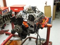
Here's the unit with the engine installed.
20131101-01-EngineStand-800x600_zps1108597a.jpg


Built from:
2" diameter pillow block bearings - eBay - $57
1-20131009-PillowBlockBearing_zps97abbf9d.jpg


Gear reduction box - eBay - $75
2-20131009-RightAngleGearBox_zps29e7ba13.jpg


50 turns on input = 1 output revolution
3-20131009-GearCaseTag_zps6e2ef3f8.jpg


Shaft turned from solid rod to slip-fit the pillow-blocks and match output shaft of gear case. eBay $22 for the raw material, machined by a friend for free.
4-20131009-MachinedShaft_zps5b5d0806.jpg


Frame is made from 3" x 1/4" square tubing. This set forms the mounting base for the pillow blocks. I think I made the entire stand out of a single 20' long stick - don't remember how much I paid.
5-20131009-WeldofBearingBlock_zps5a419696.jpg


Mounting central column to bearing support block.
6-20131009-BearingMountonUpright_zpse43b3e7c.jpg


I installed the machined shaft in the bearings and set them on the tubing before I welded it together. Made sure that the shaft rotated freely.
8-20131009-ShaftInstalledinBearings_zps95cd3130.jpg


For the "feet" of the stand, I used a large hole saw in the drill press to cut away the bottom of the tubes to create feet to mount the stemless casters (also sourced from eBay). I like having the bottom of the stand as close to the floor as possible - just looks cleaner to me. Note - this was absolutely awful work. Even with the slowest speed on my 17" drill press and cutting fluid it took HOURS to cut 8 places on 2 tubes. This is when I wished I had a plasma cutter - would have been 10 minutes effort...
9-20131009-JawHorse_zps236b4941.jpg


Made up another frame to support the gear case.
10-20131009-GearCaseonStand_zpsfa42643f.jpg


skipping forward a bit - this is the shaft-bearing-gear case installed - with a lovejoy coupling between the gear case and the shaft.
19-20131009-GearBoxwithCouplingsandBearings_zpsfde27bfa.jpg


Added some stablizer feet inboard of the casters at each corner. Casters came from eBay - 8.45 each. McMaster-Carr for the swivel feet, 3/8" (or is it 5/16") all-thread and cast knobs. This does a great job of completely stablizing the unit for work on the engine, and also prevents the casters from flat-spotting. The actual lifting point for the levelers is a weld-nut on the bottom of the tube. The rubber pads on the swivel feet didn't last long - the weight of the engine and stand assembly caused the rubber to stick to the floor and they detached the first time I moved the stand. No matter - don't need the rubber anyway...
20-20131009-CastersandStabilizers_zpse3445869.jpg


Added a nice wheel from McMaster-Carr - made the handle from a bolt and a piece of brass pipe.
21-20131009-Handle_zps8bccad6d.jpg


I made the mounting frame for the engine from 1/2" plate. Used the bell housing from the transmission to transfer the position of the holes to bolt to the block. The mounting frame attaches to a 6" square piece of the same plate that was first bolted with a 3/4" grade-8 bolt to the shaft to maintain geometry so I could weld the plate to the shaft.

The only problem I had with this assembly was I failed to consider the balance point of the engine. In the picture of the hand wheel, you can see the adapter is bolted to the drive plate near the center of the adapter.

Like an idiot, I assumed it was the middle of the adapter plate. That's not really a problem for the stand, but the spiders that are in the LoveJoy coupling are too soft. As you rotate the engine on the stand, once it gets over-center on the balance point, it wants to flop over.

That creates a lot of stress on the coupling and induces a large scale pucker on the part of the operator.

I solved the problem temporarily by disconnecting the engine and shifting the mounting point for the drive plate on the adapter plate. You can see in the first picture that the adapter plate is far below the center line of the drive plate now.

I need to order a set of harder spiders for the coupling - that should solve the problem.

There are couple of design issues with this attempt. One thing I wish I had done differently was to make the bottom tube longer to put the front wheels out past the front seal of the engine. Then I could add a catch pan below the engine to make for a cleaner disassembly.

There's also a problem with the assembly being ****-heavy when there's no engine installed on the stand. My original order for the gear case was for a far smaller unit, but the vendor had screwed up their eBay store and didn't have the one I wanted, so they sold me this far bigger unit for the same price as the smaller one. All the weight of the case hanging behind the back tube makes it somewhat tippy. If I had put the front wheels out farther, that would have solved that problem somewhat.

Once the engine is off the stand, I'll weld a "kick stand" of sorts to the back tube to stop it from tipping forward. That, or I'll cut the front wheels off and add some tube to the base to extend the wheels forward...

I think I have less than $400 in the entire assembly.

This was my first heavy-duty welding project and I quickly learned that weld burn is no joke. I wore a welding jacket, but it was hot, so I didn't button it up to the neck. I got pretty serious weld burn on any exposed skin...
 

Hesketh

Well-known member
Joined
Oct 21, 2011
Messages
217
Location
Scotland
wbrian63 That is a hefty stand for sure. Lots of ingenuity on display. Hope mine comes in as nice as yours. Thanks for posting.:beer:

what he said :) Got to say that is including a lot of nice bits like the stabilising feet always handy when you need to start yanking on that bolt that will not quite move.
 

wbrian63

Well-known member
Joined
Mar 31, 2010
Messages
843
Location
Houston, TX
oh gosh - now I'm blushing....

I can't really take credit for the design. I adapted and adopted some features from several I'd seen built on other internet forums.

The one I particularly liked was made by some friends in Australia. They used aluminum tubing, and the engine hung directly off the shaft from the gear case.

I have no idea what type of gear case would have the lateral strength necessary to support a engine (theirs was designed to hold an MB V8 engine in the same family - M100 - as my 6.9, so it's massively heavy as well) - but I figured it was out of my desired spending range. That's why I punted for the pillow block bearings.
 
To avoid these ads, REGISTER NOW!
Top Bottom