To avoid these ads, REGISTER NOW!

Help Me Wire My Garage!

nolimits76

Well-known member
Joined
Jul 11, 2013
Messages
959
Location
Oklahoma
I moved into a new place a few months ago. One of my priorities is getting some additional receptacles and lighting added. I know very little about electricity and codes, so I could use some help.

Attached is a drawing showing my garage. I have tried to mark up appropriately to give a better understanding of what is existing and what I want to add.

Can you guys point me in the right way of what I need to be looking at, size and type of wire, etc? Also, maybe what this would cost to have a contractor do it for me vs trying to self perform what is possible.

=============

Drawing Legend:

- Red circles = Existing 110v outlets (2 are in ceiling for overhead door opener);

- Red rectangle = Existing electrical panel (recessed, finished drywall + paint)

- Green diamonds = Existing light (simple socket - 60w bulb exposed)

- Green arrow = Switch that controls both lights

- Blue square = Existing overhead door opener (3rd bay does not have one installed yet)

- Purple circles = Future 110v outlets I am thinking about adding.

- Purple star = Future 220v outlet(s) I would like to add for future compressor or welder (don't have either currently)

- Orange rectangle = Future Lithonia 4' T8 light fixtures from HD, or similar.

- Orange arrow = Future light switch. With the man door here (barely noticeable in drawing), you have no idea how many times I have cussed the builder for not putting this switch in already. Additionally, I want it wired so I can control the single car and double car bay lights separately. I want the same thing mimicked on the existing switch.

- Pink dashed line = I have a beam that comes down about 14" from the ceiling. Otherwise, this is a clear path between the two areas.

Garage2.jpg
 
To avoid these ads, REGISTER NOW!

Mustang51js

Well-known member
Joined
Jan 24, 2014
Messages
1,734
Location
Haskell nj
What's above the garage,do you plan on removing any Sheetrock. 12-2 romex for outlets and 14-2 romex for lights if you plan on running wires behind Sheetrock. You could do pipe all around. Either way it's a decent amount of work. I would do two possible three circuits for the outlets and one for the lights. Maybe throw a 3way switch for the overhead lights also
 
OP
N

nolimits76

Well-known member
Joined
Jul 11, 2013
Messages
959
Location
Oklahoma
I'd prefer not to remove sheetrock -- walls and ceilings are finished and painted.

This is a single story home, so only thing above is attic space. There is an attic ladder access point near the 21' dimension of the front wall. Directly above the 2 car space a good portion is decked with 1/2" OSB. No decking over the 3rd car bay.

I don't have a problem removing (and replacing) the existing decking. Last weekend, I moved some stuff up to the attic and wasn't impressed with the strength of the existing OSB. I plan to replace with 3/4" plywood.

While up there I also noticed they put up some boards to prevent the insulation from getting blown in over the garages. So that might make it easier to wire initially. But after all that is done I'd like to insulate and put down the new decking.
 

Mustang51js

Well-known member
Joined
Jan 24, 2014
Messages
1,734
Location
Haskell nj
I would use the romex then,the hardest thing you will run into is trying to drill down the wall where the roof rafters meet the top of the walls, you can barely get in there to drill. You could also run pipe up from each outlet and stub it up to the attic,they make connectors to go from romex to pipe so you don't need a box,just make sure you strip the romex outer insulation back so it's not all in the pipe. It's not a hard job just time consuming because of the Sheetrock. In the Attis you would drill holes and run it under the boards. You can also run over the ceiling rafters if you keep it along the edge closer to outside wall, three feet from the outside is inaccessible space. I'm talking space where roof and ceiling meet again.
 

pattenp

Well-known member
Joined
Jun 4, 2008
Messages
10,175
Location
Virginia - USA
Will you clarify how you're saying to go from NM to pipe without the use of a junction box?

Edit: If you are talking about this connector, you are not to strip off the NM-b sheathing. The sheathing needs to stay on when running NM-b in conduit.

361146-ProductImageURL.jpg


.........................,they make connectors to go from romex to pipe so you don't need a box,just make sure you strip the romex outer insulation back so it's not all in the pipe.......
 
Last edited:
OP
N

nolimits76

Well-known member
Joined
Jul 11, 2013
Messages
959
Location
Oklahoma
What size/type of wiring should I be using for the 220v outlet?

Also, what circuit sizes for 110 outlets, 220 outlets and lighting?
 

pattenp

Well-known member
Joined
Jun 4, 2008
Messages
10,175
Location
Virginia - USA
The wire size for the 240V outlets depends on the amp size of the circuit. As already said by Mustang the 120V outlet circuit should be 20 amp with #12 wire. The lighting circuit can be either 15 amp #14 or 20 amp #12, depending on the amp load of the light fixtures that you use.

Edit: 240V, If NM-b (Romex) use #12 for 20A, #10 for 30A, #8 for 40A, and #6 for 50A.
 
Last edited:

Aceman

Well-known member
Joined
Jan 28, 2007
Messages
2,513
Location
Eastern Oregon
Will you clarify how you're saying to go from NM to pipe without the use of a junction box?

Edit: If you are talking about this connector, you are not to strip off the NM-b sheathing. The sheathing needs to stay on when running NM-b in conduit.

361146-ProductImageURL.jpg

I usually staple the romex as close to the pipe as I can and use these:

http://www.amazon.com/dp/B00422M1RC/?tag=atomicindus08-20

You just pound them on the end of the pipe.
 

Mustang51js

Well-known member
Joined
Jan 24, 2014
Messages
1,734
Location
Haskell nj
Will you clarify how you're saying to go from NM to pipe without the use of a junction box?

Edit: If you are talking about this connector, you are not to strip off the NM-b sheathing. The sheathing needs to stay on when running NM-b in conduit.

361146-ProductImageURL.jpg

Yeah that's the connector I was talking about, I will put about two or three inches down the pipe and strip the sheathing off the rest,that was the way I was taught and thought you couldn't run romex inside pipe because of the extra heat it causes with the sheathing on. But yeah that's the connector I call a from-to lol
 

pattenp

Well-known member
Joined
Jun 4, 2008
Messages
10,175
Location
Virginia - USA
NM-b (Romex) can be run in conduit but the sheathing is not to be cut off. The fill for NM-b is figured by using the largest dimension of the cable as the diameter. By cutting the sheathing off of NM-b you are violating the NEC requirements for conductor identifying marking . The conductors inside NM-b have no markings. The markings are on the sheathing.

Yeah that's the connector I was talking about, I will put about two or three inches down the pipe and strip the sheathing off the rest,that was the way I was taught and thought you couldn't run romex inside pipe because of the extra heat it causes with the sheathing on. But yeah that's the connector I call a from-to lol
 
To avoid these ads, REGISTER NOW!

2ManyProjects

Well-known member
Joined
Jul 18, 2013
Messages
757
I moved into a new place a few months ago. One of my priorities is getting some additional receptacles and lighting added. I know very little about electricity and codes, so I could use some help.

Attached is a drawing showing my garage. I have tried to mark up appropriately to give a better understanding of what is existing and what I want to add.

Can you guys point me in the right way of what I need to be looking at, size and type of wire, etc? Also, maybe what this would cost to have a contractor do it for me vs trying to self perform what is possible.

Basic statement about DIY vs. hiring out the job: It will ALWAYS be MUCH more expensive to hire out the job; but that is not the basis upon which this decision should be made. If you are truly comfortable doing something yourself, and FULLY confident in your ability to do it REALLY right, then fine -- go for it. But if you are NOT so confident, then the cost to hire it out will be downright cheap by comparison to the world of hurt which could very easily befall you later, such as in the form of a denied insurance claim or the inability to sell your house.

Drawing Legend:

- Red circles = Existing 110v outlets (2 are in ceiling for overhead door opener);

I'm guessing these are NOT on their own circuit, and whatever circuit they are on is "shared" with some other loads inside the house proper? If so, you probably want to sever that connection, and put ALL of the garage outlets on their own circuit(s), fed directly from the service panel.

- Red rectangle = Existing electrical panel (recessed, finished drywall + paint)

Give us some more details on this. Is this the main/sole panel for the whole house, or a sub-panel? And if the latter, what and where is the main panel? Either way, what is the total capacity of this panel, in terms of both ampacity and branch breaker slots? And how many of those branch breaker slots are currently unoccupied?

- Green diamonds = Existing light (simple socket - 60w bulb exposed)

These will be abandoned/removed. You MAY be able to salvage some of the wiring; but it's surely not worth trying very hard to do so.

- Green arrow = Switch that controls both lights

This too will surely be changed out. To what remains to be seen; but it will probably involve a multi-gang box. You will also want/need to add switching in other locations.

- Blue square = Existing overhead door opener (3rd bay does not have one installed yet)

When it comes time to select/install that GDO, consider one which mounts off to the side of the door, such as the LiftMaster 8500:

http://www.liftmaster.com/lmcv2/productdetail/19724/liftmaster-products/
GDO-LiftMaster-8500.jpg

GDO-LiftMaster-8500-Installed.jpg


This requires that your overhead garage door(s) has/have torsion-type counterbalance springs (or can be retrofitted with such). But once past that minor hurdle, it makes for a MUCH neater, cleaner installation, without a belt/chain track cluttering up the center of the ceiling. I would also make a point of hard-wiring the GDOs, as opposed to using a plug-and-socket arrangement. After all, the GDOs aren't going anywhere, so there is no need to be able to unplug them; and this neatly-sidesteps the "GFCI vs. Motor" problem.

You MIGHT even consider replacing the existing opener on the two-car side, for the same reasons.

- Purple circles = Future 110v outlets I am thinking about adding.

For your general-purpose 120V outlets, my usual "recipe" will surely suffice: Put one double-gang box every 6-8 feet around the entire perimeter of the space, with each of the two duplexes in that box fed from a different breaker than the other one. In relatively small shops/garages, two 20A circuits will normally handle the whole thing; in larger shops, split it up further as you see fit. Keep the bottom of the boxes at least 49-50 inches off the floor; you'll understand why the first time you try to store a 4x8 sheet of plywood, drywall, etc. And finally, note that at least in anything which might be considered a "residential garage", the NEC now requires that ALL 120V outlets be GFCI protected.

- Purple star = Future 220v outlet(s) I would like to add for future compressor or welder (don't have either currently)

Until you do have those tools -- or at least have a VERY firm idea of EXACTLY what they will be (hopefully down to the make & model) -- this is premature. The wiring requirements for such devices are WHOLLY dependant on the particular devices in question; so you really need to know what equipment you will be using, before you can intelligently decide what is needed to support it. Further, any compressor of more than "middlin'" power/size/capacity will surely need to be hard-wired anyway.

- Orange rectangle = Future Lithonia 4' T8 light fixtures from HD, or similar.

Assuming you are talking about something like these:

http://www.homedepot.com/p/Lithonia-Lighting-2-Light-Utility-Light-3348-2L32W-WRAP/100654395
92eeea00-35d4-4de6-9cd6-11e57dd051fc_300.jpg


http://www.lowes.com/pd_163697-337-WP232RLU_0__?productId=3181895
080083518647.jpg


http://www.lowes.com/pd_336745-13537-336745_0__?productId=3686312
037949005377.jpg


...that is a reasonable choice. But I do NOT like your proposed layout at all. This could easily be a discussion unto itself; so I'll leave the details for later.

- Orange arrow = Future light switch. With the man door here (barely noticeable in drawing), you have no idea how many times I have cussed the builder for not putting this switch in already. Additionally, I want it wired so I can control the single car and double car bay lights separately. I want the same thing mimicked on the existing switch.

As alluded to above, you WILL need a much more ambitious /capable switching system than you have now, and near-certainly more than you're currently figuring on. At the very least, you will want switches for your "walk-through" lighting immediately adjacent to EVERY possible entry point into the space. That includes BOTH sides of both overhead doors, as well as EVERY service door. You may also want to be able to control at least some of your exterior lighting from these same locations. Again, the details can be discussed later. But given the potential complexity involved here, you may want to consider something like Insteon controllers:

http://www.smarthome.com/2477S/Swit...-Remote-Control-Switch-Dual-Band-White/p.aspx
2477sbig.jpg


http://www.smarthome.com/2487S/Keyp...pad-with-On-Off-Switch-Dual-Band-White/p.aspx
2487sbig.jpg


- Pink dashed line = I have a beam that comes down about 14" from the ceiling. Otherwise, this is a clear path between the two areas.

As long as you have decent access to both areas from above, this doesn't matter.

I'd prefer not to remove sheetrock -- walls and ceilings are finished and painted.

Given the scope of this project, you really need to resign yourself to AT LEAST cutting some access holes to aid fishing wires, and then patching them later. This is not as difficult or onerous as it might initially seem, as long as you do it right.

This is a single story home, so only thing above is attic space. There is an attic ladder access point near the 21' dimension of the front wall. Directly above the 2 car space a good portion is decked with 1/2" OSB. No decking over the 3rd car bay.

This is all good. Yes, you WILL want to insulate later; but get ALL of the electrical done first.

What size/type of wiring should I be using for the 220v outlet?

As noted above, until you really KNOW which specific compressor and which specific welder you'll be using, there is no way to accurately predict this. If you insist on "pre-wiring" for equipment that has yet to be selected, the ONLY prodent approach is to generously oversize EVERYTHING to a level well beyond what you "think" you might need.

Also, what circuit sizes for 110 outlets, 220 outlets and lighting?

For your general-purpose 120V outlets, use 12-2(w/g) Type NM-B. If the runs are obscenely long (which I seriously doubt is the case here), that can be upgraded to 10-2(w/g) Type NM-B; but this is near-certainly NOT necessary.

For the lighting, you will likely want to use two 15A circuits, based on 14-2(w/g) Type NM-B. This suggestion applies even if, purely from a load perspective, you could get away with one circuit. The point is, if/when one trips (or must be shut down for maintenance), you won't be left totally in the dark.

 
Last edited:

dwm

Well-known member
Joined
Aug 28, 2010
Messages
861
Location
Southeast Michigan
I had to make some similar decisions when I bought my home in July. And I was originally going to add more fluorescent lighting to the existing four sets of 2-tube 8' T12HO lights.

I changed my mind for a number of cons to more fluorescent fixtures. One was power consumption for day-to-day use. I could have addressed some of this by adding more circuits and switches, but it wasn't going to be easy since all the electrical in the ceiling comes through the top plate of a fire-barrier wall with very difficult access. And with 7 gangs of switches already on the wall near the door to the house, I wasn't thrilled with adding more.

A second consideration was noise. The existing ballasts were quiet in terms of emissions, but audibly noisy. I replaced those ballasts with electronic 0F ballasts, knowing they'd be worse in terms of RFI but they're audibly silent and instant-on at 0F.

I'm also one of those people with a bad tendency to swing something long toward the ceiling and break a light.

I wound up adding 24 air-tight recessed housings with Cree BR30 5000K LED bulbs for my day-to-day lighting. Initially I thought I'd still need the fluorescents for real work light, but it turns out that I haven't turned them on but maybe 3 times in the last 6 months. If I were doing this again, I'd add some more recessed cans and ditch the overhead fluorescents. The LEDs are silent in every way, use very little power, and instant-on regardless of temperature. Yes, pricey outlay up front at $19 per bulb. But they'll last a very long time and with all of them on I'm only at 228 watts. I have them on a Leviton OSC20-M0W with OSP20-D0 occupancy sensing setup, and I LOVE it. My garage is a shallow 4-car, and it's so nice to come home and open one of the 16' doors and have the whole garage light up without touching a switch. Previously I did this with a UGDO and HomeLink stuff, now it just happens from motion. I particularly like this when I enter the garage from the stairwell to the basement; there are no switches near that door, but as soon as I enter the garage from the basement the lights come on.

I still have 4-tube T8 fluorescents for task lighting over benches (3 of them), and of course the work lights for under-car work. But my initial requirement of keeping the T12HO on the ceiling was misplaced. I don't NEED them, they're just auxiliary at this point. Given that their total power consumption is over 880 watts, I'm happy I haven't needed them for day-to-day use.

I did still have to deal with the difficult access to the top plates of the fire-barrier wall, but it was minimal. I added a pair of 20A circuits. I've replaced most of the old outlets with GFCI so that now all accessible 120V outlets in the garage are on GFCI. Two of the outlets are now the Hubbell units with 3.0A USB charging ports; those are very handy for keeping my cell phone charged in the garage while I'm wearing a Bluetooth headset (which gobbles phone battery). They're not cheap, and I've never seen the 20A ones locally (have ot be ordered online), but as of right now they're the only ones on the market that will deliver 3 amps on each USB port. Sort of future-proof (I don't have any devices that will draw more than 2.1 amps).

I replaced all of the toggle switches (9 of them) with Leviton 1221-0LC industrial grade toggles. They're lighted when off, which is handy. More importantly for me, they're rated for at least 50,000 cycles. Two of these enable/disable my garage door openers, so I wanted switches I could count on handling motor start-up current for many years. The previous owner had used cheap Decora-style switches here. One had died (roasted contacts), the other was intermittent. I like being able to disable one or both garage door openers. Ever leaned something against the garage door while working and had your significant other come home and hit the garage door opener from his/her car? Or done it to yourself?
 
Last edited:
OP
N

nolimits76

Well-known member
Joined
Jul 11, 2013
Messages
959
Location
Oklahoma
Wow, thanks for all the great info guys -- much, much appreciated. :thumbup:

In regards to some of the items, see below:

1. See pictures below. Panel is recessed. It's the main panel -- no sub-panels exist. Power feeds through outside garage wall (brick) to inside wall (sheetrock) where panel is located. Panel and circuit manufacturer is Square D. Service is 200 amps. And I have 5 free slots open for new circuits.

2. Not sure if you can tell in the pictures above, but I have 3 circuits labeled "garage recepts" -- 17, 19 & 25. Given the limited number of receptacles, I'm certain they are shared to some degree but I haven't did a test to know specifics. If by some small miracle, they are truly garage receptacles only I was thinking maybe I could just use these existing circuits and divide the loads out appropriately between the 3 circuits. Does that sound reasonable?

3. Love the linked switches! I definitely will be going with something like that. It keeps it to a single gang which I prefer. Have you actually used them? Any special quirks or wiring secrets? If you want 4 lighting "zones", how would you go about wiring?

4. I've seen the Liftmaster 8500's and really like the idea of them. Currently I have a Liftmaster 3850 belt drive on the 2 car bay and don't really like it. To me, it sounds like it struggles to get the door up/down. I think it's smart to pre-wire for these -- thank you!

5. I'm okay with minor sheetrock repair/patchwork. I just wanted to be clear my garage wasn't studs only and I didn't want to redo a ton of work if it could be avoided. If things become unreasonable, I am open to exposed conduit, but only as a last resort.

6. I can start a new thread for lighting discussion, but am curious your thoughts on a better light configuration. Is it based on install ease, better lighting, etc? Here are the lights I was looking at, although nothing is set in stone. Overall goal is economical, but quality and durability to last.

http://www.homedepot.com/p/Lithonia...Grey-T8-Strip-Fluorescent-1242ZG-RE/202052422

http://www.lowes.com/pd_163723-337-8TSNF-232-UNV-EB81-U_0__?productId=3181905&Ntt

7. Also, I am curious about the can light layout. Can you share a diagram or picture of how you configured it? I'm curious spacing, exact can light model, etc. The attractive thing is my garage only has 8' ceilings so saving a few inches would be nice.

8. In regards to my 240 outlets, I just thought it would be easier to do when I'm messing with everything else. I don't mind spending a little more and upgrading for worst case scenario. At least I'd be covered. And likely, I will look for a bargain and strike when that is find which makes it almost impossible to accurately predict specifics at this point. What is a good safe wire and circuit size? 6 gauge, 50 amp?

9. Last, but not least -- the DIY vs hired out thing. If I'm being honest, I'm probably in a little over my head. My saving grace is I have friend that is an electrician that I could call if I get jammed up. Hell I could probably call him and he'd do it all for me, but he is changing career paths and I don't want to do that except as a last resort. I was just curious a ballpark of materials cost vs hiring a sub. For instance, if it's $500 for materials and DIY vs $1,500 to have it done -- well, that might be money well spent for me. If it's $500 vs $5,000, then I would probably be more inclined to go DIY. I guess I should check my local codes. The last house I owned, I could do electrical as long as I lived there a minimum of 2 years after it was completed/inspected; otherwise, a licensed electrician had to perform. I'm in a different (more strict) county now and haven't yet checked that.

elec1.jpg


elec2.jpg


elec3.jpg
 

Mustang51js

Well-known member
Joined
Jan 24, 2014
Messages
1,734
Location
Haskell nj
Figure two rolls of 12-2 romex is around $75 each, those lights are around $20-30 each. If you start going with all those smart switches it will bring the price up. I can see you keeping it under $500 if you DIY,hiring someone would prob be like you said $1500-$2500
 
Last edited:

dwm

Well-known member
Joined
Aug 28, 2010
Messages
861
Location
Southeast Michigan
Diagram of my lighting layout attached. Yes, I document my plans before executing them; I didn't create this just for this thread. :)

Recessed cans are the yellow circles, they're Halo H7ICAT. I ordered cheap Halo ERT707WHT trim ring / baffle sets online because it was much cheaper than alternatives and I don't need a fancy baffle in the garage. The ERT707WHT have metal baffles and that's mostly what mattered to me. Long yellow rectangles are the existing T12HO fixtures that I essentially never use. The three other yellow rectangles are 4-tube T8 shop lights over workbenches. Pink lines are the trusses. Black rectangle near one of the T12HO fixtures is the pull-down staircase for attic access. Pink rectangles on the edge are my two 2-car garage doors.

I was fortunate that my attic was clear when I started. It's now ready for insulation which I'll be doing this year after the natural gas heater is hung.

for myself and my significant other, I considered cars in my lighting layout. Many make the mistake of putting their main lighting in position without considering whether or not a tall vehicle is going to block most of the light. Even if you don't put recessed cans everywhere, they're terribly nice to have near walls where a car door will be opened. Reduces the odds of door dings, and lets you find stuff on the floor between the car and the wall. I have put them in my last 2 garages. 18 to 24 inches from the wall so you still have room for say ClosetMaid Maximum Load shelving without blocking the light. The previous owner's positioning of the T12HO fixtures was poor when the garage was occupied with vehicles, but I left them there because I didn't want to rewire them for what has become rarely used auxiliary lighting. I thought I'd change my mind about using them when woodworking, but I haven't needed them. Mill and other tools have task lighting

The OSC20-M0W is probably the best investment I've made in a long time. While it's on a light switch, I never use the switch. Once adjusted, it just works. Lights come on when I'm in the garage, don't turn off on me when I'm in there, and don't turn on when ambient light is sufficient (adjustable). My significant other likes the fact that the garage lights up fully when the garage door is opened and doesn't turn off until she's already in the house, no matter how long she lingers in the garage. Positioned correctly, it covers the whole garage, including the far reaches. While my GDO has a motion sensor, its range is poor, especially off-axis.

EDIT: attachment too big. Link:

Garage Lighting Layout
 
Last edited:
OP
N

nolimits76

Well-known member
Joined
Jul 11, 2013
Messages
959
Location
Oklahoma
Mustang51js, thanks for confirmation on the pricing. Sounds like I am in the ballpark. Even if I hire this out, at least I will know what they should be quoting. It will help me better analyze their quotes.

dwm, that is awesome. Thank you!!! Any chance, you have any pictures of the actual space? Just curious what it looks like compared to traditional fluorescent lighting in a real environment.
 

dwm

Well-known member
Joined
Aug 28, 2010
Messages
861
Location
Southeast Michigan
I have not taken many pictures, I've been spending my time working on the garage and the rest of the house (it was a foreclosure, not in great shape). The only two that have any hint of the new lighting... one from when I was in the process of rejointing all of the ceiling drywall. Not fun in a non-empty garage. Baffles and trim rings were not installed at this time.

0695.jpg


And another not long after when I was installing shelving and preparing to install stainless steel pegboard.

0754.jpg


No big-picture photos yet, I probably won't take any of those until the spring. Winter here has been brutal this year and I don't open the doors any more than I absolutely must.
 

2ManyProjects

Well-known member
Joined
Jul 18, 2013
Messages
757
Wow, thanks for all the great info guys -- much, much appreciated. :thumbup:

In regards to some of the items, see below:

1. See pictures below. Panel is recessed. It's the main panel -- no sub-panels exist. Power feeds through outside garage wall (brick) to inside wall (sheetrock) where panel is located. Panel and circuit manufacturer is Square D. Service is 200 amps. And I have 5 free slots open for new circuits.

That's all good, except maybe the part about having only five open branch breaker slots available. That's not a whole lot for a "generously" equipped garage. If you figure two circuits for your general-purpose 120V outlets, and two more for your lighting, you no longer have room for even one dual-pole 240V breaker for a compressor, or a welder, or whatever.

2. Not sure if you can tell in the pictures above, but I have 3 circuits labeled "garage recepts" -- 17, 19 & 25. Given the limited number of receptacles, I'm certain they are shared to some degree but I haven't did a test to know specifics. If by some small miracle, they are truly garage receptacles only I was thinking maybe I could just use these existing circuits and divide the loads out appropriately between the 3 circuits. Does that sound reasonable?

I strongly suggest that you put some serious effort into tracing out those circuits and identifying ALL the loads on them. For that matter, it would be a good idea to do this for ALL the branch circuits, on general principles: Make up a "cheat sheet" using your word processor or spreadsheet program, unambiguously identifying and listing EVERY individual load on every breaker, then print it out and tape it to the inside of the panel door. You'll thank yourself 1,000 times over in the future.

Anyway, getting back to the topic at hand, depending on exactly what you find, you MAY be able to "free up" at least one or two of those existing breakers so that they can indeed be dedicated to the garage; and that in turn might make all the difference in terms of having "enough" circuits, and thus being able to avoid the need for a sub-panel.

Note that this MAY involve re-assigning some of the loads among the various existing breakers (especially if you currently "share" one or more breakers between house loads and garage loads). The specifics of this can get complicated in a hurry, and are completely dependent on just what the existing situation REALLY is; so I won't go into much more detail here, save to say that there IS a "right way" and a "wrong way" to do this (which means, firstly, NEVER "double up" multiple branch circuit wires on a single breaker).

OTOH, it MIGHT be simpler/easier to just go ahead and install a sub-panel, and be done with it.

3. Love the linked switches! I definitely will be going with something like that. It keeps it to a single gang which I prefer. Have you actually used them?

I started out with X-10 many years ago, but got frustrated with the **** quality control and general lack of reliability. I'm just now transitioning to Insteon, in both houses (the Shore house will likely get done first, as I am in the midst of re-doing it post-Sandy).

Any special quirks or wiring secrets?

Not really. It's designed for easy retrofitting; so all "conventional" wiring techniques are still appropriate. That said, if you KNOW going in that you're going to be using Insteon, the wiring can actually become simpler, particularly as compared to conventional "3-way" and "4-way" switching setups.

If you want 4 lighting "zones", how would you go about wiring?

Any light (or group of lights) that you want to INDIVIDUALLY control requires a load controller, such as the aforementioned wall switch or keypad OR a hardwired control module such as:

http://www.smarthome.com/2475SDB/In...ontrol-In-Line-On-Off-Switch-Dual-Band/p.aspx
2475sdbbig.jpg


which can be hidden away out of sight.

CONTROL modules (such as, again, that wall switch or keypad) can be placed anywhere, and need only a simple two-wire (plus ground, of course) connection to the main electrical system. They do not NECESSARILY need to also be connected directly to a load (tho' of course they can be, if also being used as load controllers, which is often the case).

Once everything is wired up, you create "virtual links" between the various devices via a series of one-time button-press sequences. Once that is done, these "links" are stored in non-volatile memory, and do not need to be repeated (unless you want to change something, of course). These "links" can be both "overlapping" and "redundant" to some degree, as desired; hence you can establish various "scenes", each of which get activated with a single button-press.

4. I've seen the Liftmaster 8500's and really like the idea of them. Currently I have a Liftmaster 3850 belt drive on the 2 car bay and don't really like it. To me, it sounds like it struggles to get the door up/down.

That shouldn't be. IIRC, the Liftmaster 3850 is rated at 3/4 HP, which should be more than enough for even the largest/heaviest residential garage door. I would strongly suggest that you check the balance on your door, to ensure that the counterbalance springs are really doing their job. The GDO itself really should NOT have all that much load on it.

5. I'm okay with minor sheetrock repair/patchwork. I just wanted to be clear my garage wasn't studs only and I didn't want to redo a ton of work if it could be avoided. If things become unreasonable, I am open to exposed conduit, but only as a last resort.

That really shouldn't be necessary; and I, for one, generally dislike the look of exposed conduit, surface-mount switch/outlet boxes, etc., in residential garages. Beyond its propensity to be a world-class dust-catcher, it will near-certainly wind up being "in the way" of something you want to do later, such as mounting wall cabinets or shelving.

6. I can start a new thread for lighting discussion, but am curious your thoughts on a better light configuration. Is it based on install ease, better lighting, etc?

Primarily the latter. As you have it set up in your sketch, most of the light is in exactly the WRONG places -- i.e., directly over the vehicles. Just how often do you need to brightly illuminate the roofs of your cars, as opposed to the areas where you will REALLY be working (which are nearly always around the perimeter of the vehicles)?

Here are the lights I was looking at, although nothing is set in stone. Overall goal is economical, but quality and durability to last.

http://www.homedepot.com/p/Lithonia...Grey-T8-Strip-Fluorescent-1242ZG-RE/202052422

http://www.lowes.com/pd_163723-337-8TSNF-232-UNV-EB81-U_0__?productId=3181905&Ntt

You don't want to use either of those, or anything like them.

Assuming this is a conventional residential garage, your ceiling height is presumably no more than 9-10 feet. Given that, the reflectors on those H.D. "shop lights" are actually counterproductive, as they will effectively restrict the distribution of the light out to the sides of each fixture, causing you to need still more fixtures (each spaced more closely to the next one) in order to avoid spotty uneven lighting. Also, odds are that fixture is NOT rated for direct surface contact, due to heat-disspation issues; hence, they would NEED to be suspended via the supplied chains -- which further exacerbates the light-distribution problem, by lowering the effective mounting height. And finally, you do NOT want to use ANY "plug-in" shop light anyway, because this would require the use of GFCI outlets, which both raises costs AND can create problems (GFCIs and fluorescent loads sometimes don't mix very well).

The 8-foot "tandem" fixtures from Lowe's are SOMEWHAT less problematic, but still far from ideal. You're not really saving any money (as shown previously, suitable twin-tube fixtures can be had for little more than half what these things cost; so you can afford to use twice as many of them). But you ARE giving up quite a bit of flexibility in terms of both fixture placement and switching. In a sense, it's an answer to a question that doesn't need asking. The ONLY thing it has going for it is slightly easier installation, due to needing only half as many electrical connections. But it would be silly and short-sighted to let that tail wag the dog, as it were.

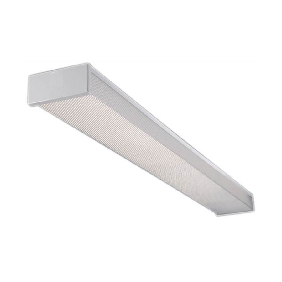
Use twin-tube four-foot fixtures similar to what I cited earlier, and be done with it.

[The BBS software is nattering at me that the message is too long. So I'm breaking it here. Continued in next message...]


2ManyProjects

Well-known member
Joined
Jul 18, 2013
Messages
757
[...Continued from previous message.]

7. Also, I am curious about the can light layout. Can you share a diagram or picture of how you configured it? I'm curious spacing, exact can light model, etc. The attractive thing is my garage only has 8' ceilings so saving a few inches would be nice.

The usual problem with recessed can-type lighting for this sort of application is that they tend to have relatively narrow distribution patterns; which in turn means you need a LOT of those lights in order to provide truly even distribution. The lower the ceiling, the worse this problem becomes. That said, "dwm"'s setup looks somewhat better in the photos than I would really expect, given the layout shown in his diagram; but pictures can be (and often are) misleading. And still, there are some tell-tale signs: Note the alternating light/dark areas along the wall in the first photo, and the sharp shadow lines made by the wire shelving in the second.

The surface-mount fixtures I cited earlier "cost" you only about two to 2-1/2 inches of clearance; and even then, only in a relatively few small areas around the space. Not worth worrying about, IMCO.

8. In regards to my 240 outlets, I just thought it would be easier to do when I'm messing with everything else. I don't mind spending a little more and upgrading for worst case scenario. At least I'd be covered. And likely, I will look for a bargain and strike when that is find which makes it almost impossible to accurately predict specifics at this point. What is a good safe wire and circuit size? 6 gauge, 50 amp?

Both compressors and welders have "special" rules which need to be used when sizing the circuits to support them. That said, if you're willing to throw more money into materials than is likely "really" needed, it can't hurt to generously oversize both circuits. AWG 8 type NM-B (or AWG 10 Type THHN in conduit; but forget that, for the reasons cited above) will support up to a 5 HP compressor. However, note that for anything above 3 HP, the compressor WILL need to be hard-wired, as opposed to using a plug/receptacle arrangement; if you want to pre-wire, you can put in a junction box and cap it off with a blank plate for the time being.

Dedicated welder circuits are "permitted" to use somewhat undersized wiring, due to the typically low duty cycle of such devices. That said, the key words in that statement are "dedicated" and "permitted" -- nothing says you MUST undersize the wiring; and there is a fair argument to be made in favor of NOT doing so.

And remember, each of these circuits will require a dedicated two-pole breaker in the panel -- that's four "slots" burned right there.

9. Last, but not least -- the DIY vs hired out thing. If I'm being honest, I'm probably in a little over my head. My saving grace is I have friend that is an electrician that I could call if I get jammed up. Hell I could probably call him and he'd do it all for me, but he is changing career paths and I don't want to do that except as a last resort.

In which case, the FIRST thing I'd do is take you buddy out for a few beers (on your tab), and pick his brain. Get HIS honest opinion of your skills and qualifications. Perhaps you can make a deal where he will "look over your shoulder" while you do most of the "grunt work", with Carte Blanche to smack you upside the head whenever you screw up; then when that is all done and passes (his, informal) inspection he comes by to make the final connections and makes sure everything is ready for the real (official) inspection.

 
To avoid these ads, REGISTER NOW!
Top Bottom