To avoid these ads, REGISTER NOW!

Help Request: Wiring Lighted Rocker Switch to Bench Grinder

apittmanii

Well-known member
Joined
Dec 28, 2015
Messages
110
The on/off switch to my 120 volt bench grinder stopped functioning. The old switch (Photo #1) had 2 quick connect terminals that simply interrupted / connected the hot (black) wire to the bench grinder. I purchased a new switch with a 125 volt neon lamp that I would like illuminated when the grinder is “on.” The new switch has the following markings:

McGill Model 0851-1301
SPST On/Off Rocker Switch
15 AMP
3/4 HP 125-277 V.A.C.
Neon LAMP 125 V.A.C.

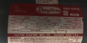
The new switch has 3 quarter-inch quick connect terminals. When hooked up to the two available wires, terminal 1 and 2 (Photo #2) correctly turn on / off the grinder, just like the old switch. Terminal 3 has NO continuity to terminal 1 and 2, regardless if the switch is toggled to the “on” or “off” position. Photo #3 shows the grinder wiring. Photo #4 shows grinder tag / specs.

My question is this: how do I wire this switch so that the lamp illuminates when in the “on” position? What do I connect terminal 3 to?
 

Attachments

  • Photo 1.jpg
    Photo 1.jpg
    147.9 KB · Views: 44
  • Photo 2.jpg
    Photo 2.jpg
    75.3 KB · Views: 47
  • Photo 3.jpg
    Photo 3.jpg
    134.7 KB · Views: 50
  • Photo 4.jpg
    Photo 4.jpg
    124.7 KB · Views: 42
To avoid these ads, REGISTER NOW!

Norcal

Well-known member
Joined
Mar 16, 2008
Messages
13,754
How is the switch terminals marked? One will be Line, then Load, & a neutral for the pilot lamp.
 
OP
A

apittmanii

Well-known member
Joined
Dec 28, 2015
Messages
110
How is the switch terminals marked? One will be Line, then Load, & a neutral for the pilot lamp.

They all say L3. However, I’m fairly certain based on a multimeter continuity test that the two terminals connected to wires in the attached photo are line and load. Are you saying I should pigtail the neutral before it hits the capacitor and attach that to the third terminal on the switch?

Note the original switch (original post photo #1) completely bypassed the neutral wire and only served to interrupt the hot (line/load) wire. Not sure if this has any relevance to the proposed solution.
 

Attachments

  • 6D7D3363-009E-44C8-B92B-26361A74BF5D.jpg
    6D7D3363-009E-44C8-B92B-26361A74BF5D.jpg
    133.5 KB · Views: 37

matt_i

Well-known member
Joined
Mar 14, 2008
Messages
10,728
Location
SE Michigan
How is the switch terminals marked? One will be Line, then Load, & a neutral for the pilot lamp.

Agreed, the only way the bulb can light is to have a connection to the neutral (white, pre-capacitor). The switch, as its wired, breaks only the "hot" leg of the 120vac.
 

dogdog

Well-known member
Joined
Nov 15, 2011
Messages
12,711
just stating the obvious here for you...

For 120V stuff you just have to switch the hot.... the center pin is always the AC in I think.... since you got a neon ... 3 pin, you'll have to figure out which one switch the AC on/off... continuity / ohm test between center and one of then pin would yield 0 and the other should give you some ohm readings... the one that give ohm reading should be the one for the neon lights, (it's not necessary but a luxury)...

If I were to approach this, I would just identify the pin that needed to turn on the motor, make sure it works, the other pin would be for the neon light and you can just connect a neutral to it... from the cap or from the incoming neutral line...( I think it is the same for Neutral)...

you can always google "rocker switch with neon lights diagram" and see a diagram of it... they should be some what universal...

Just as an example... you'll see the neon is in series with a resistor, most of them are... do a ohm test should easily find the pins...

L0419782-01.gif


https://www.eevblog.com/forum/projects/wiring-radioshack-spst-neon-rocker-switch/
 
Last edited:
To avoid these ads, REGISTER NOW!
OP
A

apittmanii

Well-known member
Joined
Dec 28, 2015
Messages
110
Thanks for the feedback. Connecting the neutral to the 3rd tab made the switch function as I wanted.
 

Bert_

Well-known member
Joined
Dec 24, 2016
Messages
9,729
Location
NW Iowa
The meter did not read anything when measuring the 3rd pin because the neon lamp does not conduct at the very low voltage that the meter uses, 9v or less probably.
 

MikeF2316

Well-known member
Joined
Dec 29, 2012
Messages
9,605
Location
Thornhill, ON
The meter did not read anything when measuring the 3rd pin because the neon lamp does not conduct at the very low voltage that the meter uses, 9v or less probably.

Right, neon bulbs need around 90 volts before they "light off". And they are like a solid state diode, in that the voltage across them when they are conducting likes to stay stable, so they are almost always installed in series with a resistor that soaks up the excess voltage. (Of course neon bulbs conduct in both directions, no just one like a diode.)
 
OP
A

apittmanii

Well-known member
Joined
Dec 28, 2015
Messages
110
The meter did not read anything when measuring the 3rd pin because the neon lamp does not conduct at the very low voltage that the meter uses, 9v or less probably.


Thanks - I was wondering about this exact thing, why the meter did not read anything. That’s good to know.
 
To avoid these ads, REGISTER NOW!
Top Bottom