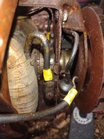
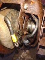
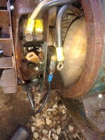
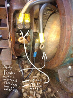
Voltage induced by the spinning rotor to the rings on the end of the shaft, transmitted to the brushes running on those rings, wires attached to brushes on one side and (usually) a voltage regulator/cutout system, and From there to your breaker/outlet/feed lines.
What diagnosis have you done do far? Do you have voltage anywhere in the system while running? If so, what and where? If not you may have broken windings or cooked magnets or ??
I suspect something crapped out (broken winding wiring) and someone dug in trying to "fix it" blind, ergo your wiring issues. You need to see if the genset hooked to the motor is even viable. Your overload protection device could be blown. Your voltage control relay could be shot. Someone could have hooked it to a high draw circuit and cooked it. Your motor brushes may be not making good contact or broken. Or the sptings for them weak or broken. Hell, lots of potential issues. Broken windings in the genset are common in ancient units like this, and (unless your BIL works in a motor shop) usually not worth rewinding, unless you have a particular attacment to the thing (like it's a genset for a particularly rare low amp welder, or it was your father-in-laws, or somesuch). You can be into a newer (and better) unit cheaper.
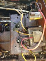
Otherwise - Black=load, White=Neutral, and Bare/Green=Ground. Your red/yellow to transformer to relay is your voltage cutout / control circuitry. The green thing is an overload or short circuit prevention device (and they can and do go to **** with age sometimes). Like Mike said, at 50+ years, a lot of those components and wiring will give you probs.
Get out the old voltmeter, watchout for moving parts and bare wires, and start checking to see what you have where.


 www.harborfreight.com
 www.wincogen.com