To avoid these ads, REGISTER NOW!

Help with Scroll Air Compressor

51dueller

Well-known member
Joined
Feb 22, 2021
Messages
221
Location
Saskatchewan
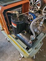
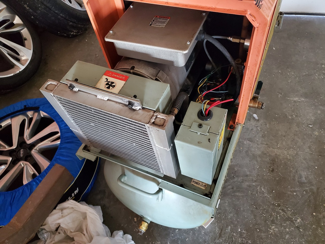
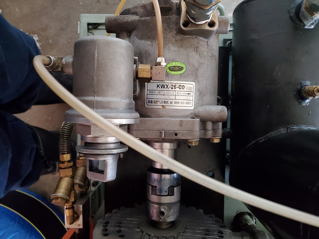
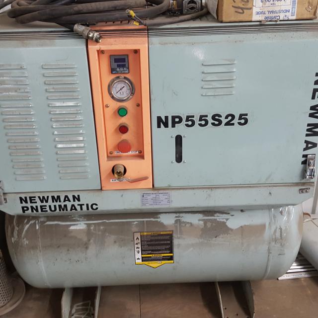
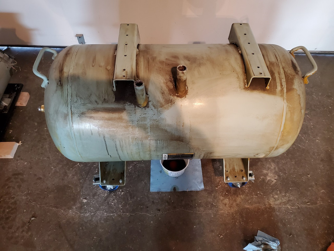
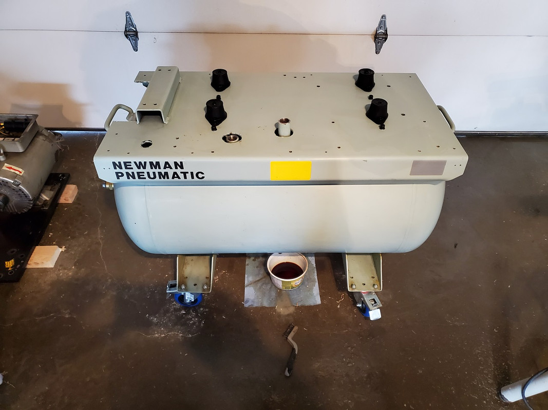
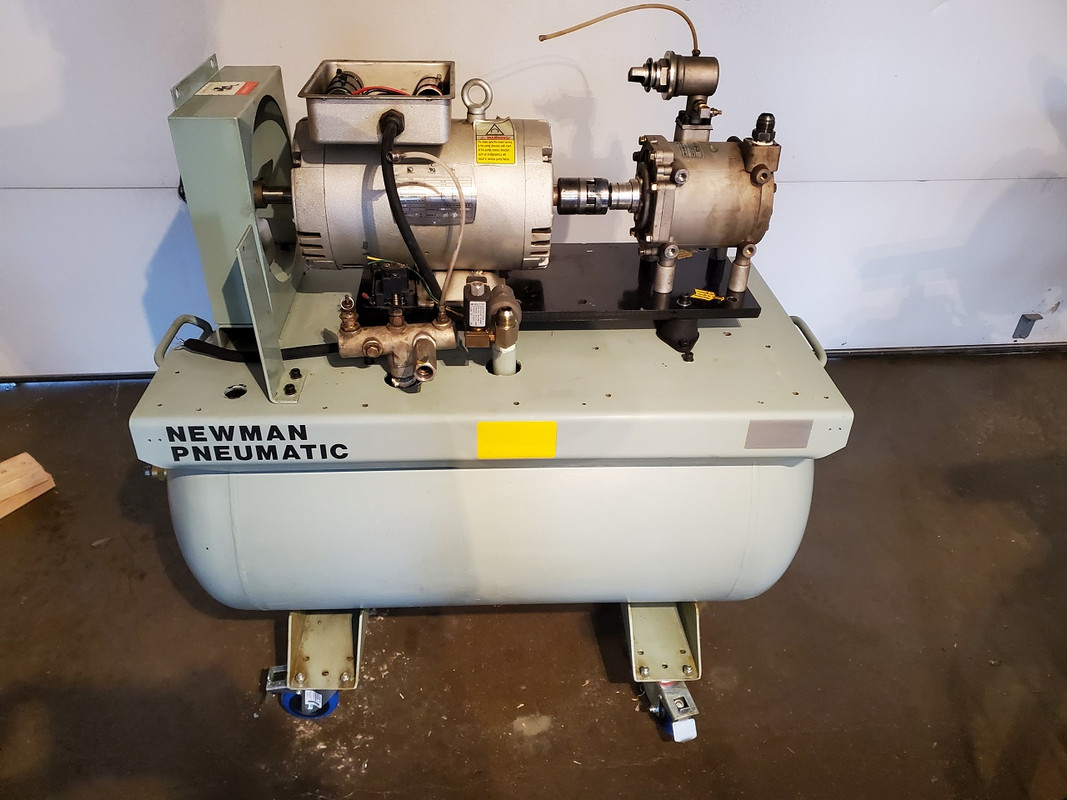
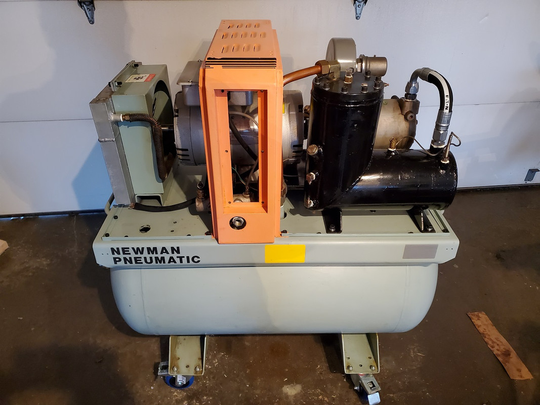
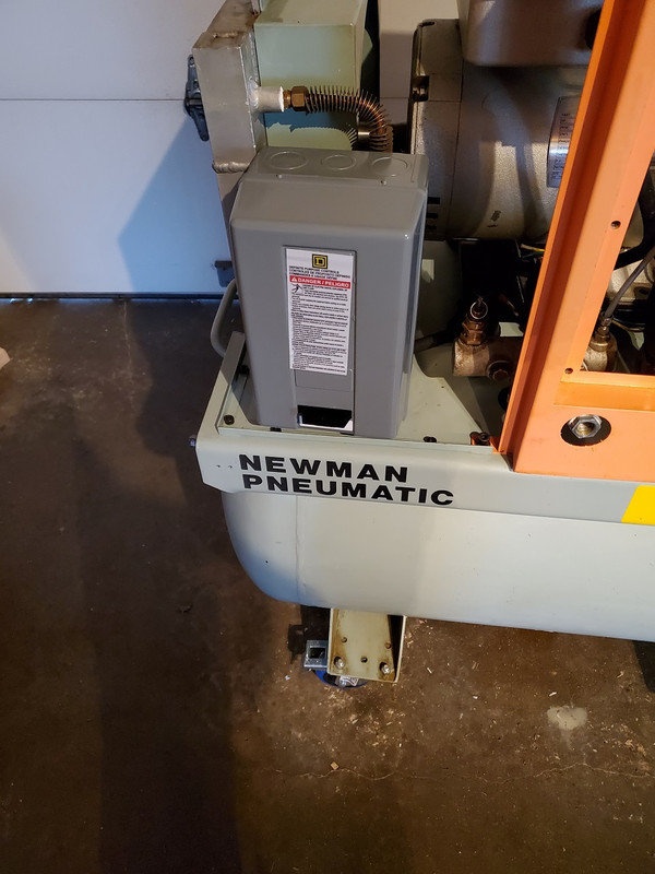
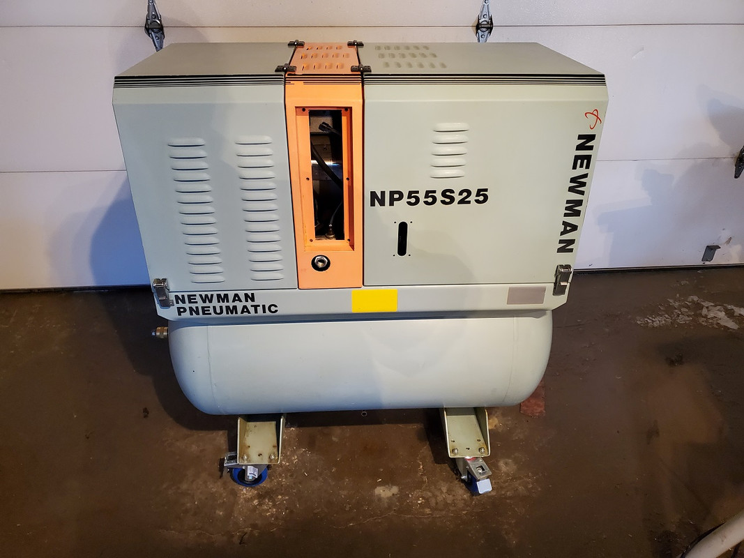
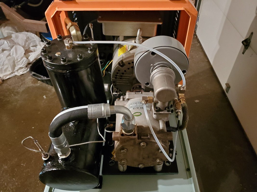
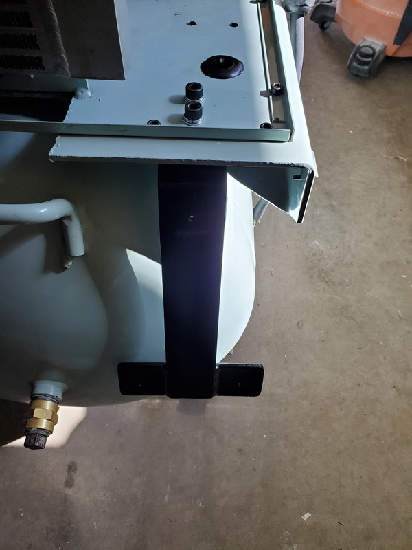
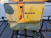
I just recently picked up a used Newman Pneumatic NP55S25 scroll air compressor. It's about 12 years old and most likely of Asian manufacture.
1.jpg
2.jpg
3.jpg
4.jpg
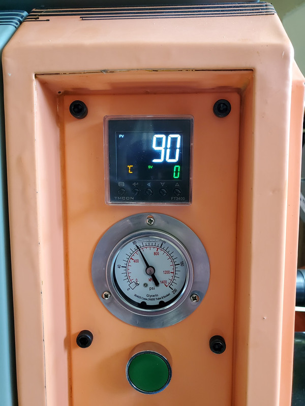
It's a 5.5 HP 3450rpm 220v single phase direct drive motor with 190L tank, 125 psi max pressure and says output is 0.5M3/min which converts to 17.5 cfm. The 7.5 HP version got a oil temperature display and separate on/off buttons. Mine does have the temperature sensor but its not connected to anything.

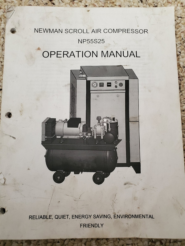
What kind of oil can I use in this thing? The owners manual is unhelpful as it just says scroll air compressor oil and shows a small picture of a gallon jug. I've called around to several big air compressor places but they only know of the oil less ones. Eastwood is the only comparable unit and they don't say what their oil is.

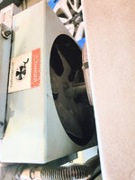
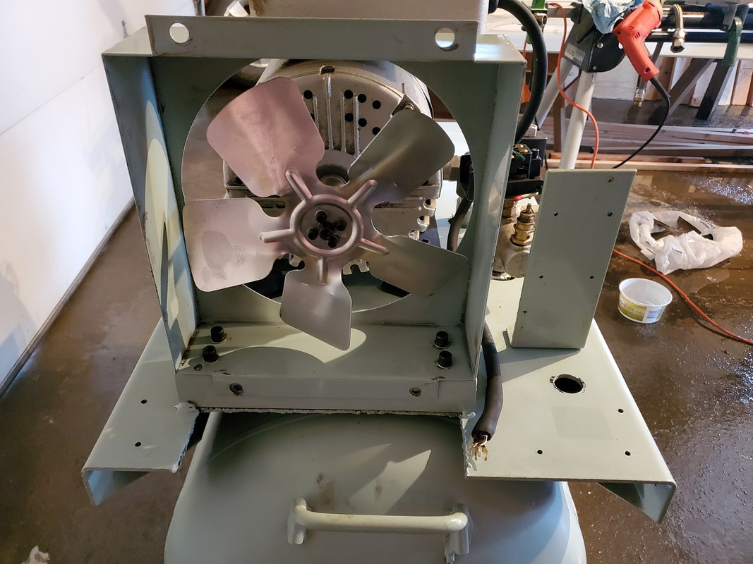
The cooling fan also has some cracks forming on the blades. Where could I find a 9" diameter fan with a 1 1/6" shaft?

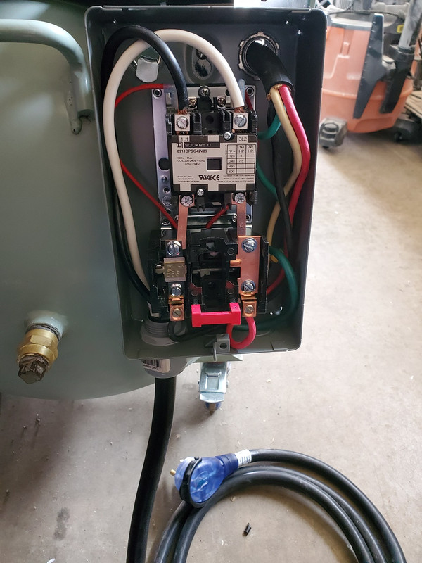
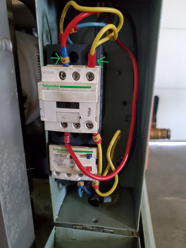
I'm waiting to hear back about getting a new magnetic starter as the original must have died and was replaced with a Schneider relay setup that is normally in an electrical panel. While it "works", its wiring leaves much to be desired.

Any help would be appreciated for this oddball unit.
 
To avoid these ads, REGISTER NOW!

MacMcMacmac

Well-known member
Joined
Oct 21, 2014
Messages
1,591
Location
canada
The only reference to Newman compressors I can find is in Thailand, but I'm not sure if it is related to your machine. See if there is a maker's badge on the tank. It might help you narrow it down. If there is no readout for the temperature, then the temperature probe is most likely a high temperature shutdown which is usually wired in series with the starter coil to de-energize the starter if it the compressor overheats.

MultiWing should make a fan that would suit your needs.

Is that an LED display above the pressure gauge?

Parts are going to be an adventure with this one. I get the feeling it may have been packaged as part of another larger piece of process equipment.

A good AW32 hydraulic oil should work well in this machine.

Keep posting photos and something might ring a bell. I was once able to find the make and model of a compressor from the 50's just from a crankcase part number cast into it.
Interesting find.

Good luck.
 
Last edited:

DeeKay

Well-known member
Joined
Nov 25, 2020
Messages
448
Location
Colorado
Take a picture of that badge on top of the airend.

Is there any contact info in the manual that you have?

According to the SDS, the eastwood stuff is a paraffinic base, but obviously that doesn't necessarily mean that is what this thing is running.
https://www.eastwood.com/images/pdf/31718_Scroll_Compressor_Oil_SDS.pdf

You could take a sample of the oil that's currently in the sump and send it out to get analyzed, that will at least tell you what base stock the oil is.
If it was me I would get some flush fluid for a flooded screw compressor, run it for a while, drain and then run this on a universal screw compressor oil, something compatible with PAG/POE. This would also be a good time to change out that separator element if you can get one.
Hydraulic oil is great at a lot of things, but not great for flooded compressors, it's designed for a closed system that stays relatively clean. Flooded compressors basically force contaminate the oil; anything that's in the air ends up in the oil; oxygen, water, chemical vapors etc. Screw compressor oil has additives that combat all that bad stuff to prevent it from becoming acidic.
 
Last edited:

MacMcMacmac

Well-known member
Joined
Oct 21, 2014
Messages
1,591
Location
canada
If I wanted to flush the machine I'd go with atf and run it for a week or so. Then drop the oil and put in whatever I was going to use. Nothing wrong with any of your advice except finding compressor flush in a small enough quantity not to end up with a several lifetimes supply might be an issue. I never had any problem with running AW32 in a screw. It's cheap and readily available, has decent demulsibility, and can be had in quart bottles. The only oil I would not recommend for a compressor is Nuto. I could always tell when a machine had run it because the inside always had a chalky brown coating and the oil was sludgy as hell.
 
OP
5

51dueller

Well-known member
Joined
Feb 22, 2021
Messages
221
Location
Saskatchewan
The owners doesn't have any contact information.
13.jpg

14.jpg


Here's some more pictures:
7.jpg

6.jpg


There is no asme tag on the tank. The one sticker says it was tested to 189 psi.

Mine doesn't have the temperature display. The sensor currently has a reading of 100 ohms which to me means its a normal variable sensor and not a switch.
8.jpg

The only other picture I can find of one of these compressors is this. This is the 7.5 hp version and it has the lcd temperature display. While it would be nice to have, I don't know it would be worth the expense.

9.jpg

10.jpg

11.jpg

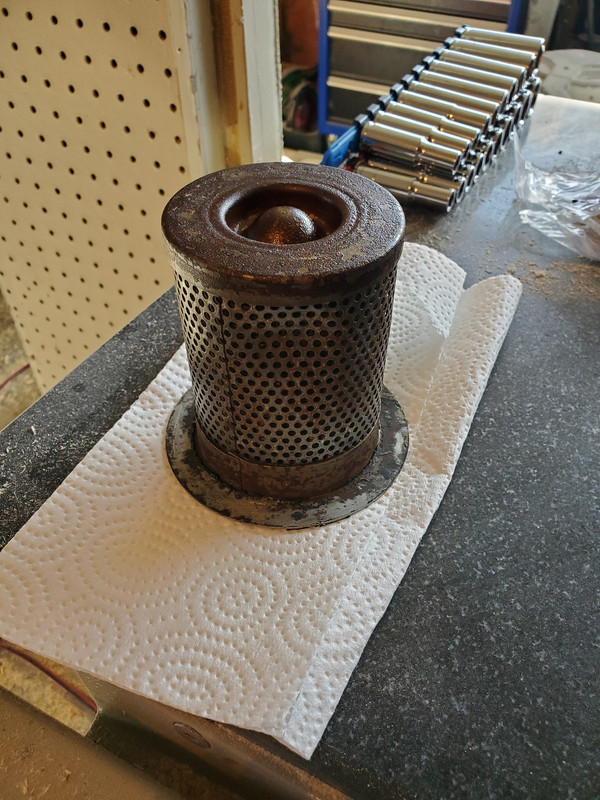
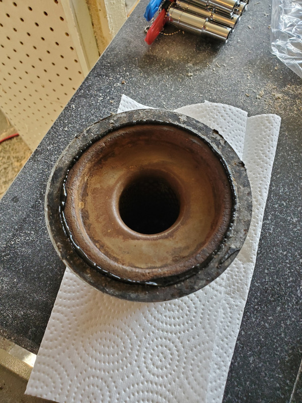
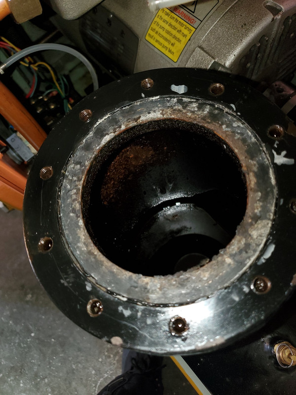
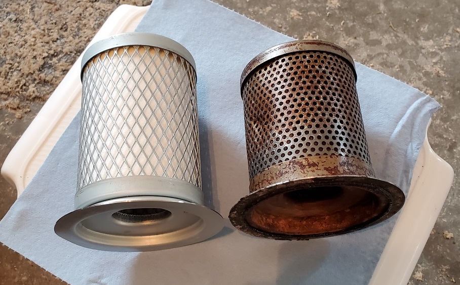
Well the oil separator has seen better days and the oil isn't very clean. It also had been siliconed so it has been apart before.

12.jpg

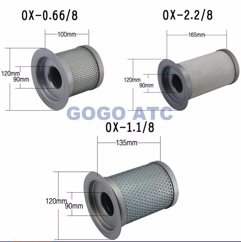
Aliexpress has some scroll air compressor separators that look like they should work. The owners manual says 0.6 separator in the parts breakdown but the 1.1 looks closer in size. Mine is a 120mm flange, 90mm outer filter diameter and 120mm tall. If I do order one, I might as well get two of them.

I was thinking of using screw compressor oil if I couldn't find anything since I know they also run an oil separator like this.

Good thing I only paid $375 CDN for this so it doesn't quite hurt to spend some money on it. A new magnetic starter has been ordered.
 

seber

Well-known member
Joined
May 31, 2016
Messages
4,205
Location
Deep East Tx.
I second the advice to stay far away from hydraulic oil. It is made to be hygroscopic to avoid water separation in a closed system. In an open system that is a recipe for disaster. It can continue to absorb water out of the air until it becomes useless as a lubricant.
 

MacMcMacmac

Well-known member
Joined
Oct 21, 2014
Messages
1,591
Location
canada
Well with no contact info we can be fairly certain they are not the next incarnation of Atlas Copco or Ingersoll Rand.


O1CN01kqRTAm1kaBhVqv19Y_!!1072704699.jpg


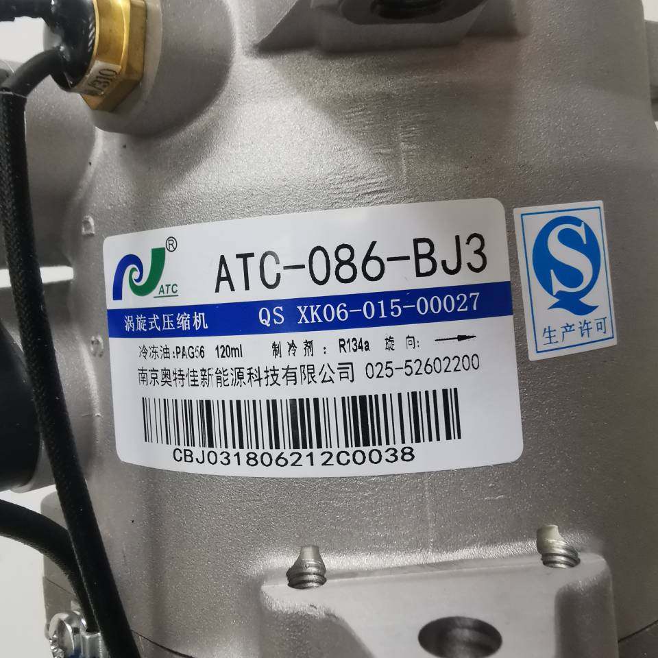
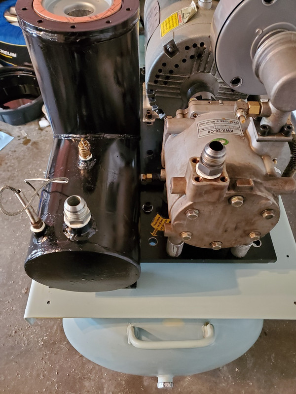
Looks like the air end is a re-purposed ac compressor, or at least, is also used in that application.

https://www.google.com/search?q=qs+...XFlkFHTMaANUQ9QF6BAgIEAE#imgrc=b3iPgg9CptdIbM

This may not be a bad thing really, since ac compressors are designed to run long hours at high pressures in a hot environment at pretty high rpm. York AC compressors are commonly used for underhood air compressors for offroaders to air up their tires before hitting the pavement to head home. At least you know there is a replacement option if the scroll packs it in.

This does raise some questions as to the oil though.

You will certainly need a new separator. If you can supply all the relevant details you might find a company called Keltec makes something you can use if you don't want to go the AliExpress route.

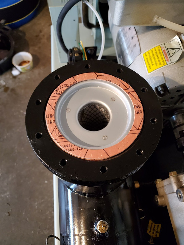
Whichever route you go make sure there is a heavy staple through one of the separator gaskets to ensure an electrical connection between the separator element and the tank to provide a ground. This will dissipate static electricity in the tank which can lead to a discharge and possible fire. Whoever worked on it last disregarded that by the look of things.

Any decent compressor oil will work if you don't want to use hydraulic oil. PetroCanada made some good stuff. I'm not sure if Sunoco still sells lubricants under that brand name. I doubt you'll get less than a 20L pail of it though.

I'm actually kind of impressed by the workmanship of this little machine.

Sounds like you have an RTD sensor there, so you would definitely need some kind of controller to utilize it. There might be an off the shelf Omega digital controller you could slot in there pretty easily.

https://www.omega.com/en-us/control-monitoring/controllers/pid-controllers/cn1a-series/p/CN1A-RTD
 
Last edited:

DeeKay

Well-known member
Joined
Nov 25, 2020
Messages
448
Location
Colorado
That separator looks pretty rough. Also looks like you're missing the inlet filter.

If you measure that square cutout above the pressure gauge it might match a standard DIN size. If that's the case you can just buy a panel mount temperature switch...a lot of these also have universal/configurable input too and are pretty cheap, . You would just need to figure out whether the temp probe is an RTD, thermocouple, NTC, PTC etc.

That's definitely an interesting little air compressor.
 

MacMcMacmac

Well-known member
Joined
Oct 21, 2014
Messages
1,591
Location
canada
I can almost sense enterprising GJers figuring out how to make their own scroll compressors.

I would not be surprised if someone on this board pulled it off. Heck, you could use a piston style pump in the same manner if you wanted to.
 

DeeKay

Well-known member
Joined
Nov 25, 2020
Messages
448
Location
Colorado
I can almost sense enterprising GJers figuring out how to make their own scroll compressors.

I would not be surprised if someone on this board pulled it off. Heck, you could use a piston style pump in the same manner if you wanted to.

If only I had more time and money that would be a pretty fun little project.
Like you said, I'm pretty impressed with how well thought out this little unit appears to be.
 
OP
5

51dueller

Well-known member
Joined
Feb 22, 2021
Messages
221
Location
Saskatchewan
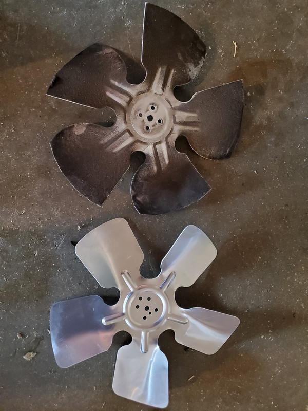
Well they really did continue the HVAC theme as I got my fan blade today.
15.jpg

It's a 10" fan blade for a refrigerator/freezer but it has the correct bolt pattern. I thought it was originally a 9" fan as the parts breakdown said 230mm but once I got it off it was a 10".

Since the weather has been nice, I've got it all disassembled now. It's been taking some scrubbing but the yellow paint overspray is coming off.
16.jpg

Just need more above 0'C temperatures to get more done.

Still waiting on parts. Trying to find anything locally has been useless. Got stuff coming from China, USA and Ontario.
 

ihateminimumwage

Well-known member
Joined
Jan 26, 2012
Messages
3,961
Look into Atlas Copco "Paroil M" or an equivalent for compressor oil. It's what gets used on all the diesel rotary screw compressors we work on that use that same style of separator (Atlas Copco, Sullair, IR, Doosan, Airman, etc).

MacMcMacmac is also correct that AW32 is a common oil rated for compressors as well.
 
OP
5

51dueller

Well-known member
Joined
Feb 22, 2021
Messages
221
Location
Saskatchewan
Got some more work done today:
17.jpg

18.jpg

19.jpg


Is there somewhere that sells safety stickers? I lost two of them in the cleaning process. Would be nice to replace them with something similar.

20.jpg


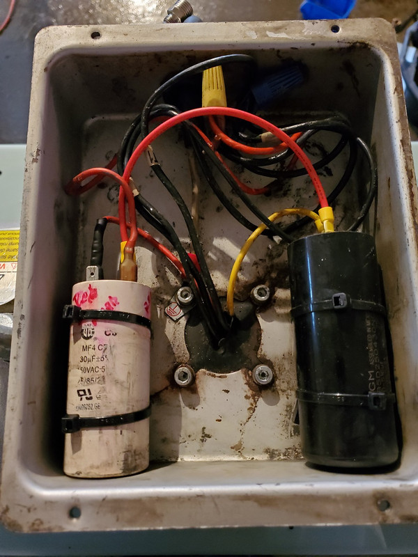
Is it worth changing the white cap since I have it apart? The black one has been replaced and has a date code of 2019. I'm pretty sure the white one is original. The motor ran fine when I bought it but to get at it later means taking off the cover panels.
 

DeeKay

Well-known member
Joined
Nov 25, 2020
Messages
448
Location
Colorado
Just a note on that fan, a lot of those stamped aluminum blades are only rated for 1550rpm...which might be why the original one was starting to come apart too.
 
OP
5

51dueller

Well-known member
Joined
Feb 22, 2021
Messages
221
Location
Saskatchewan
It would be nice to find a steel fan for the higher rpms. It was hard enough to find a blade that would fit let alone someone that could order it. Being that a new fan blade is $11 CDN, I probably could keep a spare hanging on the wall.

I started cleaning the oil separator tank and found the bottom had a thick layer of burnt oil. It's the same as when I clean out the exhaust oil traps on locomotives at work.

21.jpg


Is it really that hard to change oil regularly? At least the metal is nice and shiny underneath. Tomorrow I'll see if a radiator shop can clean my cooler and tank. The last thing I want is any grit getting into the pump. The oil I drained out of the pump looked pretty clean. I'm not taking the pump apart as I know I'll never find any seals or gaskets.

Now I'm beginning to see why the guy I bought it from decided to stick with a "simpler" (his words) reciprocating piston pump. He picked it up from the original owner who had it about 10 years and did some wiring to get it working. Then he picked up a big 2 cycle cast iron DeVilbiss pump to rebuild and decided to go with that instead. I'm just the poor sap that bought it off him.:bounce:
 
OP
5

51dueller

Well-known member
Joined
Feb 22, 2021
Messages
221
Location
Saskatchewan
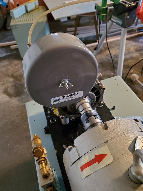
It now has an air filter again:

22.jpg

23.jpg


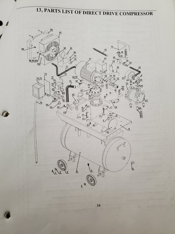
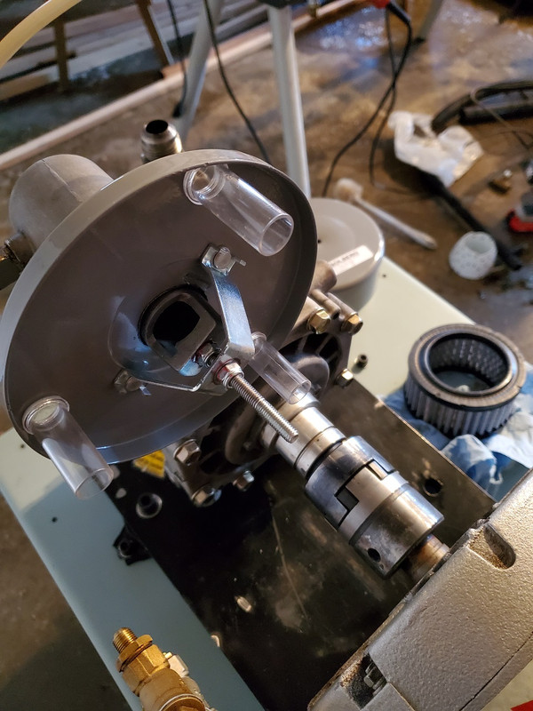
I removed the pipe fitting it came with and only had to open up the hole slightly to get it to fit. It's rated at 35 scfm which is twice what this compressor is supposed to do. It now looks like what the parts diagram shows for the air filter assembly.

Just waiting to hear back from the radiator shop when the cooler and tank are clean. The oil separator is supposed to show up tomorrow.
 

MacMcMacmac

Well-known member
Joined
Oct 21, 2014
Messages
1,591
Location
canada
Looking great. Make sure the siphon tube that goes down into the separator fully reaches the bottom. If it doesn't have an angled end you should probably give it one, since a flat end pressed against the bottom of the separator is almost like having it plugged up. Some companies put a 90 deg bend in the end and sucked in sideways.

It is common practice to pour oil down the inlet of a rebuilt screw compressor. It might not hurt to prime the scroll a bit so it starts compressing right away and has enough lube to protect it at startup. You don't know how long it sat unused.
 
To avoid these ads, REGISTER NOW!
OP
5

51dueller

Well-known member
Joined
Feb 22, 2021
Messages
221
Location
Saskatchewan
Got the oil cooler and oil separator tank back from the radiator shop. The oil cooler passed a pressure test and the tank's paint had seen better days but all the gunk inside it is gone. Gave the tank two coats of paint.

24.jpg

25.jpg


Here's the new filter vs the oil one. The new one is 15mm longer but the other dimensions are the same. I'm happy it even came with new gaskets.

26.jpg

27.jpg


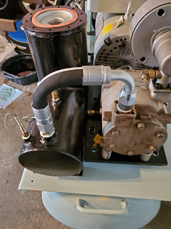
I didn't like the braided hose that they had made as it touched the top of the cover and it had a solid NPT fitting on the one size. I got a new hose made and now it matches the parts diagram again. It's a single braid 1250 psi hose so I shouldn't have any issues with it.

28.jpg

29.jpg


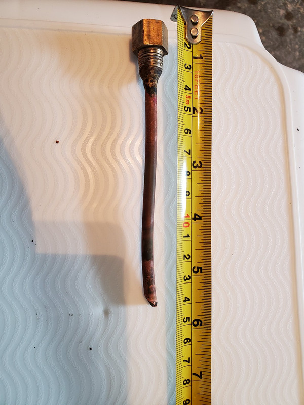
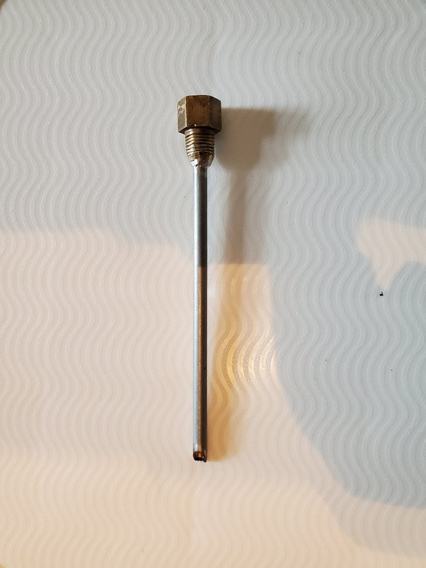
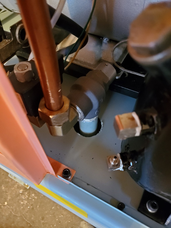
Since the filter is longer, I needed to remake the oil pickup tube. It was 1/4 copper line so I bought a foot of 1/4 brake line. It was braised into place so I cut it and started to drill it out. The drill bit pulled out what was left of the line. It sure has a small hole in the brass fitting and of course it was plugged. Ended up taking a single wire strand from a 14 gauge wire and running it through. The 1/4 brake line was snug and had to be tapped into place. I soldered it into place as I don't own an acetylene torch setup.

30.jpg


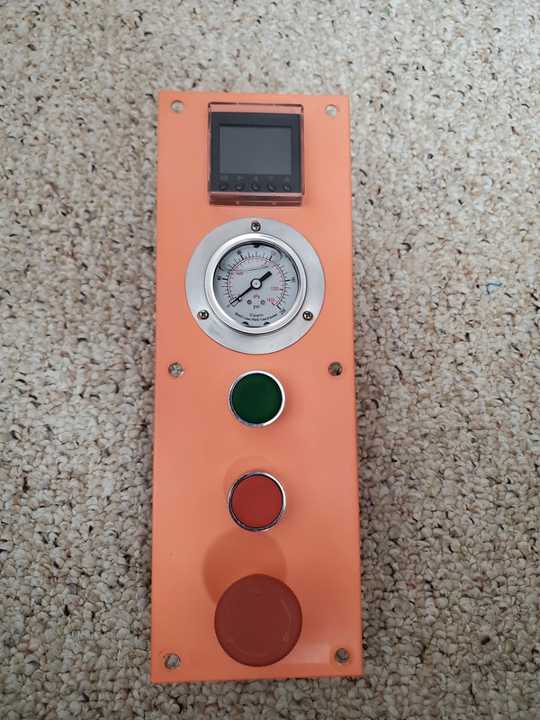
Got the center panel all clean and mounted plus other little odds and ends.

31.jpg


I was hoping to still fit the magnet starter under the cover but its too big. Looks like I'm going to have to make some brackets to put it on the side as I want to keep the whole unit mobile.

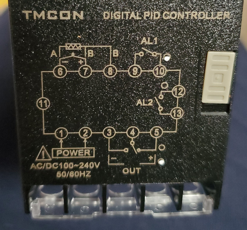
Still waiting for new nylon lines and start/stop buttons. The temperature controller is here.
 

MacMcMacmac

Well-known member
Joined
Oct 21, 2014
Messages
1,591
Location
canada
Nice work. I am worried about no staple in the separator gasket. The separator really needs to be grounded to the case.

The small hole in the siphon line is to limit the amount of air loss back to the inlet while providing a return path for the separated oil. Ideally it would be a stream of pressurized oil and no air loss but that is impossible to achieve really. If this small hole plugs you will gradually pump all of your oil into the tank and air system. This may have been the reason it was ditched by the first owner and the reason the separator tank was full of sludgy oil.

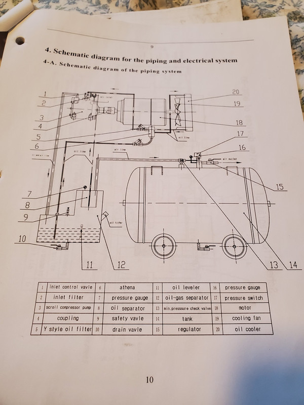
I am curious if in the parts list there is a listing for a minimum pressure valve? There is usually a spring loaded valve on the discharge of a screw or vane style compressor to ensure sufficient air pressure is built up inside the machine before it sends air down the line. Air pressure = oil pressure on machines not fitted with a dedicated oil pump. Very few are nowadays. It was more common on older screws and portable compressors that had to idle down.
 
Last edited:
OP
5

51dueller

Well-known member
Joined
Feb 22, 2021
Messages
221
Location
Saskatchewan
Well I feel stupid that I removed the staples. Never thought the filter would build an electrical charge. I took it apart and put them back in the gaskets. I know for sure the original gaskets I had to chisel off didn't have any staples.

Isn't the pickup tube in the top flange only for removing any oil that got through the separator and is pooling in the bottom? The tank has a feed line on the side, well below the oil line which goes to a pressure bypass block before going to the oil cooler and back to the bypass block which then feeds the scroll pump directly. The block looks exactly like what Ford uses on their transmission cooler lines. If the fluid is too cold to flow or the cooler is blocked it bypasses back into the transmission.

32.jpg


33.jpg

34.jpg


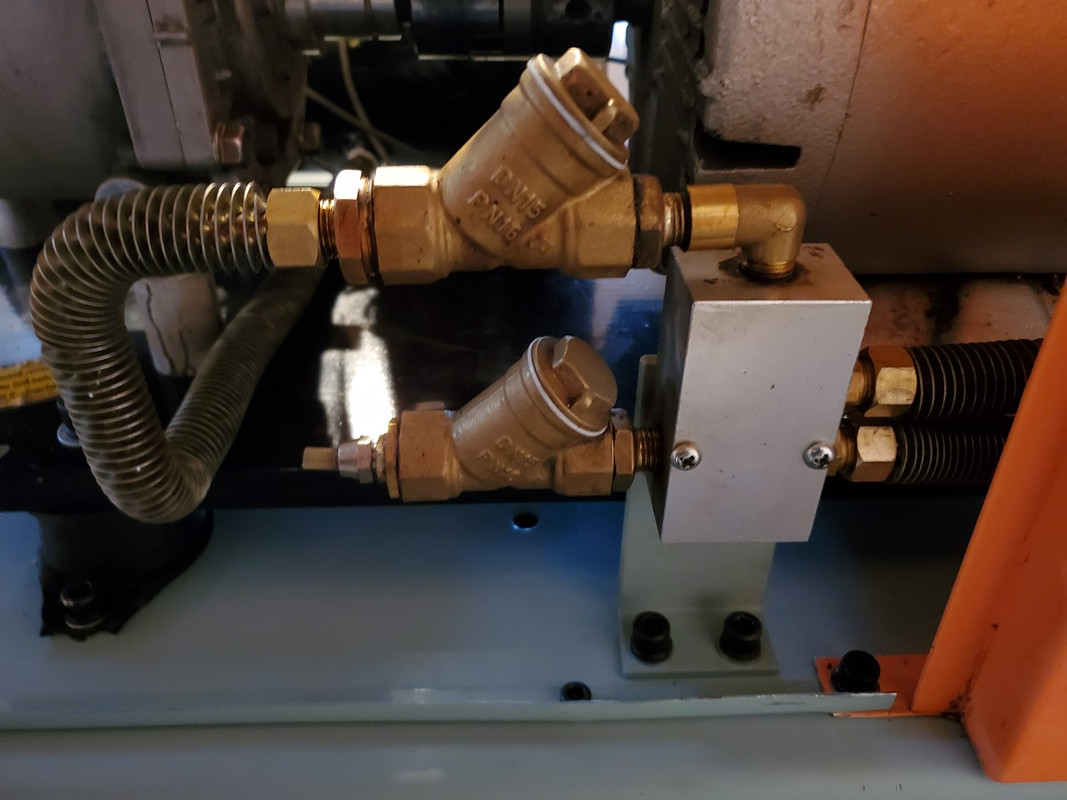
There is a spring loaded valve in the inlet of the tank with an electric unloader before it that opens when the tank has reached max pressure. The diagram even calls it a minimum pressure check valve. I just noticed it calls the Y pipe fittings an oil filter. I think I might have to open them up and check if they have a screen in there.
 

MacMcMacmac

Well-known member
Joined
Oct 21, 2014
Messages
1,591
Location
canada
Ok, so there is a minimum pressure valve, good. The two Y strainers should have a fine screen in them to filter out larger particles. By the look of the oil debris, I would not be surprised if they were full of "coffee grounds" or worse. Y strainers are very common in steam and gas lines to catch coarse ****, but they aren't the last word in filtration by any means.

The block they mount to is indeed a temperature control valve. Oil will be directed back to the scroll when cold, and through the cooler when hot. Usually this is nothing more complex than a simple wax thermostat inside the case. There may be a replaceable module inside if it fails.

I'm curious about the control setup. If it blows down the line at the check valve I would expect it to also close the inlet valve somehow to limit the amount of air being produced once up to pressure.

BTW, assuming it runs ok when you're finished, I hereby award you with the coveted Garage Journal

YOU ****! for obtaining such a unique machine for very small money!
 
Last edited:
OP
5

51dueller

Well-known member
Joined
Feb 22, 2021
Messages
221
Location
Saskatchewan
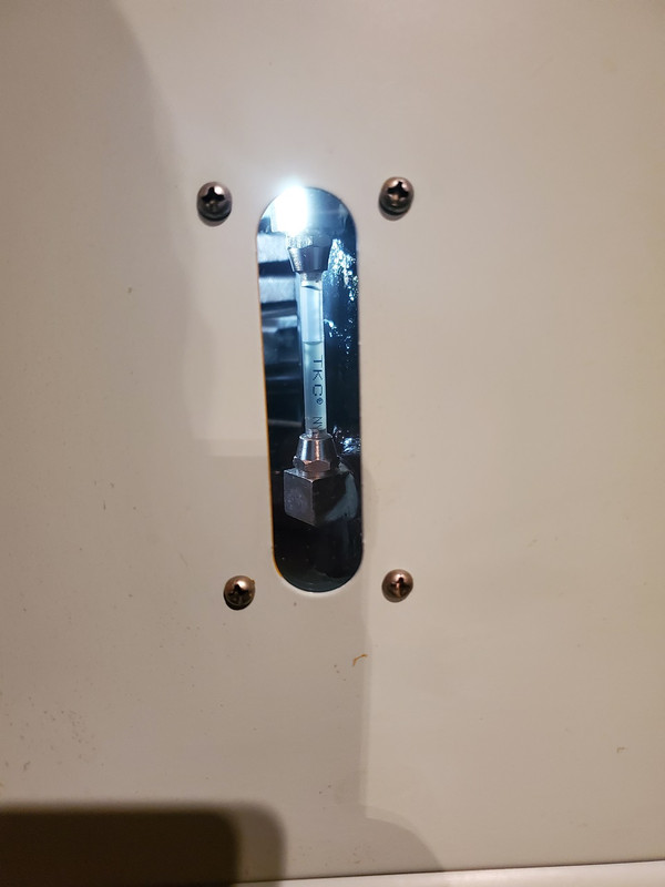
Not big progress but the yellow paint is finally gone! Scrubbing the louvers took forever. I need to make a new sight glass window as the original is too scratched to see through.

35.jpg


The oil strainers were pretty gummed up. I got them soaking to get them clean. I tried to find new ones but don't seem available without buying the whole fitting and they look much coarser than the ones I have.

The nylon tubing should be here on Friday so I'll be able to get the reservoir full of oil and the pump hooked up again.
 

MacMcMacmac

Well-known member
Joined
Oct 21, 2014
Messages
1,591
Location
canada
I am wondering how much sludge is built up inside the compressor itself. The valve plates might be in a bit of a state.

Hard to know what oil was used in it. When I had a sludgy oil cooler at work a few years ago, I contacted Petro Canada and they recommended using diesel engine oil as a flush. ATF does an amazing job of keeping things clean but is not used as a compressor lube anymore since it is too foamy and better compressor specific oils are available now. It would be a cheap cleaning agent though. Run it good and long to get heat into the system and put the machine through its paces. You might get some carryover into the air system since it doesn't coalesce as well as compressor fluids but that is a temporary issue.

I'd really love to know who sold that machine initially.
 
OP
5

51dueller

Well-known member
Joined
Feb 22, 2021
Messages
221
Location
Saskatchewan
The nylon tubing came early so I got it all installed. The oil strainers came out clean after soaking in oven cleaner overnight. I turned around the one Y strainer so the flow direction is the correct way.

36.jpg


Made a new slight glass window out of acrylic sheet.

37.jpg


I currently have 5 litres of oil in the tank. I know it will need more once it fills the oil cooler. Much easier to add more than remove some later.

While I'm not against getting the pump clean. I'm not sure how to really get out all the engine oil out of the system. The only drain is in the tank and it is only 1" from the tank mounting plate. I don't imagine it would be best to mix engine oil and compressor oil afterwords.

As far as who made it. I searched the CSA number and found the ZHE JIANG JINLONG ELECTRICAL MACHINERY STOCK CO., LTD was listed. Looking at their website, they only make electrical motors which they most likely supplied for it. CSA gave them approval in 2012 so I think its newer than I thought.

Being in Saskatchewan, we don't have the population for finding deals on big quality industrial equipment that seems prevalent on Garage Journal. Just lots of consumer grade junk that people want too much for.

I imagine it most likely purchased in Alberta and brought back. I don't think it would have been imported directly from China for someone's personal use as then I wouldn't have an english manual and the motor would most likely be 50 hz.

I wonder if someone tried to do a start up business and it didn't work out. Seems odd that nothing comes up in a search other than this thread. But if it is a 2012, they beat Eastwood by 5 years for having a entry level grade scroll air compressor.
 
OP
5

51dueller

Well-known member
Joined
Feb 22, 2021
Messages
221
Location
Saskatchewan
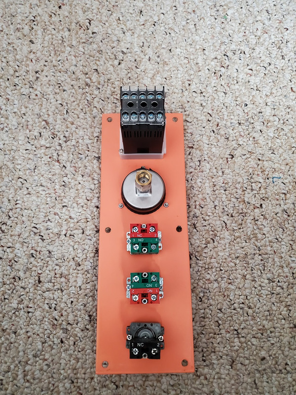
Finally got my electrical switches and new pressure gauge since I scratched it trying to clean it. Of course the new gauge is slightly smaller than the original so I bridged the gap with electrical tape. The panel was like made for these switches as they had little dimples for the screws to go into.

38.jpg

39.jpg


Now for the electrical wiring:

40.jpg


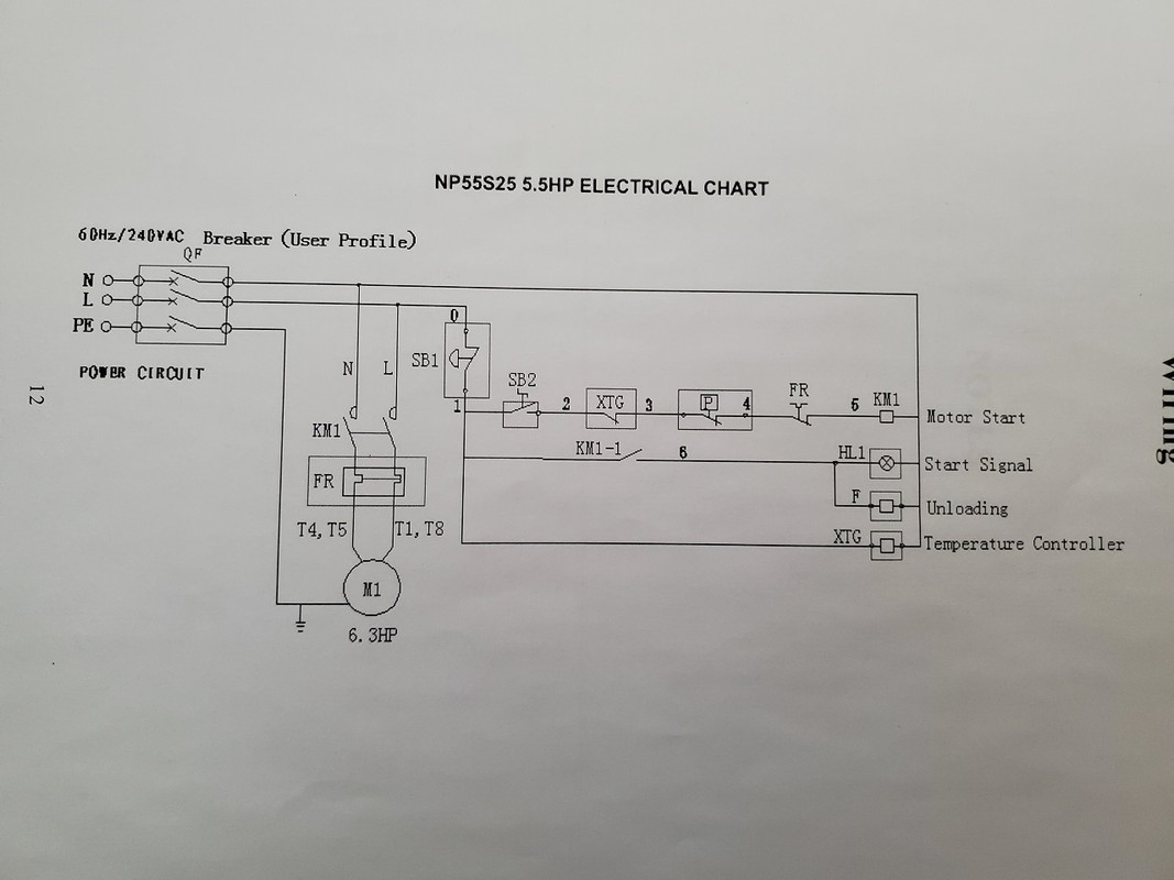
This is what the owners manual has. From what I understand:
SB1 - Emergency stop switch
P - Pressure switch
Green button should be normally open
Red button should be normally closed

I'm used to automotive diagrams and they are normally laid out nicer than this. The Square D magnet starter has 1L1 and 3L2 terminals. Am I also missing any other electrical items that the diagram shows? Any help is much appreciated as it would be nice to actually fire it up after 2 months.
 

DeeKay

Well-known member
Joined
Nov 25, 2020
Messages
448
Location
Colorado
Ladder diagrams take some getting used to if you normally look at automotive stuff but once you're used to them they're waaaaaay better. Looks like they used IEC symbols for this one which makes sense for where it was made.

That schematic is showing SB2 as a two position maintained selector switch.
If you want to use the momentary start/stop push buttons you would have to use an auxiliary N.O. contact off of your starter to parallel the N.O. start button. and reconfigure some other stuff. If that's what you're after you need to make sure you have an extra aux contact on the starter, this is what's called a 3 wire start/stop circuit. If you do want to go this route I can help you with a new schematic.

This drawing is a little goofy, they're showing a neutral but it's actually using 240V control power, not 120.
The way they set this up from the factory is kind of odd/stupid IMO, they're cycling the motor every time the compressor unloads....normal for a recip but seems weird for something like this....though I've never worked on a compressor smaller than 40HP thats not a recip so maybe all of the little ones are similar.

post a pic or part number of the starter you bought and make sure that temp switch is 240v input.

SB1: E-stop pushbutton, N.C. maintained
SB2: Start/Stop, 2 position maintained selector switch
XTG: High temp shut down, N.C. contact off of the temperature switch.
P: Pressure Switch, normally closed, opens on high pressure
FR: looks like the starter overloads, it's just drawn weird
KM1: motor starter
KM1-1: motor starter aux contact, N.O.
HL1: pilot light,
F: unload solenoid, most likely N.O.
XTG: temp controller power
 
Last edited:
OP
5

51dueller

Well-known member
Joined
Feb 22, 2021
Messages
221
Location
Saskatchewan
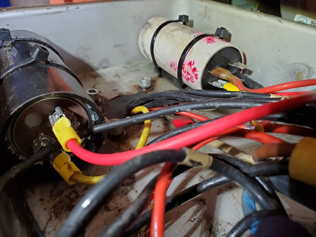
If you could provide a diagram it would be most helpful. I didn't change any of the capacitors. The start capacitor is a NGM 250Vac 430-516µF 61B5D250430NCAC. If I need something different in order to use my buttons I'll get it.

41.jpg


The run capacitor wires are as follows:
Heat shrinked wire - out of the motor
yellow crimp - start capacitor
rubber insulated wire - to L1 wire out of motor and main power feed

Here's the temperature controller diagram:

42.jpg


I'm not worried about the high temperature shutdown right now as I have to figure out how to even program it. It's the SSR version so it has a 5v output to trigger a relay. I can always add the relay at a later date if I notice it running hot.
 

DeeKay

Well-known member
Joined
Nov 25, 2020
Messages
448
Location
Colorado
I was talking about the motor starter, or magnetic starter as everyone calls them on this forum. Not the start cap.

In order to use a three wire start/stop circuit(using the momentary push buttons you have) we have to make sure we can completely unload the compressor while keeping the motor running. Does that unloader solenoid valve close the inlet or does it just dump air from the sump? I can't tell from the pics. If we can't unload the compressor completely while running then you're going to be stuck using a two position selector switch like the factory schematic shows.

On screws that can unload while still keeping the motor running there are two valves, one that dumps air from the sump and one that closes the inlet at the same time: the motor stays running, but the compressor isn't making any air.
 
OP
5

51dueller

Well-known member
Joined
Feb 22, 2021
Messages
221
Location
Saskatchewan
The Square D magnet starter is a 8911DPSG42V09.

The unloader just releases the pressure in the oil separator tank. It's an electric magnetic coil that moves the valve. The coil part just slides over the valve assembly and held in place with a nut. I can switch to different pressure switch with a mechanical unloader valve if that would work better. I have all the flaring/bending tools so it isn't a problem.
 

MacMcMacmac

Well-known member
Joined
Oct 21, 2014
Messages
1,591
Location
canada
Stick with the solenoid. You want to vent as much air as quickly as possible to blow down the whole tank. Is there any inlet control valve on this scroll, or is it just an open intake with a filter on it? I see no provision for controlling an intake valve, which would make a constant run mode a bit more challenging to implement.
 
OP
5

51dueller

Well-known member
Joined
Feb 22, 2021
Messages
221
Location
Saskatchewan
Got the magnet starter mounted and everything wired except the control side. I had to change the wiring to the motor since the original was now too short. The white wire is not connected to anything as I only had some 4 wire cord and to buy new 3 wire cord costs twice as much as the 4 wire stuff. The electrical cord is a welder extension cord I cut the end off. I like having molded plugs as they look nicer and it cost the same as just buying cord and separate plug.

43.jpg

44.jpg


There is no valve on the inlet on the pump. I don't need anything fancy like a rotary where it idles down. The wiring diagram is for the next size up motor than mine so maybe there is a few differences.

How mine was wired when I got it:

power from starter to pressure switch to emergency switch to on/off power switch and back to to starter

The unloader was wired to these two terminals noted by the green arrows:

45.jpg


How it ran when I bought it was once it reached max pressure, the pressure switch shut the motor off and the unloader activated.

I don't think the motor needs to run with the unloader activated. In your vehicle your a/c compressor doesn't get its pressure relieved once you turn the vehicle off.
 
Last edited:

RTM

Well-known member
Joined
May 13, 2019
Messages
13,228
Location
SF Bay Area
On the Schneider relay, A1 and A2 are usually the coil, the NO pair are your normally open switch, the coil keeps it closed when energized.

If, as you said the unloadeR SV was wired to that pair, I’m drawing a blank on how. Your F on the wiring diagram above IS in theory the coil of a solenoid, not a relay, as the don’t show contacts, I.e they don’t show wiring to a relay. I c/would imagine that someone changed things post factory, and the SV could be grounded through the relay, but that’s getting odd IMO.
 

MacMcMacmac

Well-known member
Joined
Oct 21, 2014
Messages
1,591
Location
canada
Correct, the motor does not keep running in a stop start configuration. You also don't need an inlet valve since it is pumping at 100% all the time it runs. Whatever discharge valve resides inside the case acts as an oil stop valve to prevent oil backflowing to the scroll when it shuts down. The unloader dumps pressure from the tank before the minimum pressure/check valve so the whole unit can start without pressure at the next cycle. This also stops pressurized oil from flooding into the scroll from the oil injection line and stops oil flow from the scavenge line inside the separator. If there was no blowdown, pressure in the tank would keep feeding oil into the scroll and flood it, maybe even causing oil to pour out back through the air filter. That's why you need to dump the air asap.

I am a little surprised that this cannot be used as a constant run compressor since this is one of the major benefits of using an oil flooded compression element. The active oil cooling allows for a 100% duty cycle. I suppose the quieter operation is the main benefit of this machine, as well as a lack of vibration. It would not be a huge job to modify it to run constantly.

One thing bothers me though. It looks like you are in a residential garage. Do you have enough electrical service to run a 5hp motor? I am also questioning running it off of a plug. Electricians would be the best people to guide you on that.
 

DeeKay

Well-known member
Joined
Nov 25, 2020
Messages
448
Location
Colorado
Got the magnet starter mounted and everything wired except the control side. I had to change the wiring to the motor since the original was now too short. The white wire is not connected to anything as I only had some 4 wire cord and to buy new 3 wire cord costs twice as much as the 4 wire stuff. The electrical cord is a welder extension cord I cut the end off. I like having molded plugs as they look nicer and it cost the same as just buying cord and separate plug.

There is no valve on the inlet on the pump. I don't need anything fancy like a rotary where it idles down. The wiring diagram is for the next size up motor than mine so maybe there is a few differences.

How mine was wired when I got it:

power from starter to pressure switch to emergency switch to on/off power switch and back to to starter

The unloader was wired to these two terminals noted by the green arrows:

How it ran when I bought it was once it reached max pressure, the pressure switch shut the motor off and the unloader activated.

I don't think the motor needs to run with the unloader activated. In your vehicle your a/c compressor doesn't get its pressure relieved once you turn the vehicle off.

Without an inlet valve in addition to the unload you're going to be stuck with going back to a two position selector switch and having the motor shut off every time you make setpoint.
There's no way to use the two momentary pushbuttons you have unless you want to hit the start button after every time it makes pressure setpoint.
As for how it was wired before, who knows.

I don't see any aux contacts on your new starter so you'll either have to parallel the coil terminals with a control relay or go back to the Schneider since it has aux contacts
 
OP
5

51dueller

Well-known member
Joined
Feb 22, 2021
Messages
221
Location
Saskatchewan
As for running it off a plug, a welder plug is rated up to 50 amps at 250v. I have a 40 amp breaker on my circuit. I'm not sure how much it is a true 5.5hp as the 10 gauge wire I used to wire the motor is bigger than it originally had. The original sticker said it was 25 amps.

I used the Schneider relay without the overload to trigger the magnet starter and run the switches. I'm using the other side of pressure switch to trigger the unloader as it opens when not powered.

I finally got the temperature display to switch to pt100 so displays the right temperature. I've got it up to 90'C. The videos below were made before I fixed it.
46.jpg


How long it takes to fill from empty:

How well it keeps up to a 1/4 die grinder:

Well there we go, its back into operational shape. I think the new fan moves more air than the old one. I need to replace some of the foam on the cover panels which might make it a bit quieter.
 

MacMcMacmac

Well-known member
Joined
Oct 21, 2014
Messages
1,591
Location
canada
Nice work.

However...

According to my pump up calculator, at 41 gallons tank capacity, from 0 to 135psi in 383 seconds (6:23) you are making about 7.8cfm. That's about 2hp worth of air.

There is a lot of performance missing somewhere. It would be nice to have a schematic of the pump's internal build to investigate.
 
Last edited:
To avoid these ads, REGISTER NOW!
Top Bottom