To avoid these ads, REGISTER NOW!

Hood Cowl Project

yaidunno

Well-known member
Joined
Feb 10, 2011
Messages
1,336
Location
WI
Hi all,

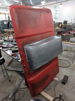
I’ve decided to take a break from polishing tools and put them to use. This will be my first endeavor in shaping body panels from scratch, so please bear with me here. I happily accept any and all criticism and advice!

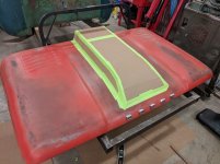
The project at hand is building and installing a hood cowl on a 61-65 Dodge D series truck. This hood presents some challenges in the body lines, but I believe I will be able to overcome them. The first step was to make a cardboard template of what I intended to build. My initial thoughts were confirmed: it was obvious that flat panels and square edges were not going to work on this large sweeping hood.

attachment.php


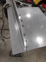
I determined that the cowl will be built from 3 main sections consisting of the two sides, and the top. My intent is to build this to the best of my abilities, so a practice run to test my theories and tooling is what will be covered in this first post. The sides will blend into the hood with a ½” radius, and the same radius will be used to transition into the new top. Step one was to build a tool from 1” bar stock to allow the brake to give me the desired bend radius. Flats were cut in the bar stock, and ½” tabs welded on.

attachment.php


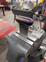
A small T-dolly was made to roll over on the top edge. I will be getting a rawhide hammer to do this on the final pieces. The faces on my urethane hammers are pretty beat up. It should be noted that after the sides get the first bend in the brake, I will need to stretch the vertical side to match the existing hood profile. I currently only have access to the standard issue shrinker/stretcher set, and fear that I will not be able to reach far enough in with them. In any case, I got ahead of myself and forgot to grab a photo after the top edge was rolled.

attachment.php


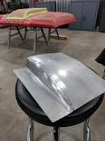
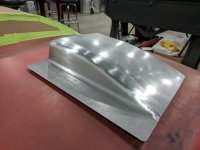
After I was satisfied with the side, I began to form and roll the top in the English Wheel. Once the shape closely matched the contour of the side, a line was scribed to cut along. It took a good deal of filing and belt sanding to get the gap just right, but it is necessary for a proper distortion free weld. Here the part has been tacked up.

attachment.php


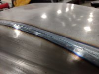
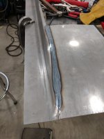
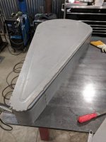
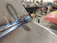
Happy with the tacked piece, it was time to run a pass. The machine was set at 60 amps and 3 PPS. As you can see, it’s been some time since I’ve run a bead on light material, but I was able to get it together. A wise person would run some test blanks, but I just went with it. I’m thinking that 55 amps will be better suited for 18 gauge material. The final pieces will be made from 19 gauge, and I will certainly be spending some torch time with samples before striking an arc on real deal.

attachment.php


I was able to adjust along the way with the pedal and get the heat under control. Ideally, the welder will be set at the correct amperage and floored which will allow me to concentrate on running the torch.

attachment.php


It was getting late at this point, so tonight I will work on bumping things around and metal finishing the weld.

attachment.php


Thanks for reading. More updates to follow.
 

Attachments

  • IMG_20171116_194031.jpg
    IMG_20171116_194031.jpg
    110.7 KB · Views: 1,108
  • IMG_20171127_221059.jpg
    IMG_20171127_221059.jpg
    66.3 KB · Views: 1,109
  • IMG_20171127_215920.jpg
    IMG_20171127_215920.jpg
    84.2 KB · Views: 1,101
  • IMG_20171127_215904.jpg
    IMG_20171127_215904.jpg
    59.9 KB · Views: 1,097
  • IMG_20171127_215432.jpg
    IMG_20171127_215432.jpg
    50.9 KB · Views: 1,109
  • IMG_20171127_202806.jpg
    IMG_20171127_202806.jpg
    77.3 KB · Views: 1,126
  • IMG_20171127_202833.jpg
    IMG_20171127_202833.jpg
    124.3 KB · Views: 1,115
To avoid these ads, REGISTER NOW!

larry_g

Well-known member
Joined
Apr 28, 2007
Messages
16,922
Location
oregon
The first thought that crossed my mind looking at your project was; To bad he doesn't have a second hood to cut up. Take 6-8" off each side of the hood and weld them together so the curves and rounding of the scoop would be the same as the hood sides. Could even have the louvered looking section near the window end of the scoop.

Anyway what your fabricating looks great. Workmanship like I'd expect to see on one of your projects, nothing less than great.

lg
no neat sig line
 
OP
Y

yaidunno

Well-known member
Joined
Feb 10, 2011
Messages
1,336
Location
WI
Nice job! Good write up! I will be doing the same thing for my Astro project, eventually.
Mark

Thanks Mark!

Looks good, a keeper in my opinion. I love your manual sheet metal bender.

The brake certainly comes in handy. Thanks for checking things out!

The first thought that crossed my mind looking at your project was; To bad he doesn't have a second hood to cut up. Take 6-8" off each side of the hood and weld them together so the curves and rounding of the scoop would be the same as the hood sides. Could even have the louvered looking section near the window end of the scoop.

Anyway what your fabricating looks great. Workmanship like I'd expect to see on one of your projects, nothing less than great.

lg
no neat sig line

Larry, initially the plan was to do something along the lines of what you mention, as far as finished product. These hoods are rather hard to come by though, so it would have been hand formed, and quite cost prohibitive. As such, I'll need to get the cowl made and approved by the customer before making any cuts in the hood.

Thanks for the feedback!
 

Stuart in MN

Well-known member
Joined
Sep 8, 2005
Messages
23,356
Location
Minneapolis
What's going under the hood that's going to require that big cowl? Something with a tunnel ram, or maybe a supercharger? :)
 
OP
Y

yaidunno

Well-known member
Joined
Feb 10, 2011
Messages
1,336
Location
WI
What's going under the hood that's going to require that big cowl? Something with a tunnel ram, or maybe a supercharger? :)

500 C.I. Mopar with a single plane manifold that will be putting out about 700 hp.
 
OP
Y

yaidunno

Well-known member
Joined
Feb 10, 2011
Messages
1,336
Location
WI
yaidunno, nice work and thank you for the detailed explanation..:thumbup::thumbup:

Thanks much 1/2 cup!

I found some time last night to get the weld and radius bumped around. Its close, but not 100%. I will be making a set of radius forming dies for the bead roller to allow me to form the upper radius, as there just isn't enough consistency forming it over the T dolly. Along with a more suitable weld temperature, this should help alleviate almost all post weld finish work.

The steel should be in by the end of the week, so hopefully I can make some progress on the cowl this weekend.

attachment.php


attachment.php
 

Attachments

  • IMG_20171129_214024.jpg
    IMG_20171129_214024.jpg
    60.2 KB · Views: 814
  • IMG_20171129_214127.jpg
    IMG_20171129_214127.jpg
    78.4 KB · Views: 816

larry_g

Well-known member
Joined
Apr 28, 2007
Messages
16,922
Location
oregon
images


One of the details that I've always thought was good looking was the extended top of the scoop giving a bit of a 'swoop' to the opening, as in the picture above, instead of a squared off opening.

lg
no neat sig line
 
OP
Y

yaidunno

Well-known member
Joined
Feb 10, 2011
Messages
1,336
Location
WI
images


One of the details that I've always thought was good looking was the extended top of the scoop giving a bit of a 'swoop' to the opening, as in the picture above, instead of a squared off opening.

lg
no neat sig line

Definitely. I will try to match the angle with the windshield. The down side is that it can limit the hood opening, which on this truck goes past 90 degrees IIRC.
 

rsanter

Well-known member
Joined
Dec 22, 2007
Messages
18,547
Location
visalia ca
Thanks much 1/2 cup!

I found some time last night to get the weld and radius bumped around. Its close, but not 100%. I will be making a set of radius forming dies for the bead roller to allow me to form the upper radius, as there just isn't enough consistency forming it over the T dolly. Along with a more suitable weld temperature, this should help alleviate almost all post weld finish work.

The steel should be in by the end of the week, so hopefully I can make some progress on the cowl this weekend.

attachment.php


attachment.php


Nice work and good writeup
I was going to suggest that you try forming the upper and lower radius on the bead roller. I think it will be easier

Also, it seems you have an English wheel.
Do some research as some of the older English wheels had the option of a crank feed on them. These can be used so the English wheel acts like a really big bead roller.
All you have to do is make the upper and lower to form the shape you want and then one person cranks while the other guides the metal

Bob
 

zmotorsports

ALLIANCE MEMBER
Joined
Oct 20, 2009
Messages
21,600
Location
Northern Utah
Great job on the cowl. Turned out awesome.

Can I ask what brand/model of finger brake you have? Also what is the brake's material capacity?

I have been waffling on a brake for a while and thinking of building one vs. purchasing. Much of it is trying to determine just how much I would use it as I don't do a ton of sheet metal work any longer.

Thanks.
 

astroracer

Well-known member
Joined
Jun 22, 2005
Messages
3,001
Location
Mid_Michigan
Great job on the cowl. Turned out awesome.

Can I ask what brand/model of finger brake you have? Also what is the brake's material capacity?

I have been waffling on a brake for a while and thinking of building one vs. purchasing. Much of it is trying to determine just how much I would use it as I don't do a ton of sheet metal work any longer.

Thanks.

Just jumping in here...
Check out Swag Offroad. They make some excellent benders that go in a hydraulic press. I got one of their early 20" models with a single bar. It will do 5/8th's steel in a 3" width.
They have an upgraded finger brake and an additional kit to put gooseneck dies in the finger brake.
http://www.swagoffroad.com/20-TON-Finger-Brake-Heavy-Duty-DIY-Builder-Kit_p_86.html
Well worth looking at, you will not build one for the price they are asking.
Mark
 

zmotorsports

ALLIANCE MEMBER
Joined
Oct 20, 2009
Messages
21,600
Location
Northern Utah
Just jumping in here...
Check out Swag Offroad. They make some excellent benders that go in a hydraulic press. I got one of their early 20" models with a single bar. It will do 5/8th's steel in a 3" width.
They have an upgraded finger brake and an additional kit to put gooseneck dies in the finger brake.
http://www.swagoffroad.com/20-TON-Finger-Brake-Heavy-Duty-DIY-Builder-Kit_p_86.html
Well worth looking at, you will not build one for the price they are asking.
Mark

Thanks. I already have the SWAG HD finger brake and although it is a well thought out and priced product it has its limitations as well. Still thinking about fabricating a larger pan/finger brake but having a hard time justifying when I don't do a ton of sheet metal work any more. Most of the fabricating I have been doing is on larger thickness material.

Thanks for the reply though.
 
OP
Y

yaidunno

Well-known member
Joined
Feb 10, 2011
Messages
1,336
Location
WI
Nice work and good writeup
I was going to suggest that you try forming the upper and lower radius on the bead roller. I think it will be easier

Also, it seems you have an English wheel.
Do some research as some of the older English wheels had the option of a crank feed on them. These can be used so the English wheel acts like a really big bead roller.
All you have to do is make the upper and lower to form the shape you want and then one person cranks while the other guides the metal

Bob

Hi Bob, I appreciate the feedback! As can be seen in some of the photos, forming that upper radius left a good amount of lumps and irregularities. Running it through some rolls should really simplify this.

Unfortunately, my wheel is not really suitable for use as a large roller. It would take a good deal of modification, along with specific dies to make work.

Great job on the cowl. Turned out awesome.

Can I ask what brand/model of finger brake you have? Also what is the brake's material capacity?

I have been waffling on a brake for a while and thinking of building one vs. purchasing. Much of it is trying to determine just how much I would use it as I don't do a ton of sheet metal work any longer.

Thanks.

The brake I have is a W31 by Dreis and Krump. Its capacity is 14 gauge material at 48" in width. At roughly 1300 lbs, it is quite a robust little brake that can handle .090 aluminum sheets with ease. Their current offering is a model BPU 412-6. It's rated for 12 gauge steel and comes in at just over 2000 lbs.

This one had seen some abuse in its life, but the frame was still straight and true. The fingers and holders, not so much. I made new finger "tips", if you will, from 4140 HT, and the holders from 1018 CRS. It was time consuming, but after a bit of adjustment, the brake is functioning like new.
 
OP
Y

yaidunno

Well-known member
Joined
Feb 10, 2011
Messages
1,336
Location
WI
Just a quick update on this project. I got a chance to spin up some round over dies for the bead roller this weekend. They work quite well. Of course, I neglected to take a photo of any of the sample pieces.

attachment.php


A side project, but it gave me some time to dial in the TIG welder for 18 gauge material. 50 amps seems to do the trick with a minimal HAZ.

attachment.php


As I expected, the small shrinker and stretcher set did not have nearly enough reach to make the curve on the front of the hood. A 16 ga. *********** one will be ordered today.
 

Attachments

  • IMG_20171203_214148.jpg
    IMG_20171203_214148.jpg
    80.7 KB · Views: 606
  • IMG_20171203_141708.jpg
    IMG_20171203_141708.jpg
    62.4 KB · Views: 601
To avoid these ads, REGISTER NOW!
OP
Y

yaidunno

Well-known member
Joined
Feb 10, 2011
Messages
1,336
Location
WI
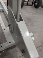
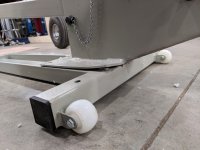
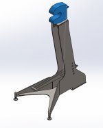
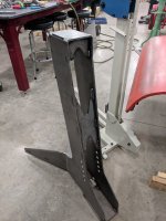
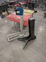
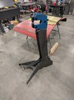
Last night I received my Chinese white and blue shrinker/stretcher. My expectations for this unit weren’t overly high, given my previous experiences with imported stuff, but I thought maybe things have improved over the years. They have not. This little guy was either tossed around at the factory, or had a rough ride in on the banana boat. I knew going into this that the stand wasn’t worth the cheap metal it’s made from, so a new one will be made in the following days. The finish goes from smooth and glossy to rough textured due to lack of paint, nice. Disclaimer: the stand design is loosely based on a design from an excellent fab shop in AZ.

attachment.php


Missing paint and rust are standard issue.

attachment.php


Bent flanges: check.

attachment.php


Despite the short comings, this copycat machine works fantastically well. It’s in a whole different league compared to the Lancaster style shrinker/stretcher units, and really moves some metal when you put some weight into the pedal. While it is a very effective tool, I think its priced a bit high given the lack of quality. Unfortunately an Erco or the like is about 5X out of my price range.

attachment.php


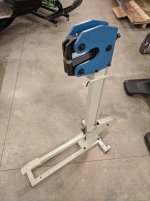
This is what it will sit on in a few days.

attachment.php


I got a chance to start on one of the sides last night as well, and I’m not 100% certain that this is the right approach. It is useable, and will clean up, but I almost wonder if cutting out the flat sheet to match the hood profile, then beading both top and bottom with the rolls would save me some effort in metal finishing it? One thing I think I need to do is manage my expectations. I’ve got this vision of a perfect metal finished and body filler free panel. The truth is, it’s not likely to happen on my first attempt at making something like this from scratch. One thing I do have going for me is that the 19 ga material is a breeze to work with.

More to follow soon.
 

Attachments

  • IMG_20171206_162246.jpg
    IMG_20171206_162246.jpg
    61.3 KB · Views: 501
  • IMG_20171206_162251.jpg
    IMG_20171206_162251.jpg
    121.1 KB · Views: 500
  • IMG_20171206_182854.jpg
    IMG_20171206_182854.jpg
    98.8 KB · Views: 497
  • IMG_20171206_215416.jpg
    IMG_20171206_215416.jpg
    125.5 KB · Views: 502
  • STAND.jpg
    STAND.jpg
    43.7 KB · Views: 499
OP
Y

yaidunno

Well-known member
Joined
Feb 10, 2011
Messages
1,336
Location
WI
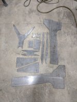
I got a start on the stand yesterday. It should be ready for use this weekend.

attachment.php


attachment.php


attachment.php


attachment.php
 

Attachments

  • IMG_20171207_203542.jpg
    IMG_20171207_203542.jpg
    92.1 KB · Views: 1,666
  • IMG_20171207_203534.jpg
    IMG_20171207_203534.jpg
    95.1 KB · Views: 1,675
  • IMG_20171207_200701.jpg
    IMG_20171207_200701.jpg
    114.2 KB · Views: 1,673
  • IMG_20171207_165113.jpg
    IMG_20171207_165113.jpg
    75.7 KB · Views: 1,668
OP
Y

yaidunno

Well-known member
Joined
Feb 10, 2011
Messages
1,336
Location
WI
Nice work

Thanks

Yaidunno,
You sure build neat stuff.
Thanks

Royce

Thank you Royce. Quite the compliment, considering the things that come out of your shop!

Wow great stand!...do you own a CNC plasma table (or have access to one?)

Thanks Matt. There is a shop down the road from me that I go through.

Here are a few shots of the details on the stand, and where I sit with the cowl. I spent a good deal of time on Saturday turning parts and welding them up for the stand. I'm really happy with how it turned out and its functionality.

attachment.php


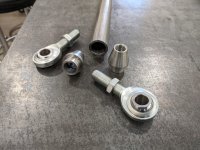
Linkage parts and rod ends. One LH and one RH for quick and easy adjustment.

attachment.php


Really wish I had a rotary head for welds like this.

attachment.php


Spun up a knurled hand knob for adjustment.

attachment.php


Spun up these little guys for the adjustment feet.

attachment.php


Here's the completed stand. There is a spring that is installed on the back end of the pedal. The pedal rides in oil lite bushings on a .75" pin that was turned.

attachment.php


I ended up making the sides by cutting them to shape, then rolling the edges. The shrinker stretcher was still used to tweak the part to final shape. Don't mind the braces.

attachment.php


And this is where I sit as of last night. I'll get it welded up tonight and finish off the back side as well.
 

Attachments

  • IMG_20171212_212344.jpg
    IMG_20171212_212344.jpg
    94.7 KB · Views: 318
  • IMG_20171210_210743.jpg
    IMG_20171210_210743.jpg
    105.4 KB · Views: 317
  • IMG_20171209_160137.jpg
    IMG_20171209_160137.jpg
    73.5 KB · Views: 1,533
  • IMG_20171209_155938.jpg
    IMG_20171209_155938.jpg
    96.4 KB · Views: 1,534
  • IMG_20171209_155904.jpg
    IMG_20171209_155904.jpg
    47.9 KB · Views: 1,519
  • IMG_20171209_112922.jpg
    IMG_20171209_112922.jpg
    53.1 KB · Views: 1,523
  • IMG_20171209_112305.jpg
    IMG_20171209_112305.jpg
    121.4 KB · Views: 1,525

zmotorsports

ALLIANCE MEMBER
Joined
Oct 20, 2009
Messages
21,600
Location
Northern Utah
Beautiful work.

One of the best purchases I have made in years was my M-K Products Model 3 aircraft positioner. I looked for a couple of years before finding a nice clean one. They are sure nice to have for welding links, etc.

If you don't mind me asking, what radius turning tool/attachment do you have and use? Those radii for the adjusting feet turned out great.

Love following along.
 
OP
Y

yaidunno

Well-known member
Joined
Feb 10, 2011
Messages
1,336
Location
WI
Beautiful work. Nice to see some of that vintage equipment get put to use.

Thanks Robert! This sheet metal game is a whole different animal, but its fun and a good challenge.

Great work!!

Thanks G1K

Beautiful work.

One of the best purchases I have made in years was my M-K Products Model 3 aircraft positioner. I looked for a couple of years before finding a nice clean one. They are sure nice to have for welding links, etc.

If you don't mind me asking, what radius turning tool/attachment do you have and use? Those radii for the adjusting feet turned out great.

Love following along.

I've been doing a bit of research on different positioners, and have set aside a nice little 6" chuck for the day one arrives. Thanks for the lead on the MK company, have not heard of them.

The radii are all done by hand. I start by roughing out the basic shape, controlling both hand wheels and using my best judgment. After that, I clean it up with a file, and then a light sanding. I'd certainly like one of those fancy radii cutting tools though!

Thanks for checking things out.
 
OP
Y

yaidunno

Well-known member
Joined
Feb 10, 2011
Messages
1,336
Location
WI
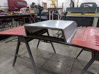
A quick update on what might be the most time consuming hood cowl project ever. I got both sides welded on and roughed out. the work that it would take to bump and metal finish these parts is not something the customer is willing to pay for, so a skim coat of mud will have to hide the ugly. I've heard (and it sounds quite reasonable) that it takes about an hour per linear foot of weld to fully straighten and finish. There's about 14' worth on this project.

Last night I took the plunge and cut a gaping hole in a perfectly good hood. It was a bit intimidating, but its just metal, so away I went. Taking the time to make sure the cowl fit the hood properly before hand really paid off when it came time to taking this thing together. Hopefully it will be finished up by tomorrow.

attachment.php


attachment.php
 

Attachments

  • IMG_20171217_220347.jpg
    IMG_20171217_220347.jpg
    112 KB · Views: 203
  • IMG_20171217_220355.jpg
    IMG_20171217_220355.jpg
    61.7 KB · Views: 201
OP
Y

yaidunno

Well-known member
Joined
Feb 10, 2011
Messages
1,336
Location
WI
Had almost as much fun looking at the clean shop as I did the cool project!

Jeeze, I've been waiting to get this project finished up so I can finally clean! Its been a disaster the past few weeks. Tripping over stuff and not being able to find stuff gets irritating.

But on that note, the hood is done!

attachment.php


Here its in a more friendly position to weld.

attachment.php


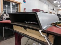
These little end pieces finish it off nicely.

attachment.php


Back end all done.

attachment.php


All set, and fresh out of gas for the TIG.

attachment.php


Here's a quick teaser for the next stand being built. It's a Christmas gift for my father, who is lacking a proper stand for his Lancaster's. I will be documenting this in the shop tools thread.

Thanks for looking!
 

Attachments

  • IMG_20171218_224711.jpg
    IMG_20171218_224711.jpg
    79.7 KB · Views: 164
  • IMG_20171218_224622.jpg
    IMG_20171218_224622.jpg
    101.2 KB · Views: 164
  • IMG_20171218_205144.jpg
    IMG_20171218_205144.jpg
    87.2 KB · Views: 163
  • IMG_20171218_190555.jpg
    IMG_20171218_190555.jpg
    63.3 KB · Views: 165
  • IMG_20171218_224011.jpg
    IMG_20171218_224011.jpg
    76.2 KB · Views: 164
OP
Y

yaidunno

Well-known member
Joined
Feb 10, 2011
Messages
1,336
Location
WI
Looking good! What's going to fill up that cowl?

Sleeper no more :lol:

Thanks Robert! It will be covering a big block Mopar. Between the hood and the nosie, I don't think anybody will mistake it for slow. :3gears:
 

tlmartin84

Well-known member
Joined
Apr 23, 2012
Messages
1,085
Location
West Virginia
Did you do all the rounded edges using this T-Dolly? Just hammered them out?


A small T-dolly was made to roll over on the top edge. I will be getting a rawhide hammer to do this on the final pieces. The faces on my urethane hammers are pretty beat up. It should be noted that after the sides get the first bend in the brake, I will need to stretch the vertical side to match the existing hood profile. I currently only have access to the standard issue shrinker/stretcher set, and fear that I will not be able to reach far enough in with them. In any case, I got ahead of myself and forgot to grab a photo after the top edge was rolled.

attachment.php
 
To avoid these ads, REGISTER NOW!
Top Bottom