To avoid these ads, REGISTER NOW!

How Would You Weld This?

ddawg16

Well-known member
Joined
Jul 11, 2008
Messages
21,005
Location
S. California
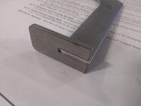
I'm making a lifting jig for some modules that weigh about 100 lbs.

The best way to describe what is looks like is the grabber used to pick up blocks of ice.

In this case, the module has a groove along the side....so my grabber has these tabs to fit in the slot. There will be 2 grabbers, one at each end of the module...so 4 feet...each one carrying around 25 lbs.

I'm thinking I can just mig weld the bottom...let the tab be a bit proud so I have cavity...then just flood the cavity with Mig weld.

Or do the sides on the top. I kinda just want to weld the bottom for a cleaner look. If I had access to a TIG, then I'd weld on top

The steel is 1/8" cold rolled.
 

Attachments

  • IMG_20200302_150102916.jpg
    IMG_20200302_150102916.jpg
    65.7 KB · Views: 226
  • IMG_20200302_150128764.jpg
    IMG_20200302_150128764.jpg
    73.9 KB · Views: 193
To avoid these ads, REGISTER NOW!

matt_i

Well-known member
Joined
Mar 14, 2008
Messages
10,726
Location
SE Michigan
With a nice tight joint like that I would silver solder (silver braze 56% with white flux).

It will flow thru it and fillet all of the surfaces without creating a fillet the size of a mig weld.

Also stronger than just plug welding the underside.

With a tig you could get a lot more melting before applying the filler rod whereas with Mig its just going there.
 
OP
D

ddawg16

Well-known member
Joined
Jul 11, 2008
Messages
21,005
Location
S. California
With a nice tight joint like that I would silver solder (silver braze 56% with white flux).

It will flow thru it and fillet all of the surfaces without creating a fillet the size of a mig weld.

Also stronger than just plug welding the underside.

With a tig you could get a lot more melting before applying the filler rod whereas with Mig its just going there.

Hmmmm.....hadn't thought of that......only downside, I'd have to go by the solder and find a torch....but, that would be a really clean weld.
 

95vette

Banned
Joined
Jul 24, 2011
Messages
119
Hello, Four good tacks will hold a hundred pounds, so good weld across the bottom will be fine.
 
To avoid these ads, REGISTER NOW!
OP
D

ddawg16

Well-known member
Joined
Jul 11, 2008
Messages
21,005
Location
S. California
If you haven't brazed before, I would not start on this project.

I have....I find it easy.....when you have the gear.


Sure, weld the bottom, fill it.

MIG- I'd turn the heat up and weave a nice wide bead across the bottom; no worries about burning through with the vertical member in the center.

Thanks for confirming what I really want to do.

My only issue....I'm stuck using what is available....Millermatic 252....loaded with 0.35 wire.
 

Wanna Ride

Well-known member
Joined
Jul 28, 2010
Messages
2,790
I’d weld top and sides. But then again, I have a habit of over-welding and over-building everything. With that being said, nothing I weld or build, ever breaks.
 

danielbuck

Well-known member
Joined
Apr 15, 2014
Messages
919
I’d weld top and sides. But then again, I have a habit of over-welding and over-building everything. With that being said, nothing I weld or build, ever breaks.

That's generally my stance as well. I'd rather spend more time making something probably more stout than it needs to be, than spend time fixing it later if it breaks.
 

MoonRise

Well-known member
Joined
Nov 5, 2010
Messages
4,028
Location
NJ
A MM252 with 0.035 solid wire on 1/8" cold-rolled steel?

Easy peasy.

You have PLENTY of welding power available. No bevels needed for that size material either.

A 175-180 class MIG with solid wire has plenty of amperage to weld 1/8" steel, a 200-210 class machine has more than enough, and a 250 class machine has way more than you need to weld 1/8" steel.

Just weld it up on the bottom. Not "flood the cavity" (you're NOT caulking a window frame Dawg! :lol: )

detailed steps if you need:

- clean parts of all grease, oil, paint, etc Plasma cut edges/faces should be cleaned up a bit before welding to remove the ever so slight surface oxides/nitrides (that hard nitrided surface layer can lead to porosity in the weld, no bueno for Code-quality welding work) that air plasma leaves behind, quick swipe with a file or abrasives is all you need to take off 5 thou or so (wire wheel on an angle grinder will NOT do the job here).

- assemble and clamp in desired position/orientation. I'd clamp it so the 'bottom' of the foot/plate is up and horizontal (welding position 1G).

- Two or three quick tack welds on the bottom and a few on the T as well to really hold it in place while you weld it. Check positioning after every tack weld, adjust as needed.

- Use short-circuit transfer mode, no need for spray mode on 1/8" steel or dealing with the really-really fluid puddle from spray mode (and the ~400 ipm WFS to get that wire size into spray mode! :lol ). Just regular C25 shielding gas, you'll probably be around 200-250 ipm WFS and 18-20 V with C25 and 100-150 amps. Plenty of power/heat to melt that 1/8" steel. Do a few test welds first. I'd do the weld 'flat' (1G position) and go from the 'outside' towards the 'inside' of the slot (your Pic #1, go from the right towards the left as you weld. Which works well for a righty welder, change the part left-to-right 180 deg if you are a lefty.). Small swirl/circle/E/whatever and you should be melting nicely into your workpieces. One pass is all you'll need on the bottom.

- If you really want to weld it up even more, then put the fillet welds in at the T. Both sides.

Welded on the bottom and with fillet welds on both sides of the T and your 1/8" straps will rip apart before the welds let go in almost any loading scenario I can picture.
 
OP
D

ddawg16

Well-known member
Joined
Jul 11, 2008
Messages
21,005
Location
S. California
Got them done......

Did a small tack weld....then checked for alignment....then welded.

I had the settings at 19.9/190. I wish I had some smaller wire...I had to go a little faster than I wanted to.

Then clean it up a little with a flap wheel.

This would have been a perfect task for TIG
 

Attachments

  • IMG_20200303_105248125.jpg
    IMG_20200303_105248125.jpg
    62 KB · Views: 111
To avoid these ads, REGISTER NOW!
Top Bottom