To avoid these ads, REGISTER NOW!

I think I found my winter project

grannyknot

Well-known member
Joined
Feb 13, 2021
Messages
84
Location
Toronto
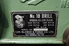
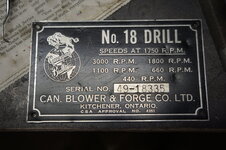
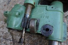
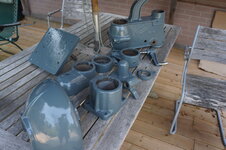
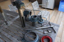
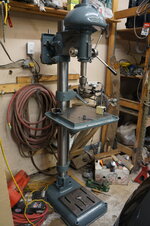
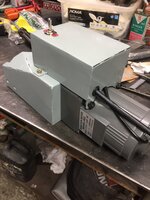
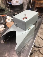
I have wanted one of the old Canadian Buffalo 18" drill presses for many yrs now and I finally just bought one today.
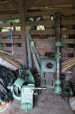
This thing is a monster, gotta be 400lbs at least, maybe more.
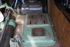
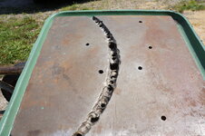
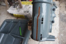
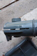
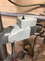
I think this unit must have spent a couple of decades in a High School metal shop, check out the "Arc of Shame" .:eek:
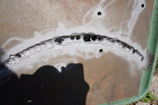
Looks like the little buggers deliberately tried to cut the table in half.
I'll have to bone up on my cast iron welding technique so I can fill in that trench on the work table. In fact this drill press is so heavy duty I may even be able throw a milling bit in the chuck and work the bulge of the welding repair job back down to flat.

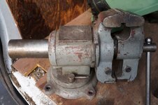
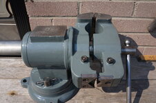
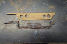
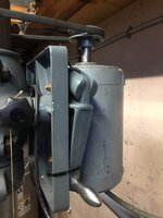
The old guy that was selling it was closing down his shop to retire, he threw in a beautiful big vice that he couldn't find a home for, it will find a good home in my shop!
 

Attachments

  • DSC00215.JPG
    DSC00215.JPG
    624.6 KB · Views: 246
  • DSC00216.JPG
    DSC00216.JPG
    630.9 KB · Views: 188
  • DSC00217.JPG
    DSC00217.JPG
    626.1 KB · Views: 189
  • DSC00218.JPG
    DSC00218.JPG
    772.5 KB · Views: 188
  • DSC00214.JPG
    DSC00214.JPG
    636.9 KB · Views: 189
  • DSC00219.JPG
    DSC00219.JPG
    813.8 KB · Views: 193
To avoid these ads, REGISTER NOW!
OP
G

grannyknot

Well-known member
Joined
Feb 13, 2021
Messages
84
Location
Toronto
Well this DP project might not last until the winter, I can't leave it alone.
I've taken the 1/2 hp motor apart and after cleaning and painting it's running well, very quiet.
Cleaned out all the muck out and sand blasted the arc of shame and it's even worse than I thought, I talked to a professional welder today who has lots of experience welding cast iron and he was not too eager to take the job on.
He suggested I fill it with braze instead, much less chance of cracking.
 

Attachments

  • DSC00223.JPG
    DSC00223.JPG
    819.4 KB · Views: 156
  • DSC00224.JPG
    DSC00224.JPG
    880.9 KB · Views: 140

txvwnut

Well-known member
Joined
Jan 1, 2015
Messages
7,624
Location
Bedford, Texas
My Walker Turner has a thick piece of phenolic attached to it. I decided one day to pull it off and see what was underneath. I couldn't get it reattached quick enough. My table looks about like the OP's. If you want to fix the arc of shame the best option would be to braze it as brazing doesn't impart too much heat into the table.
 

ChargerRT

Well-known member
Joined
Apr 20, 2015
Messages
152
Location
Louisville, KY
Man with an arc of shame as bad as this one what if you milled it out and put a piece of hardwood in there that matched the arc? this drill press restored and looking pretty would look pretty sweet with a sweeping arc of walnut
 

Davefr

Well-known member
Joined
Jan 7, 2010
Messages
11,832
Location
OR
Well this DP project might not last until the winter, I can't leave it alone.
I've taken the 1/2 hp motor apart and after cleaning and painting it's running well, very quiet.
Cleaned out all the muck out and sand blasted the arc of shame and it's even worse than I thought, I talked to a professional welder today who has lots of experience welding cast iron and he was not too eager to take the job on.
He suggested I fill it with braze instead, much less chance of cracking.
It looks horrible but I think it's structurally OK and won't crack in two. I'd buy a case of JB Weld and fill it up then hit it with a DA. Nothing you can do will make it an invisible repair. JB Weld isn't too far off color wise and will be easy to sand smooth/flush.

I just don't understand these arcs of shame. Back in the day these machines were expensive. Was every machinist a lazy hack?
 
OP
G

grannyknot

Well-known member
Joined
Feb 13, 2021
Messages
84
Location
Toronto
It looks horrible but I think it's structurally OK and won't crack in two. I'd buy a case of JB Weld and fill it up then hit it with a DA. Nothing you can do will make it an invisible repair. JB Weld isn't too far off color wise and will be easy to sand smooth/flush.
I have thought about JB weld or 3M epoxy panel bond, both would work but I'll try the braze first. I also like the idea of attaching a plate on top. You're right, structurally it's fine and I don't mind the repair showing, scars add character.
I just don't understand these arcs of shame. Back in the day these machines were expensive. Was every machinist a lazy hack?
I'm pretty sure this machine spent years in a high school shop, I know my HS shop teacher would roll over in his grave if he saw this damage. Every tool in his shop had to be back in its spot and pristine clean before anyone could leave.

I had a go at the chuck today, looks like it hasn't been serviced in a while, if ever. It is pretty banged up, might have to replace it.
 

Attachments

  • DSC00226.JPG
    DSC00226.JPG
    316.4 KB · Views: 140
OP
G

grannyknot

Well-known member
Joined
Feb 13, 2021
Messages
84
Location
Toronto
I think I'm going to choose to go the "do no harm" route and cover the whole table with 1/2" plate steel.
I've been doing a lot more reading and although the brazing route could work there is still the risk during the heating and slow cooling period of splitting the table. The different expansion and contraction rates of the cast iron and bronze worries me, could be completely wrong about this but I'm thinking because there will be so much braze fill the bronze might act like a wedge as the cast iron contacts around it.

I don't have enough experience in this area and if I do take it to a pro and the table splits, he's just going to say "sorry buddy".
Maybe I'll post this on the fabrication forum before I make a final decision.
 

Davefr

Well-known member
Joined
Jan 7, 2010
Messages
11,832
Location
OR
I think I'm going to choose to go the "do no harm" route and cover the whole table with 1/2" plate steel.
I've been doing a lot more reading and although the brazing route could work there is still the risk during the heating and slow cooling period of splitting the table. The different expansion and contraction rates of the cast iron and bronze worries me, could be completely wrong about this but I'm thinking because there will be so much braze fill the bronze might act like a wedge as the cast iron contacts around it.

I don't have enough experience in this area and if I do take it to a pro and the table splits, he's just going to say "sorry buddy".
Maybe I'll post this on the fabrication forum before I make a final decision.
I'd still start with the JB Weld route. It's pretty inexpensive and easy to do and would also add a tad bit of strength to that area without any risk. Then if you want, add a plate to the top. 1/2" plate steel that size will be expensive, hard to shape and very heavy. I'd go with 1/8"-1/4" plate aluminum drilled and tapped into the old table with countersunk stove bolts in all four corners. It can be cut with a jigsaw.
 

PSCo1867

Well-known member
Joined
Nov 11, 2020
Messages
306
Location
PA
Not knowing the actual composition of the drill-press components, I have to ask the question: Is there a chance that the "arc of shame" table is actually cast steel, instead of cast iron? I've been pleasantly surprised before with different repair dilemmas, and things become instantly repairable.

I'm guessing it's iron, but I thought I'd ask. In that case, I'd go for the braze repair.
 
OP
G

grannyknot

Well-known member
Joined
Feb 13, 2021
Messages
84
Location
Toronto
Did you add any fill to the “arc of shame”?

I’m going to follow along with your progress.
No I didn't, the table it self is plenty strong without any filler so I just screwed the plate down from underneath.
Not knowing the actual composition of the drill-press components, I have to ask the question: Is there a chance that the "arc of shame" table is actually cast steel, instead of cast iron? I've been pleasantly surprised before with different repair dilemmas, and things become instantly repairable.

I'm guessing it's iron, but I thought I'd ask. In that case, I'd go for the braze repair.
Steel would have been a breeze to repair, no, it's cast iron. Would have liked to repair it with braze too, then I watched this funny video.
 
OP
G

grannyknot

Well-known member
Joined
Feb 13, 2021
Messages
84
Location
Toronto
So what is waiting for me behind this cap, a razor sharp spring ready to jump out?
I loosened off the Allen screw and the whole cap spun counter clockwise a couple of revolutions.
Open to advice on how to proceed on removing the spindle and pinion.

Manged to get the tag off without damaging it and started cleaning up the pinion handles, I have some long end knobs coming from McMaster-Carr to help with leverage.
 

Attachments

  • DSC00235.JPG
    DSC00235.JPG
    664.4 KB · Views: 76
  • DSC00231.JPG
    DSC00231.JPG
    582.8 KB · Views: 49
  • DSC00232.JPG
    DSC00232.JPG
    763.2 KB · Views: 43
  • DSC00234.JPG
    DSC00234.JPG
    574.1 KB · Views: 46
  • DSC00233.JPG
    DSC00233.JPG
    535 KB · Views: 70
OP
G

grannyknot

Well-known member
Joined
Feb 13, 2021
Messages
84
Location
Toronto
Some success today, I got the head disassembled. Every video I've watched showed the spindle just falling out after the pinion was removed, not mine. I finally had to mount it on the press to make any headway, apparently someone in the past tried to disassemble by whacking the top of the splined shaft, that mushroomed out the top of the splines, that's why it wouldn't budge. I never would have have got it all apart without a press.
All 4 bearings need replacing.

The spring I was so freaked out about was very simple, no danger at all, cleaned out all the old grease with solvent, blew it dry and soaked it in a bath of 30wt oil over night.
 

Attachments

  • aug291.JPG
    aug291.JPG
    81.3 KB · Views: 41
  • aug293.JPG
    aug293.JPG
    111.7 KB · Views: 40
  • aug294.JPG
    aug294.JPG
    118.1 KB · Views: 36
  • aug295.JPG
    aug295.JPG
    114 KB · Views: 34
  • aug296.JPG
    aug296.JPG
    108.1 KB · Views: 52
OP
G

grannyknot

Well-known member
Joined
Feb 13, 2021
Messages
84
Location
Toronto
I stripped 3-4 layers of paint off everything and then painted a couple of coats of the closest grey I could find to the original, the new bearings came in today also.
Still have to strip the base and work on refinishing the main column, it's pretty rough, what I really need is to spin this column up on a lathe with 6ft bed.
 

Attachments

  • DSC00274.JPG
    DSC00274.JPG
    1.1 MB · Views: 36
  • DSC00272.JPG
    DSC00272.JPG
    1.3 MB · Views: 32
  • DSC00275.JPG
    DSC00275.JPG
    685.2 KB · Views: 33
  • DSC00267.JPG
    DSC00267.JPG
    619.6 KB · Views: 34
To avoid these ads, REGISTER NOW!

Jgaz

Well-known member
Joined
Dec 16, 2016
Messages
1,662
Location
AZ
Can you spin the column with a rubber pressure test plug seater in one end?
Maybe a plug used for large pipe coupled to an electric drill?
Use a threaded coupling nut on the end of the plug’s expansion bolt with a cut off bolt gripped in the drill chuck.

Support the ends of the column with a couple of casters on the bottom of each end.
Kind of like 2/3s of a steady rest.
 
OP
G

grannyknot

Well-known member
Joined
Feb 13, 2021
Messages
84
Location
Toronto
Can you spin the column with a rubber pressure test plug seater in one end?
Maybe a plug used for large pipe coupled to an electric drill?
Use a threaded coupling nut on the end of the plug’s expansion bolt with a cut off bolt gripped in the drill chuck.

Support the ends of the column with a couple of casters on the bottom of each end.
Kind of like 2/3s of a steady rest.

I like the way you think!
I have all of that stuff kicking around here, I'll have to see what I can hobble together.
 

RTM

Well-known member
Joined
May 13, 2019
Messages
13,166
Location
SF Bay Area
What makes you say that? This thing is old and made out of quality steel.
Cuz the good Chinese imports say something like this.

PXL_20240414_195418116-X3.jpg

The cheap ones say nothing.

The wing nut underneath locks the rotating bits

PXL_20240419_171531915-X3.jpg

The cheap ones use the main screw to lock both.

Look at the size of the cylindrical bit the main handle goes thru. There are some skinny ones out there, and probably a skinny screw too.


The US made ones have the brand cast in in raised letters maybe?

Mine is from the early 80s, you can see the mass of bondo and primer to make it prettier.
 
OP
G

grannyknot

Well-known member
Joined
Feb 13, 2021
Messages
84
Location
Toronto
Interesting, there's no wingnut/bolt on mine and the nut on the end of the main screw is castellated with a cotter pin so not sure atm what is locking the rotating assembly.
I'll probably reassemble it this weekend and will report back.

I guess "cheap Chinese" is a relative term these days, the difference between the build quality of this vise and the stuff being sold currently at Harbor Freight is night and day.
102 lbs for a 5"
 

Attachments

  • DSC00269.JPG
    DSC00269.JPG
    693.7 KB · Views: 36
  • DSC00270.JPG
    DSC00270.JPG
    328 KB · Views: 33
  • DSC00271.JPG
    DSC00271.JPG
    738.8 KB · Views: 37

RTM

Well-known member
Joined
May 13, 2019
Messages
13,166
Location
SF Bay Area
guess "cheap Chinese" is a relative term these days, the difference between the build quality of this vise and the stuff being sold currently at Harbor Freight is night and day.
102 lbs for a 5"
Mine is only 76# at 4.75”

They aren't bad vises. But I don't think they will have the durability or build quality of my Parker, my Reeds, the good old American iron
 
OP
G

grannyknot

Well-known member
Joined
Feb 13, 2021
Messages
84
Location
Toronto
Got it all back together and you're right RTM, the vise can rotate until it is clamped down on the work piece, then its locked.
 

Attachments

  • DSC00277.JPG
    DSC00277.JPG
    802.6 KB · Views: 26
  • DSC00279.JPG
    DSC00279.JPG
    600.1 KB · Views: 26
  • DSC00281.JPG
    DSC00281.JPG
    490.4 KB · Views: 32
OP
G

grannyknot

Well-known member
Joined
Feb 13, 2021
Messages
84
Location
Toronto
I got the column and base finished this weekend, the flat machined surface on the base will never be used for what it is designed for while I own it so I'm wondering if I shouldn't just put a couple of coats of paint on it and keep it nice for the next guy.
 

Attachments

  • DSC00291.JPG
    DSC00291.JPG
    1,001 KB · Views: 25
  • DSC00295.JPG
    DSC00295.JPG
    824.4 KB · Views: 36

SMOKEYBEAR

Well-known member
Joined
Jan 3, 2016
Messages
453
I knew I'd never use the base as intended on some I've brought back to life as well. I just taped the base off and sprayed the machined surface with a gray/ charcoal color so it had the "look" while in my shop without worrying about the rust returning.
 
OP
G

grannyknot

Well-known member
Joined
Feb 13, 2021
Messages
84
Location
Toronto
I have been fooling around with diy nickel plating hardware and fasteners, I've done zinc plating before which can be quite involved but nickel plating is much easier and I'm sure will last a long time.
It has a warmth to the look that you don't get with chrome.
In the 3rd pic the unplated steel piece is to the far right.
 

Attachments

  • DSC00303.JPG
    DSC00303.JPG
    89.4 KB · Views: 30
  • DSC00306.JPG
    DSC00306.JPG
    78.7 KB · Views: 25
  • DSC00299.JPG
    DSC00299.JPG
    926.8 KB · Views: 24
  • DSC00300.JPG
    DSC00300.JPG
    420.5 KB · Views: 25
  • DSC00301.JPG
    DSC00301.JPG
    443.7 KB · Views: 35
OP
G

grannyknot

Well-known member
Joined
Feb 13, 2021
Messages
84
Location
Toronto
There was a wooden spacer in the front of the head, could not get it out with out it breaking it, had some old very dense Mahogany on hand so made a replacement. The manufacturer painted over top of it but I thought it would add some "bling" to the machine.

I got most the drill assembled yesterday, it's a good thing I wasn't a day older, just about didn't get the head in place by myself.
The VFD is suppose to come in the next couple of days.
So far the runout seems to be about 11/1000th" which is a damned site more accurate than the outgoing drill press, once I get power to it and run in the new bearings at high speed I'm hoping things will settle out and might get a better number, or possibly not.
 

Attachments

  • DSC00313.JPG
    DSC00313.JPG
    510.4 KB · Views: 34
  • DSC00314.JPG
    DSC00314.JPG
    600.6 KB · Views: 29
  • DSC00315.JPG
    DSC00315.JPG
    630.4 KB · Views: 28
  • DSC00311.JPG
    DSC00311.JPG
    315.1 KB · Views: 29
  • DSC00310.JPG
    DSC00310.JPG
    690.9 KB · Views: 26
  • DSC00308.JPG
    DSC00308.JPG
    294.3 KB · Views: 25
OP
G

grannyknot

Well-known member
Joined
Feb 13, 2021
Messages
84
Location
Toronto
VFD arrived, Automationdirect DURApulse GS21-22PO, will easily handle the old 1hp 3ph I have.
Good company to deal with, good communication and techs who actually know what they are talking about.
 

Attachments

  • DSC00324.JPG
    DSC00324.JPG
    315.6 KB · Views: 14
  • DSC00325.JPG
    DSC00325.JPG
    357.4 KB · Views: 15
  • DSC00326.JPG
    DSC00326.JPG
    390.4 KB · Views: 28

Davefr

Well-known member
Joined
Jan 7, 2010
Messages
11,832
Location
OR
There was a wooden spacer in the front of the head, could not get it out with out it breaking it, had some old very dense Mahogany on hand so made a replacement. The manufacturer painted over top of it but I thought it would add some "bling" to the machine.

I got most the drill assembled yesterday, it's a good thing I wasn't a day older, just about didn't get the head in place by myself.
The VFD is suppose to come in the next couple of days.
So far the runout seems to be about 11/1000th" which is a damned site more accurate than the outgoing drill press, once I get power to it and run in the new bearings at high speed I'm hoping things will settle out and might get a better number, or possibly not.
Looks great!! Measure runout at the spindle.
 
OP
G

grannyknot

Well-known member
Joined
Feb 13, 2021
Messages
84
Location
Toronto
So she's up and running, I haven't managed to get the stop/start button working yet as it seems you either use the key pad to start/stop and vary the speed or you have to go completely to external controls so I would have to get a potentiometer as well.

The run out was 11 thou so I gave the spindle a sharp rap on the high side that bought it down to 7 thou and as soon as the drill press was running I took it up to full speed for about 10min and did lots of random little taps with a hammer on the spindle, it is down to 5 thou run out now and I'm pretty happy with that, maybe it will continue to improve as the new bearings wear in.
This machine is much quieter than the old one, I don't even need hearing protection anymore.
 

Attachments

  • DSC00369.JPG
    DSC00369.JPG
    446.5 KB · Views: 23

Davefr

Well-known member
Joined
Jan 7, 2010
Messages
11,832
Location
OR
So she's up and running, I haven't managed to get the stop/start button working yet as it seems you either use the key pad to start/stop and vary the speed or you have to go completely to external controls so I would have to get a potentiometer as well.

The run out was 11 thou so I gave the spindle a sharp rap on the high side that bought it down to 7 thou and as soon as the drill press was running I took it up to full speed for about 10min and did lots of random little taps with a hammer on the spindle, it is down to 5 thou run out now and I'm pretty happy with that, maybe it will continue to improve as the new bearings wear in.
This machine is much quieter than the old one, I don't even need hearing protection anymore.
When it comes to runout, there's runout from the spindle and runout from the chuck. If each component's runout is aligned in one direction it will be worst case. There's a trick called "indexing the chuck". You install the chuck so that it's max. runout point is opposite of the spindle so they tend to cancel each other out. (example: if the chuck is .005" and the spindle is .005" in the same direction total runout can be .010" but if you orient them 180 degrees from each other, runout could drop to .000".) It might be worth experimenting.

I hope that made sense. In any event .005" is perfectly fine for a DP. Nice job on the restoration. It looks like you need to line up another "winter" project.
 
OP
G

grannyknot

Well-known member
Joined
Feb 13, 2021
Messages
84
Location
Toronto
When it comes to runout, there's runout from the spindle and runout from the chuck. If each component's runout is aligned in one direction it will be worst case. There's a trick called "indexing the chuck". You install the chuck so that it's max. runout point is opposite of the spindle so they tend to cancel each other out. (example: if the chuck is .005" and the spindle is .005" in the same direction total runout can be .010" but if you orient them 180 degrees from each other, runout could drop to .000".) It might be worth experimenting.

I hope that made sense. In any event .005" is perfectly fine for a DP. Nice job on the restoration. It looks like you need to line up another "winter" project.
Thanks, I picked up a couple of projects today, a Logan 10.5"x24" model 200 lathe and a 15" production model Buffalo bench DP.
Both have been sitting in a barn for 20yrs so lots of work ahead.
 

Attachments

  • DSC00375.JPG
    DSC00375.JPG
    829 KB · Views: 15
  • DSC00374 (2).JPG
    DSC00374 (2).JPG
    260.5 KB · Views: 25
OP
G

grannyknot

Well-known member
Joined
Feb 13, 2021
Messages
84
Location
Toronto
The table on the drill press is 65lbs and more with the vise on top, my shoulders aren't what they were so I worked out how to motorizes it.
It's not much to look at but it does work well, I tie wrapped the original crank to the back in case the next owner wants to go back, if I hadn't then it would be guaranteed to get misplaced.
I used this motor from ebay, https://www.ebay.ca/itm/14620972161...IBwcEfllq1nl4VwTHAcutjAzbg==|tkp:BFBM2o7NoIxl
 

Attachments

  • IMG_1589.JPG
    IMG_1589.JPG
    616.2 KB · Views: 13
  • IMG_1590.JPG
    IMG_1590.JPG
    570.1 KB · Views: 11
  • IMG_1591.JPG
    IMG_1591.JPG
    525 KB · Views: 11
  • IMG_1596.JPG
    IMG_1596.JPG
    493.5 KB · Views: 16
To avoid these ads, REGISTER NOW!
Top Bottom