To avoid these ads, REGISTER NOW!

Inside Doc's Shop...

OP
D

DocsMachine

Well-known member
Joined
Sep 16, 2006
Messages
1,869
As we were talking about big boring bars earlier, during one such conversation, I idly checked eBay and almost immediately ran across a combo deal in my price range.

A Kennametal CNMG 1-1/4" diameter boring bar, with a hard-to-find Aloris CXA tool block that takes 1-1/4" bars. (Aloris only sells CXA blocks for 1" bars, today.) It was rusty and well used, but the seller was asking right about what the tool block itself usually goes for.

Even though finances aren't as flush as I'd like them to be, and I have no plans to do any heavy turning like that again in the near future... well, I'm still a tool geek at heart so I hit the BIN button. :)

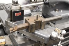
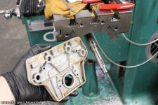
Here's what I got:

bigsteel18.jpg

It's not as bad as it looks. It's light surface rust, and only on the upper surfaces, so that tells me this spent some time in an unheated shop for a while- and overall, likely hasn't been used in many years.

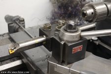
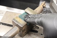
So first, I hit the mounting dovetail with some Scotchbrite and WD-40...
bigsteel19.jpg

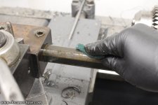
... So that I could mount it in the toolpost and break the clamping bolts loose. But first, I also scrubbed the rust off the shank of the bar...
bigsteel20.jpg

And once the locks were loose, she slid right out.

bigsteel21.jpg

A little more scrubbing and wire brushing got almost all the rest of the rust off, and a similar scrubbing on the tool block cleaned it up, too. Neither will ever look "new" again, but that's all right.

... Maybe I'll degrease 'em and try some gun blue. :)

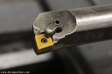
The nose of the carbide seat/anvil was, as is so typical, cracked off, so I simply reversed it. I have some new ones, but might as well use this one up before slapping one of those on.

bigsteel22.jpg

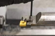
And, here's where things went sideways. :) The hex inside the clamping screw was almost completely stripped out.
bigsteel24.jpg

It had just enough grip to kind of seat, but wouldn't hold the wrench to loosen. I had to grab it with a vise-grips to get it back out.

Those I don't have a replacement for. If this was a time-crucial job, I could rob it from one of the square-shank tools, but in this case, I just ordered a two pack off eBay again.

Toying with the idea of getting the later model clamp, too, that has a longer nose and a pin that hooks that center hole. Not 100% sure it's compatible- this is a long-obsolete model of bar, but I may try. There's also a later style of pin that holds that lower anvil, and helps retain the insert through that same center hole. This bar wasn't designed for it, but if I can find an appropriate size pin, I may redrill and tap for it, to add the extra security.

But, overall, it cleaned up nicely, and I have no doubts it'd do another job like I just ran, with aplomb. :)

Doc.
 
To avoid these ads, REGISTER NOW!
OP
D

DocsMachine

Well-known member
Joined
Sep 16, 2006
Messages
1,869
A close call for Christmas, but Santa delivers! (And, a good illustration of why Doc is so hard to buy for. :) )

I'd actually ordered two different 1-1/4" boring bars back when I got the rusty one- but that one came Priorty, and this one came, I'm guessing, by dogsled, presumably pulled by arthritic corgis or something. The first one I got in part due to it being bundled with a now-rare 1-1/4" CXA toolblock, but this one is the better of the two bars.

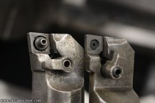
They're both Kennametal, but the latest one is a newer generation:

progress142.jpg

I have no idea when the changes were made- the older one could be 50-60 years old. But there's a couple of improvements: First and foremost, that center "pin" on the left-hand one (the 'newer' one) is a secondary retention for the insert. And second, how the reduced end of the bar on the newer one is both shorter and thicker- less metal was cut away. That makes for a stronger overall tool, with a better-retained insert.

That center pin is machined eccentric, and is turned to help lock the insert into its seat. (Note the arrow.)

progress143.jpg

The other bar is still a good, strong tool, but this one will be better for the really heavy-duty turning.

Also, I was lucky enough to find a second 1-1/4" tool block, giving me two complete setups.

progress144.jpg

I'm still going to need a good 1" bar, and possibly a dedicated 3/4" bar (not one borrowed from the Omniturn :) ) but those will come later.

Also, I splurged on a cute little 1/4-ton chainfall, that also finally came in:

progress145.jpg

So here in the hopefully not-too-distant future, I'll pick up some rollers and Unistrut, and get to designing that overhead trolley to lift, move and carry the chucks, and if necessary, heavy workpieces, too.

So... yeah. Shop toys I don't quite get to play with yet. :)

Merry Christmas!

Doc.
 
OP
D

DocsMachine

Well-known member
Joined
Sep 16, 2006
Messages
1,869
Years ago, I had to rob the VFD off of my Arboga drill press, after the old one blew out in my Logan lathe. I later bodged a temporary fix (likely going on it's fifth year :) ) by just stabbing in a spare WEG.

Boga001.jpg

Problem was, that was only good to 1 HP, and at the high setting, the drill was a 1.5HP. I also never got around to hooking up the stop/start buttons, so it was kind of inconvenient to use.

Today, as I was trying to make some headway into organizing the bomb crater that is my shop, I ran across the KB VFD I'd bought... three years ago? Specifically to install on this machine. I'd just put an identical one on my buddy's Scotchman saw a few months ago, so I had extra switches and cable piled near it.

Boga002.jpg

So, since I had a freshly-cleared off workbench, and I was getting tired of just moving stuff from one random pile to another, I dusted it off and started taking stock of what I had, and what I needed to do.

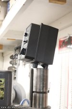
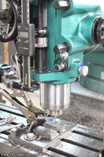
The big trick here, and has been since I got this drill a decade and a half ago, is to actually mount the VFD on the machine itself, rather than screwed to the nearest wall. The design of the drill doesn't give me too many options for mounting, though. I didn't want to put it down by the base, since the VFD has a power switch on it, and I wanted that and the speed control easily accessible. Ditto mounting it on the back of the column, facing away.

So more or less since the beginning, I've been toying with the idea of mounting it to the top of the column.

Boga003.jpg

Some sort of L-shaped bracket that bolts to the top of the column, perhaps... I have a couple sketches, but I may need to do some cardboard mockups. For example, the large middle boss of the VFD is where the heavy 3-phase cable comes in from the motor. I can't have that too low to the column, or the VFD too far forward, since the head can be raised on the column and could interfere.

On the other hand, the original design for this machine was the power cord came up the center of the hollow column, to connect to the controls. I'd like to do that to the 220V 1Ph feed to the VFD. There's a 'port' in the drill's base casting specifically to run a power cord into.

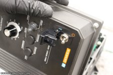
But, that's all for another time. I still need to get the whole shop into some semblance of 'tidy' and get the Capital-F back to work. So in the meantime, I prepped the VFD by first adding a cutoff switch and another one of the military-style switch protectors, just 'cause it's cool...

Boga004.jpg

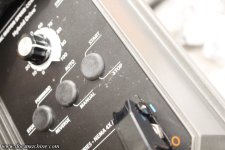
Then removed the start/stop switch, and corked the hole with the freshly-removed rubber plug from the power switch port. The buttons on the front of the drill press will do the start/stop, so no need to have it on the VFD.

Boga005.jpg

Stripping nearly a foot from the end of some 300V cable, I got the new power switch wired internally, and locked in with a weathertight gland.

Boga006.jpg

... Aaaand, that was about as far as I could go today. Next step, whenever that may be, will be to fab a mount- that's the tricky part. After that it's just wiring. Mostly.

Doc.
 
OP
D

DocsMachine

Well-known member
Joined
Sep 16, 2006
Messages
1,869
Well ****- like others have said, they don't make things like they used to. :)

Longtime readers will know that my main machine in the shop is my Grizzly mill- a Bridgeport clone I bought back in 2002. I've used this thing close to every day since then, putting many, many thousands of hours on it.

And today, for the first time, it broke. I barely got 24 years out of it! :D

I'd been doing a repetitive job using a fixture, that was a counterbore operation, using the quill like a drill press. I'd been noticing the quill didn't want to return all the way to the top of the stroke each time, and I was thinking the oil in there was maybe getting a little sticky. Since I was almost done, I figured I'd finish the job, clear off the table, clean the quill, etc.

Nope, I was setting up the last cutter and as I ran the quill down, something went "CRACK!" and the quill fell to the depth stop.

sproing1.jpg

Quill still moved freely, but no spring return, so clearly the 'clockspring' in the quill handle decided to take the day off. I opened it up and... sure 'nuff:

sproing2.jpg

sproing3.jpg

I figure it'd been cracked for at least part of this run, which probably explained why the quill wouldn't fully return. That last pull popped it the rest of the way.

I could finish the run without it, but it'd be tricky. I leave the spindle turning while I swap the part, and this way I'd have to rely on the quill lock. I may wait 'til I get a replacement in.

And that part, at least, isn't bad- this mill is a bolt-for-bolt copy of a Bridgeport, made in the same Taiwanese factory that used to make Bridgeports for... well, Bridgeport. (Now Hardinge.) As such, replacement parts are both common and ubiquitous. :) The new spring should be here by the end of the week, and I should be back up and running by then.

I suppose I'll just have to sit here and twiddle my thumbs 'til it arrives. :D

Doc.
 

SilverJimmy

Well-known member
Joined
Apr 14, 2012
Messages
1,643
Location
Prescott/Flagstaff, AZ
On my Ex-Cell-O mill that is a common failure also. Right after I got mine I read about the frequency of the return spring failing, looked into getting a spare, just in case…
I found a source selling them on eBay, cool, they’re available! About 6 months later I read that the guy making them was the OEM manufacturer of the springs, retired, ain’t making any more, and they are all sold, out of stock! The old saying, “You snooze, you lose!” hit me hard! I really hope mine doesn’t **** the bed. But, it really shouldn’t be that hard to make one….
 
OP
D

DocsMachine

Well-known member
Joined
Sep 16, 2006
Messages
1,869
Probably wouldn't need to make one from scratch, there's a lot of clocksprings you can get just off the shelf, if not being able to adapt something from another mill.

Heck, I'd be surprised if something like that from a Bridgeport wasn't damn near a drop-in. BP has been making these things since the thirties, and a LOT of manufacturers have copied their template to one degree or another.

Doc.
 
OP
D

DocsMachine

Well-known member
Joined
Sep 16, 2006
Messages
1,869
Mill's back up to full speed!

The new spring came in Friday, and I took a moment this afternoon to slip 'er in place. But first, I had to get rid of the old one:

sproing4.jpg

I set it up in the outside vise, and used a chunk of aluminum rod as a drift to tap it out. That way, when it inevitably exploded, it wouldn't break three windows, sever an important vein or two, and possibly startle the cat.

And explode it did:

sproing5.jpg

I guess I was expecting to unwind more, but either way, when it did, it did so with alacrity. :)

The new one arrived safely ******* and wired, so I set it back in the adjuster collar, and used the same drift to tap it into place- sliding the wire off as it went.

sproing6.jpg

Et voilá.

sproing7.jpg

Now, the trick is, that mounting collar is also an adjuster, you have to "wind" it to preload the spring. That is usually done with a pin spanner, except I don't have one- at least, not one that fit this application. I was also feeling a little lazy today, so I made a quick-and-dirty one. First, by turning a .210" spud on the end of a longish bit of 1/4" mild steel rod.

sproing8.jpg

With some aluminum pads, I bent the ends in the vise....

sproing9.jpg

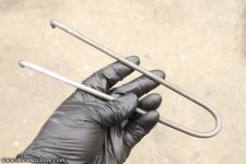
And then bent the whole mess in half.

sproing10.jpg

That let me hold and 'wind' the collar easily- which is a good thing, as it took a surprising lot of trial and error.

sproing11.jpg

This spring, unfortunately, apparently isn't as strong as the old one, and by the time I got enough tension on it to actually retract the quill as the old one did, it ended up going into coil bind halfway through the quill travel.

So I had to do a lot of back-and-forth to get the most tension, but not to the point it binds. And I eventually got there, but while there's enough spring tension to help the quill raise back up, it won't slide back up on its own anymore.

sproing12.jpg

Anyway, it's back together, and works fine, I'll just have to get used to manually raising the quill from now on.

And, with that buttoned back up, I was able to finish up the delayed project that was in the fixture, clean the table, re-check the tram, and move on to the next project. :)

Doc.
 
OP
D

DocsMachine

Well-known member
Joined
Sep 16, 2006
Messages
1,869
Too bad on the weak/improper spring.

-Thing is, none of the listings I checked (well, on eBay) said anything about spring rate or strength. The only difference was whether it was 25mm wide (which the old one was) or 30mm (which I don't think would fit.)

And looking at the photos, they all seem to have about the same turn count, so that pretty much just leaves thickness- and none look particularly thicker or thinner than others. (At least judging by the average eBay photo.)

I suppose I could try one from a different supplier and just hope that one's better, but for now, I may try re-tensioning it after it's had a chance to work in a bit.

Doc.
 

tool_scrounge

Well-known member
Joined
Jul 20, 2010
Messages
4,206
Location
Southern California
On my Ex-Cell-O mill that is a common failure also. Right after I got mine I read about the frequency of the return spring failing, looked into getting a spare, just in case…
I found a source selling them on eBay, cool, they’re available! About 6 months later I read that the guy making them was the OEM manufacturer of the springs, retired, ain’t making any more, and they are all sold, out of stock! The old saying, “You snooze, you lose!” hit me hard! I really hope mine doesn’t **** the bed. But, it really shouldn’t be that hard to make one….
Last time I was rebuilding a vintage drill press and could not find the correct width clock spring, I purchased a wider one and ground the tightly would spring down to the correct width. I had access to a precision wet laper so no chance of overheating it. But even with 80 grit carbide it still took a while,
 
OP
D

DocsMachine

Well-known member
Joined
Sep 16, 2006
Messages
1,869
Finally made a tool that I've been needing for years; a sliding adjustable fence for my bandsaw.

I use said saw a lot, with one of the primary uses being to slice up sticks of bar stock into smaller chunks to feed into the machines. For years I've measured and marked with a Sharpie, but this isn't terribly precise, and sometimes the cuts aren't all that square as I'm trying to wrestle a longish section getting cut. (That part I need a roller stand for, and that's coming.)

It's simply a cutting guide- it both helps keep the part square to the blade, and in this case, has a stop so you can cut repeatable lengths. Common stuff, they've been around since the advent of the tablesaw.

I'd been looking for a factory one for my DoAll saw, and it turns out there ain't no such thing. Well, there is, but what I wanted, doesn't really exist. There's fences (static walls a board or longer piece can ride against) and there's miter gauges (a sliding guide that can be set at a specific angle) and for a tablesaw, a sled (a sliding guide, often with a part stop) but I never found what I was looking for, for my specific saw.

I just needed a sliding fence with an adjustable stop on it, no need for the angle mitering, etc. If DoAll- or really, anyone else- made one to fit this saw, I never found it. Lots of shopmade versions, though.

I've been working on a largish run of parts, which has included cutting up a lot of material. I still had 20-30 feet to go (into nominally 6" sections) so I dropped what I was doing and finally made the damned thing. :)

I dug through the scrap pile and found a chunk of flame-cut steel that had enough meat to it, sawed off a section and proceeded to mill it into shape.

fence01.jpg

It was, as I said, flame cut (automatic acetylene torch) so it moved as it was cut- as stressed areas from unequal cooling were milled away, the part wanted to curve slightly. So I simply kept flipping it side for side, and eventually got a fairly straight bar. Then I faced the ends...

fence02.jpg

And checked it for a smooth sliding fit in the groove in the saw table:

fence03.jpg

I had a now-scrap part made out of some heavy angle aluminum, that was actually part of a table saw guide I'd made for a buddy of mine a number of years ago. He'd switched to a larger and more capable commercial unit, and so gave it back to me. The angle was an ideal piece for the fence itself:

fence05.jpg

So I drilled and countersunk a couple holes right about 'thar...

fence04.jpg

Drilled and tapped matching threaded holes in the steel guide bar...

fence06.jpg

And screwed 'em up. :)

fence07.jpg

With that assembled, I sawed the end off of the fence, in place to get the length right...

fence08.jpg

And then milled the cut edge smooth, which also added a touch more clearance to the blade.

fence09.jpg

Since the rest of the fence had had the corners rounded, I did so to the new bottom corner as well.

fence10.jpg

I then found a chunk of thinner angle and sawed off a section of that.

fence11.jpg

That got milled to height and slotted....

fence12.jpg

And then the fence drilled and tapped with a matching row of 3/8"-16 holes along the front face.

fence13.jpg

That of course gives me a place to bolt the length stop pretty much anywhere along the face- the holes are on 1" centers, and the slot in the stop is 1-1/2" long.

fence14.jpg

And with that, I set the length for the part in question, and proceeded to slice them into blanks of- for once- very uniform lengths.

fence15.jpg

And this is about 2/3rds of what I'm currently working on:

fence16.jpg

(They're stacked on the big mill since the Logan- the first machining step- is just to the left in that pic.)

Yeah, I should have made this thing years ago, but I've got it now, and I have no doubt I'll be getting a lot of use out it it from here on out. :)

Doc.
 

WoodsTruck

Well-known member
Joined
Jan 12, 2013
Messages
1,025
Are paint balls all a similar diameter?
Or are there some smaller caliber ones as well?
 
OP
D

DocsMachine

Well-known member
Joined
Sep 16, 2006
Messages
1,869
Quickie project from this morning, but first, my take on a meme, from breakfast:

poptart.jpg

:green:

Buddy of mine has a couple of the typical Asian minimills- one's a Little Machine Shop, the other I think... like a Busy Bee? Either way, they're square column mills, that raise and lower the head on a dovetail, either for milling or with a typical spider handle for drilling.

These come equipped with a clamp on the dovetail, which acts as a depth stop. In this case, the owner managed to break not one, but both. They're cast iron, and not ideally suited for that sort of stress, but also not available separately- the tech at LMS says he's never even heard of anyone breaking one.

progress001.jpg

He needed one to help with a repetitive project, so I whipped up a quick replacement.

progress002.jpg

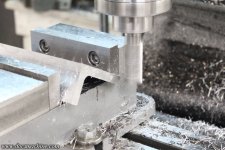
Now, the only tricky part of the whole thing being the mills have a 65-degree dovetail, and all my cutters have a much more common 60 degrees. McMaster has no 65 degree cutters, and every eBay listing is for a Chinese supplier- which would make sense. :)

Rather than waiting three weeks for a Chinese part, or ordering a $40 one-use tool from a US supplier if I can even find one, I dug into my collection of fly cutters, to see if maybe I could grind a workable substitute. As luck would have it, I found that some homebrew/shopbuilt thing, that I think came with a random mess of scrap from a garage sale years ago, held the stick of HSS at 65 degrees.

So I just had to grind the bottom edge and the backside for clearance. It's far from ideal- the cutter body puts the bar of HSS in the center of the axis, when it should have the leading edge on center. (Which, of course, depends on how you grind the tool.)

But it did the job, no waiting, no cash outlay. :)

progress003.jpg

I reworked the clamp to bolt together, rather than use the pinch screw.

progress004.jpg

The notch in the original was clearance for the rack, but in this case, he's using the stop near the bottom of the column, so for the sake of expediency, I left it off.

progress005.jpg

I'll probably make another with that notch when I have time, but this gets him back up and running.

Any other progress? Still just churning out blanks at the moment... There's two more bags behind me. :)

progress006.jpg

Doc.
 
Last edited:
OP
D

DocsMachine

Well-known member
Joined
Sep 16, 2006
Messages
1,869
Are paint balls all a similar diameter?
Or are there some smaller caliber ones as well?

-Technically both. 'Normal' paintballs are technically ".68 caliber", but there's .50 cal, .43, .40 and there used to be a .63. 68 is by far the most prevalent, .50 is used for "low impact" paintball games (typically for young kids) and the rest are used for basically airsoft type games or training.

But the trick is that in supposed '68 caliber', the paint size varies widely. Back in a day, paint might have been anywhere from .688" to .693", today it's often as small as .670"

And that can make a big difference in the accuracy and gas efficiency of the marker. They'll never be 'sniper rifle' accurate, but a small-bore ball down a big-bore barrel is noticeably worse than a close match. Too small a bore risks breaking the ball in the gun, which is bad news.

AND... a paintball is basically a glorified bath-oil bead or oversized vitamin-E capsule. The shell is gelatin, and is only going to be within a certain range of tolerance in the first place, with sizes varying between brand-to-brand and even box-to-box. There's also age and conditions- the shell soaks up humidity if you're not careful and can swell.

The upshot of all this is that any semi-serious player will have a range of barrels in slightly different sizes, depending on the day and quality of the paint. One option is what I'm making here- there's a commercial barrel system called the Freak, that takes thinwall insert tubes that come in a variety of sizes.

This is a 3-piece system; a back half, which holds the insert and screws into the marker, the insert itself, and a tip, which is basically just a fancy extended muzzle brake. Thing is, there's a bunch of older markers with proprietary threads out there, that no one makes the "back" half for- and those guns came with what are nor considered large-bore barrels.

So what I do is make short runs of specialty backs for those old and long-obsolete guns. That lets the players use that old gear with modern paint, and it's chaper than trying to manufacture a whole barrel.

Doc.
 
OP
D

DocsMachine

Well-known member
Joined
Sep 16, 2006
Messages
1,869
Playin' Catch-up!

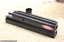
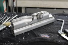
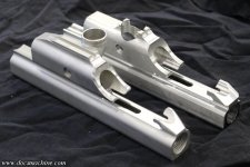
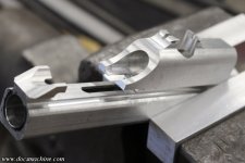
One of the oldest projects on the table right now is, actually, kind of a free one. A couple of years ago, we had a kind of raffle, and I offered to bump up the giveaway with a certain amount of airsmith time. :)

The winner and I pondered the options, and he settled on having me mill a 'Cocker body he had. The trick here is that we wanted to replicate the old "Fastback" milling, which was of course 3D profiled on a CNC mill. My CNC mill is still waiting for me to grow a suitable brain, so I did this the old fashioned way.

As many of you know, the Fastback was not my design- I just marketed and assembled them- so I didn't have the actual models and specs. I did, however, happen to have one of the original bodies, which I had bought back at great expense, and could therefore reverse engineer.

I decided to first try it out on a test dummy- a nearly literal scrap body, left from a batch I'd acquired years ago, where the shop had mistakenly tapped the front-block holes for 9/16"-18, rather than the 'Cocker's nonstandard 9/16"-24. Rather than scrap them, I cut most of them down to "MiniCocker" size and simply retapped the fitting for the correct screw.

I think I had two of them left, so I dug this one out:

fasty01.jpg

I gave it a rough sketch based off the original body, to show where I could saw off the bulk:

fasty03.jpg

Like so:

fasty04.jpg

Which saved a bunch of mill time. :)

The first tricky bit is the slot for the cocking sled, so I laid out in this kind of tricky setup, and predrilled some of it out...

fasty05.jpg

And then milled the slot to size:

fasty06.jpg

To get the signature curve to the back of the body, I employed a large Rotabroach, which was much easier than setting up the rotary table.

fasty07.jpg

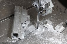
I later figured I could just RB that section out and make one bandsaw cut to wind up with pretty much the same effect. But for now, a little more milling got us to here:

fasty08.jpg

Milled a bit of the 'wings' off in front of the breech...

fasty09.jpg

fasty10.jpg

Rounded the edges of the pump slots....

fasty11.jpg

Milled the bolt-pin/cocking lug slot...

fasty13.jpg

Trimmed up the signature 'fangs' at the back...

fasty15.jpg

Clearanced the stub of the remaining sight rail....

fasty16.jpg

And that gives us a close approximation of the Fastback, just without some of the 3D milling/profiling yet.

fasty17.jpg

With those specs close enough I had reasonable confidence in them, I took the customer's body...

opusx-01.jpg

And dunked it in the lye bath to strip the anno off.

opusx-02.jpg

opusx-03.jpg

Finally, using my new knowledge, milled the same slot and took that big Rotabroach slice. :)

bite.jpg

To Be Continued!

Doc.
 
OP
D

DocsMachine

Well-known member
Joined
Sep 16, 2006
Messages
1,869
All of the above was.... a bit longer ago than I'd care to admit- although in my defense, it was also essentially 'free' work, and partly my own project. :)

This weekend, I dusted them off, and here's what we had- not shown from before, I'd also started blanking the cocking sleds:

fasty18.jpg

The majority of the body milling was done, so it was time to do some of that aforementioned 3D profiling. Like the Vee-Twin I made a couple years ago, that means hand filing.

I hold the body in a vise for this- I used to use pads that go in the jaws of the vise and are held magnetically, but I've had trouble with the weak-sauce magnets letting 'em flop off all the time. So these days I use proper soft jaws. Pop the old steel jaws out...

fasty19.jpg

Quick-like-a-bunny shave a few thou off the soft jaws to get rid of any dings or dents from the last job...

fasty20.jpg

And bolt 'em in.

fasty21.jpg

That holds the body solidly- and to my thousand-pound welding table :) - and the jaws won't mar the body. Starting with the rear 'fangs', I slapped on a little painter's tape to help protect against errant file strokes.

fasty22.jpg

fasty23.jpg

fasty24.jpg

I marked and lightly scribed a couple of guide lines for the bevel around the bolt shroud, and carefully worked my way along those, too.

fasty25.jpg

Et voila! Not quite as fancy as the original, but not too darn bad.

fasty26.jpg

Then, my 'scrap' body...

fasty27.jpg

fasty28.jpg

fasty29.jpg

Still not done- to be continued!

Doc.
 
OP
D

DocsMachine

Well-known member
Joined
Sep 16, 2006
Messages
1,869
These posts don't necessarily show everything in order- this particular project has been a bit all over the place, as I'm trying to juggle half a dozen flaming chainsaws at the moment. :)

I've been trying to post this stuff in what at least appears to be a logical order, but don't be fooled- it's a bit of a madhouse in here right now. :)

Anyway, since I'd already made this one already-long-overdue project even longer by adding my own parts to the pile, I figured one more couldn't hurt. So I dug this out and dusted it off.

fasty30.jpg

That is, or was, supposed to be a sort of "Fastback 2.0". Years ago- around 2007? I ran across a local guy that had a HAAS MiniMill in his garage, and was making some products of his own. I loaned him one of the last original Fasty bodies I had at the time, and he tried to reverse-engineer it.

Long story short, I couldn't really afford to have him CAD it up properly- and of course 3D scanning wasn't really a thing either of us could afford- and, after the one test part, we realized that even with a discount, the per-body cost was going to be astronomical. I can't even recall what this cost me all told, but I bet I could have bought a Westwood with it, at the time.

Anyway, I've had the body sitting around ever since. I did some of the secondary machining- the breech threading, the feed neck threading- LED Angel, natch, 'cause that was the hot ticket at the time :) - and so on. I even made a cool one-piece MiniCocker front block with integrated ASA for it:

fasty31.jpg

What I never got around to was making the cocking sled, pump rod, hammer, etc. I have to do that for these other two bodies anyway, so I figured this was a good time. I already had the other two sleds mostly made, but they still needed to be finished, and I'd still need bolts, rods and so on.

One tidbit that tripped us up early on, was the guy had drawn his CAD part from a blank, heavily modified body. He didn't have any factory-body specs, which for most of it wasn't a problem, but he didn't know about things like the necessary clearance for the pump rod. So the first thing I did was open up the side groove he had, to proper body specs.

fasty32.jpg

With that done, I started on the cocking sled itself. Thinned and stepped...

fasty33.jpg

Rounded on both ends...

fasty34.jpg

The pump rod hole properly located- thanks to the fresh body groove- and drilled and tapped.

fasty35.jpg

Finally, there were a couple of trimming steps to make it match the body profile:

fasty36.jpg

Assisted by a little file fine-tuning, et voilá!

fasty37.jpg

This body, too, will need a little finishing with a file, and that's coming up. In fact, lots more coming up- stand by!

Doc.
 
To avoid these ads, REGISTER NOW!
OP
D

DocsMachine

Well-known member
Joined
Sep 16, 2006
Messages
1,869
Didn't have much time for this one, today- I'm juggling a number of chainsaws at the moment. But, as the next bite on this elephant, I fabbed up the pump rods. Each body set is fairly unique, so I had to fit each one, TO each one. After a few rough measurements, I cut three pieces of 3/16" stainless rod, and faced and beveled each end.

fasty38.jpg

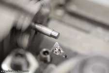
Then I set up the Geometric Die Head (the same one from fifteen years ago! :) ) on the Rivett turret lathe...

fasty39.jpg

And in just a few moments, had each rod threaded.

fasty40.jpg

The right one's a bit long, I adjusted the depth for the other two. Not shown, but I turned the long one down a tadge- that's a technical term- to match the others.

fasty41.jpg

I measured each one in place on their respective bodies, marked 'em, and cut 'em to length- this time on the Sheldon lathe.

fasty42.jpg

Back to the turret, I set it up to centerdrill, and then tap drill each one...

fasty43.jpg

(You can't beat a turret for drilling on a lathe. :) )

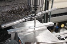
And then with a good sharp gun tap and some Tap Magic- which I don't usually use, but this is a tiny tap in stainless steel- cut each one to 6-32.

fasty44.jpg

And the last trick, I got out my custom-made rod bender.

fasty45.jpg

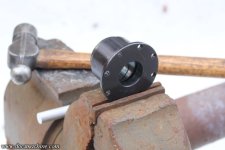
Years ago, everyone- including yours truly- was halfblocking and midblocking AutoCockers, which required either shortening original rods or making a new one from scratch. I made a ton over the years, and early on, I whipped up this press to get just the right 'dogleg' bend in one easy motion.

Just lay the rod in the groove, mach it in the vise or a press...

fasty46.jpg

And presto, one perfect bend in just seconds.

fasty47.jpg

And that's all three fitted.

fasty48.jpg

They may need fine-tuning when it comes time to assemble the guns for real, owing to differences in both front blocks and rams, but you occasionally have to do that even with factory parts. These basic markers have been in production one way or another for almost forty years, and by at least two dozen different companies. :)

We're nearing the end on this one! We just need bolts, pins and hammers!

Stand by!

Doc.

 
OP
D

DocsMachine

Well-known member
Joined
Sep 16, 2006
Messages
1,869
This part came out exactly as I intended....

progress008.jpg

... and it's scrap. :)

On the plus side, the monster hogged right through that in no time, that's only about ten minutes' work. Would have been over an hour on the little lathe...

But, just means I gotta do it again tomorrow...

Doc.
 

larry4406

Well-known member
Joined
Jan 27, 2006
Messages
19,438
Location
Northern Virginia
Nice fab!

That geometric die head is intriguing. Looks like it has 4 dies similar to a pipe threading die. It appears they retract when the thread is cut?
 

545_days

Well-known member
Joined
Oct 30, 2016
Messages
585
Location
Texas
I was intrigued by the geometric die head and fell into a Google rabbit hole. Mr. Pete did a video about these here:

I ended up on ebay pricing them. No surprise that would happen to someone on Garage Journal.
 

loganb

ALLIANCE MEMBER
Joined
Dec 29, 2011
Messages
5,577
Location
Omaha, NE
I was intrigued by the geometric die head and fell into a Google rabbit hole. Mr. Pete did a video about these here:

I ended up on ebay pricing them. No surprise that would happen to someone on Garage Journal.
So when does it show up? One does not simply "fall down the rabbit hole" on GJ without buying something during the fall :)
 
OP
D

DocsMachine

Well-known member
Joined
Sep 16, 2006
Messages
1,869
That geometric die head is intriguing. Looks like it has 4 dies similar to a pipe threading die. It appears they retract when the thread is cut?
-Yep. On a turret like this, you simply gently feed in the turret 'til it hits the stop, the head keeps "screwing itself" forward a bit, at which point it unlocks and retracts the dies. Hit my link- I had a quick and dirty video up on it 15 years ago- this same one, in fact.

They're still used today, especially on smaller diameters like this- they're still faster than even CNC single-pointing.

Doc.
 
Last edited:
OP
D

DocsMachine

Well-known member
Joined
Sep 16, 2006
Messages
1,869
Holy ****, that's a hell of a deal. I mean, I'd bet dollars to donuts the final sale will be much higher than that, but five heads, and a hundred boxes of chasers...? Heck, just that sharpening fixture usually goes for the current bid.

Too bad I don't need more of these things. :)

Doc.
 
OP
D

DocsMachine

Well-known member
Joined
Sep 16, 2006
Messages
1,869
Yeah, yeah, ain't dead yet. Had to do a bunch of side projects and catch-up bits. All of the following took place over parts of about three different days.

First, I recut that eccentric bit, but this time with the spud a bit closer to the center.

vtfb01.jpg

Like so.

vtfb02.jpg

Now, while the big monster is an accurate lathe, it's not what you'd call delicate. So I took the part over to the Sheldon and recentered it.

vtfb03.jpg

That spud then got drilled, bored and threaded.

vtfb04.jpg

Making it into an ASA- for you non-paintballers, an air system adapter, how we get pressurized air into the marker.

vtfb05.jpg

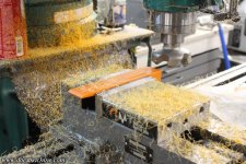
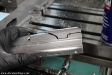
After that, and with a bit of careful eyeball alignment, it was time to hog off a ton of the excess meat.

vtfb06.jpg

vtfb07.jpg

Now that I had some square faces and still had a little extra metal, I located and started drilling the features.

vtfb08.jpg

vtfb09.jpg

This is actually the backside of the block. I counterbored the O-ring groove basically out of habit. :) But, that meant I had to clearance for the body...

vtfb10.jpg

vtfb11.jpg

And with that done, mill off even more of the excess.

vtfb12.jpg

vtfb13.jpg

A quick test fit...

vtfb14.jpg

And finally milling down that upper section.

vtfb15.jpg

Leaving us with this.

vtfb16.jpg

It's not quite done yet, it still needs a few finishing touches, but should be ready to ship out by Monday. :)

Doc.
 
OP
D

DocsMachine

Well-known member
Joined
Sep 16, 2006
Messages
1,869
They say the difference between a good machinist and a great one is the great one knows how to hide his mistakes better. :green:

Keep that in mind. :)

Today's task for this front block (for you non-paintballers, it goes to one of my Vee-Twin Autocockers) is to just clean up the milling, drill the internal air port, sand a few bits smooth, and mail 'er off. The main part being the blend between the ASA and the body of the block, so I milled away the bulk of it, trying to make sure I didn't go too deep.

vtfb17.jpg

Then I very gingerly filed the rest down to match the profiles.

vtfb18.jpg

I'm no Clickspring, but I know my way around a file. :)

vtfb19.jpg

Then we needed to open up some clearance for the 3-way linkage...

vtfb20.jpg

And then the very last machining step was to drill an air passage through from the ASA to the center bolt. It's a fiddly job, and unfortunately I didn't realize the drill was wandering a bit.

And I f**king ruined it.

vtfb21.jpg

It might be hard to tell from the photo, but the air passage breaks through the seat where the O-ring is supposed to seal, and you can see below that where the metal is now paper thin and pushed out. It's basically unrepairable.

I calmly and coolly came up with a few choice invectives and I may have hurled a few things. BUT... while moving to Tibet and becoming a monk is looking better by the day, this was still a job I needed to finish. I contacted the customer, offered a couple of options. One was to make it fresh from scratch- same cost, I don't charge for my screwups. I wish I could, I'd be a friggin' millionaire by now. :)

I also have another block with an integral ASA, from the original VT run, but the customer wanted a 15-degree rearward tilt, and the one I had was straight. Last, and what we settled on, was welding up the damage and remachining it.

The welded areas will show up in the anodizing, but in this case, the welded area will be between the block and the body, and can't be seen in use. So I milled the damaged area out...

vtfb22.jpg

TIG'ed the groove shut...

vtfb23.jpg

Remachined the whole mess...

vtfb24.jpg

And finally, very carefully and gingerly redrilled the air passage. Before I send it off, I'll mount and pressurize it to make sure there's no pinholes- there shouldn't be, but you never know.

After that, I scrubbed and wet-sanded it, and assuming it passes a pressure test, it's ready to go!

On to the next thing! :)

Doc.
 
OP
D

DocsMachine

Well-known member
Joined
Sep 16, 2006
Messages
1,869
Pressure test 100% successful.

vtfb27.jpg

Installed it on a body, threw a gauge in the LPR port, and hit it with full CO2 pressure. (Which, since it's only in the mid-60s in my shop, meant about 600 PSI.) Nary a bubble when I hosed it with some Windex. I think we can call this good! :)

Doc.
 
OP
D

DocsMachine

Well-known member
Joined
Sep 16, 2006
Messages
1,869
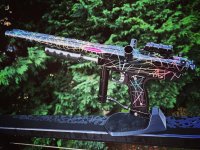
I machined the body and necessary parts, the customer had it anodized and added the finishing parts like the grip, regulator and barrels, but here's a shot of the gun that block is going on.

The original customer ordered it as a pump gun, but the new owner wanted it as a semiauto. So this block adapts it to take the pneumatics that make it so- a small LPR (low pressure regulator) a spool valve called a 3-way, and a small pneumatic ram.

Doc.
 

Attachments

  • headshot.jpg
    headshot.jpg
    225.8 KB · Views: 42

Xti04

Well-known member
Joined
Nov 11, 2016
Messages
2,338
Reading your thread has made me very nostalgic for a cocker. I looked up WGP and I guess they dont sell a complete gun anymore? I bought 2 autocockers back in about 03 or so, used to run a mini golf course with paintball and go karts. I saw a bunch of used markers on ebay, and they have not gotten any cheaper over the years for sure. I love that you still make parts for them!
 
OP
D

DocsMachine

Well-known member
Joined
Sep 16, 2006
Messages
1,869
WGP is gone. They- the original company- got bought out years ago, eventually passed through a couple of other companies, and was closed/liquidated probably close to a decade ago.

I'm not sure if anyone's making a new ready-to-go 'Cocker these days. Inception Designs was up until recently, but the market's pretty well saturated at this point. You can find jillions of them used- just look up "autococker" on eBay and keep scrolling 'til you find one you like. :)

Doc.
 

545_days

Well-known member
Joined
Oct 30, 2016
Messages
585
Location
Texas
Holy ****, that's a hell of a deal. I mean, I'd bet dollars to donuts the final sale will be much higher than that, but five heads, and a hundred boxes of chasers...? Heck, just that sharpening fixture usually goes for the current bid.

Too bad I don't need more of these things. :)

Doc.
Even more holy ****... It sold for $414.

I would have bought it for more than that just so that people on Garage Journal could tell me how much I ****. I just never dreamed it would...
 
OP
D

DocsMachine

Well-known member
Joined
Sep 16, 2006
Messages
1,869
Still makin' progress, just a lot of it at the moment is repetitive bulk-work. :)

Had a friend offer me most of his endmill collection. Seems his machine, an older Milltronic, has gone kerflooey- something with the drivers, which I took to mean the servo amplifiers. It'll cost too much to fix- more than the machine's worth- and he has machines at work he can use, so he doesn't need all the tooling.

progress014.jpg

Almost all carbide and less than $8 each- which was actually a bit more than he was asking, 'cause I'm a nice guy. Everything in a square tube is brand-new, and the rest are damn near. :)

And, interestingly enough, right when I was thinking I need to get some fresh tooling. I still want to buy up some basic HSS, but all this is a pretty nice start.

Much of the rest of the weekend was running the bejeebers out of the Omni:

progress015.jpg

I haven't been putting in nearly enough time on this yet this year- trying to get other way-overdue stuff taken care of. But I've got a boxful of product I've been needing to get off to anno since the beginning of the year, and I need another few dozen to fill out the order.

I also made one of these:

progress016.jpg

Actually, I started on three of them. :) They're not done yet, but I had reason I needed to at least start on them. More on what they are later- at least one of them may well be a very long term project.

And, while the Omni's been running- a 2:15 cycle time- I've been trying to clean up a little and put away tools, as the shop is a freakin' wreck. I had a heap of scrap metal, clean steel I occasionally use for this or that, but I haven't really had a place to put it. While I was trying to sweep the area, I got an idea. I had this chunk of treadmill base- particle board- that I'd used as a backing for the holesaw when I made the Rivett collet drawer.

progress017.jpg

It had no other use, so I cut it to length, nipped a couple notches in it, and fitted it to the base of the hydraulic press:

progress018.jpg

There's a crossbar under there to keep it from sagging too much. I'd already been kind of piling scrap there, often just as press tools- anyone with a press knows what I'm talking about. :)

This let me un-jumble it, make it a little easier to find stuff, and made more room for all the other pile. That opened up a fair chunk of floor, and like that game with the sliding tiles, made room to shift and organize a few other things, too.

The downside is the actual press tools no longer have a home. Really, I need to get rid of that grinder seen to the left, and make myself a little rack or something for it all.

Just one more thing for the to-do list...

Doc.
 
OP
D

DocsMachine

Well-known member
Joined
Sep 16, 2006
Messages
1,869
For the past couple of days, I've been running several baskets of parts on the Logan, my little CNC-converted lathe. As I've complained before, said lathe is slooooo-oow. With a max spindle speed of only 1,400 RPM, the shorter of the two types of parts I was running took just under six minutes, and the longer, just hair over eight.

Because of needing to keep "birds nests" of swarf off the work, and since the machine has no flood coolant, needing to periodically manually squirt it with a little WD-40, I can't just press the button and go do something else for six to eight minutes. So, I did what I could while I had to babysit. I cleaned off the Nichols horizontal, which was still set up for a part I last ran a year ago. And there have been times I wanted to use it, but didn't have or want to spend the time to break down that setup.

It's back to a regular vise, and once again usable at the drop of a proverbial hat.

One other thing that had bugged me for literal years, was the Exacto mill, which is just adjacent to the Logan. I'd pretty fully rebuilt that about a decade ago, but one thing that annoyed me and eluded an easy fix, was there was some slop in the manual quill downfeed handle. Basically what you yank on to use it as a drill press.

And that was the issue- the pressure of drilling took up that slop, but as soon as the drill "broke through", it jumped down a little due to the slop, and the drill could grab. I've broken drills that way, and one of those damaged the part.

So, while I was standing there twiddling my thumbs (the doctor said I should get more exercise) I cracked open the downfeed mechanism.

Zacto01.jpg

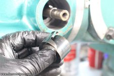
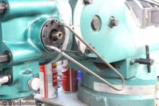
Now, it wasn't as easy as that- it was the same process as repairing the clockspring on the green mill a couple months back, but in this case, the spring holder didn't actually have any holes for that 'spanner' wrench. Initially, I held it with a big pair of Channeloks, but of course I wanted something better for the reinstallation.

So I drilled a pair of holes in the spring housing....

Zacto02.jpg

... So I could use that same ad-hoc spanner wrench from the other mill. Worked a treat.

Zacto03.jpg

After some diagnosis- not helped by having to attend to the lathe every 2-1/2 minutes- I determined that the pinion gear was loose on the shaft. Both the gear and the key had worn.

Zacto04.jpg

So I got out some key stock, and milled down a fresh, but slightly oversize key:

Zacto05.jpg

Zacto06.jpg

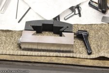
Zacto07.jpg

Since the gear had some wear too, but the hardened shaft was fine, I had to make a slight step in the key, being very careful to keep the tolerances tight. I wanted a light-to-moderate press fit, for zero slop.

Zacto08.jpg

And it worked great. I used the smooth face of the mill vise to press the key into the shaft, and it held well enough that, since it was a teense too tall, I was able to mill it down a few thou with no issue.

Zacto09.jpg

The gear itself had to be lightly tapped into place with a padded hammer...

Zacto10.jpg

Then cleaned, regreased and reinstalled.

Zacto11.jpg

And, while no picture can show you the lack of slop, the whole process was worth it- almost all the extraneous movement is gone. :)

Zacto12.jpg

Much better drilling action- well worth the effort. The kind of thing I wish I'd done years ago. :)

Doc.
 
Last edited:
OP
D

DocsMachine

Well-known member
Joined
Sep 16, 2006
Messages
1,869
Coming down to the last parts I need to run on the Logan- down to a dozen or so, but after the day of running, I didn't feel like resetting the machine again. I'll kick those out tomorrow, and then start feeding the Omni.

One thing I did get done was dusting off another mod for the Exacto. The two main upgrades I've wanted to do to this mill have been to add a DRO, and a new power feed. The DRO was the best mod I ever did on the green mill, and these days the main reason I default to it rather than the Exacto. :)

But for the moment, the first part I started looking into was the power feed. This machine originally came with one from the factory, but it was a monstrous 100+ pound cast-iron thing with a 3/4HP 3-phase motor. The drive gears were destroyed when I got the machine, and I've always presumed somebody had let it run up against the physical stops, and the brass/bronze gears were the first to let go.

Instead, I plan to install a modern "Servo" type drive like most home-shop mills come with these days:

Zacto13.jpg

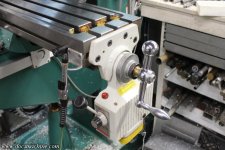
To keep the working travel of the table even with that huge factory power feed, Exacto added a long table extension to allow the full movement.

Zacto14.jpg

According to all the pics I've seen, there should be a handle there, but presumably it was removed at some point, I'd guess so the spinning handle didn't interfere with the next machine in the row, maybe?

Anyway, take that big extension off, and that leaves me a solid 8" of leadscrew I can turn down to Bridgeport spec in order to use an off-the-shelf Servo feed.

Zacto15.jpg

It's unfortunately not quite that easy- the bolt pattern at the end of the Exacto table isn't the same as a Bridgy, and it's a full 3" wider. So I ordered- several years ago- a block of Dura-Bar cast iron, which I'll machine down as a copy of the mounting plate- a hybrid between the Servo mount and the Exacto table.

Zacto16.jpg

It's gonna be a bit tricky, and I only get one chance (unless I order another $200 in iron, or $175 in aluminum :) ) but after a quick teardown and close measurement, I at least have the specs for the screw. So I can yank that and trim it down anytime I have a free half-day or so. :)

I also dusted off the DRO parts and opened those up for the first time- since I ordered them in early 2024. Both will be attended to as time permits, stand by. :)

Doc.
 
To avoid these ads, REGISTER NOW!
Top Bottom