To avoid these ads, REGISTER NOW!

interlock generator switch 2 main panels

sdowney717

Well-known member
Joined
Mar 17, 2010
Messages
964
http://www.interlockkit.com/croushndsmain01.htm

At my parents house there are 2 Crouse Hinds main panels each with 2 200 amp main disconnect breakers.
The second panel runs the well pump and the barn and the heat pump and electric heat with air handler

What I was wondering was if you can use 2 interlock kits, one for each breaker panel.
Run the generator breaker wires to a box and wire them together and have ONE gen set running both panels.

I understand that the house is a 400 amp single phase service.
The idea is when the power goes out to run what is needed except for perhaps the oven and clothes drier. The well pump will have to run and that breaker is on the other panel for some reason.
 
To avoid these ads, REGISTER NOW!

mrb

Well-known member
Joined
Dec 31, 2008
Messages
3,734
im not sure how kosher that would be. You would have a neutral looped between the two panels which i think is not ok. best thing to do in this scenario is put a 400a service rated manual transfer switch ahead of the two panels. Or rearrange your loads to get everything you want generator available to on one panel.
 
OP
S

sdowney717

Well-known member
Joined
Mar 17, 2010
Messages
964
that is interesting. The panels could be reworked to put what is needed on the one panel.

I seem to remember when wiring up the 400 amp service at a friends house, the neutral connection point was part of a bus inside the large long meter base.
So at his house, both panels ran the neutrals back to essentially the same connection point in the meter base, with the aluminum service neutrals from both panels on adjacent lugs.
 

mrb

Well-known member
Joined
Dec 31, 2008
Messages
3,734
that is interesting. The panels could be reworked to put what is needed on the one panel.

I seem to remember when wiring up the 400 amp service at a friends house, the neutral connection point was part of a bus inside the large long meter base.
So at his house, both panels ran the neutrals back to essentially the same connection point in the meter base, with the aluminum service neutrals from both panels on adjacent lugs.

right. but you have to have a neutral from the generator to the panel. if you connect each panels generator input together then you have another neutral connection between the two panels. thats not allowed and current will flow between the panels on it. of course the neutrals supplying the panels are connected together wherever they originate from, that is correct and doesnt make it ok to have another neutral connection between the two panels
 
OP
S

sdowney717

Well-known member
Joined
Mar 17, 2010
Messages
964
likely the easiest cheapest solution is simply move the well pump over to the other panel.

although it is strange for me to think the neutral currents flowing through 2 separate return paths instead of one is a safety issue (maybe a code issue only?). Is this because both genset breakers would use say an 6/3 wire from each panel?
What if one panel had an 6/3 wire and the other a 6/2 so the other panels neutral would return current through its original neutral to the meter base bus bar to the genset?
 

mrb

Well-known member
Joined
Dec 31, 2008
Messages
3,734
likely the easiest cheapest solution is simply move the well pump over to the other panel.

although it is strange for me to think the neutral currents flowing through 2 separate return paths instead of one is a safety issue (maybe a code issue only?). Is this because both genset breakers would use say an 6/3 wire from each panel?
What if one panel had an 6/3 wire and the other a 6/2 so the other panels neutral would return current through its original neutral to the meter base bus bar to the genset?


cant do your 6/3 and 6/2 scenario. All circuit conductors have to be in the same conduit or cable. Cant have your hots in one cable and get the neutral from somewhere else
 

ket-tek

Well-known member
Joined
Jan 28, 2009
Messages
1,289
This is pretty much my exact same situation, 400amp incoming to the meter and 2x 200amp panels out of the meter. I want to install a manual transfer switch between the meter and 2 panels so that I have full choice of using anything in either panel on the generator.

I had originally planned to use 2 interlock kits and having a the gen feed split and feed both panels. I've gotten conflicting info from local electricians as to if splitting one feed to two panels is legal, safe, or doable. The service feed is split so why can't the gen feed?

But recently I've been looking at something like this, replacing my meterbase with one that has a built-in transfer switch. It seems to be the most straight forward way to do such a high amperage load.

Still need to more research if I am thinking properly on this..

7406-MS-2.jpg
 
Last edited:

mrb

Well-known member
Joined
Dec 31, 2008
Messages
3,734
to clear something up: you can split the generator feed, its done all the time in commercial installs but transfer switches that also switch the neutral are used. When you split the generator feed between two panels using interlocked breakers as the transfer switch, the neutral is connected and you have a second neutral path between the two panels.
 

ket-tek

Well-known member
Joined
Jan 28, 2009
Messages
1,289
MRB, are you saying that one would use a transfer switch in front of/along with the two interlock backfeed breakers? Would it be a transfer switch with one input a two separately switched outputs that then feeds each backfeed?

Would putting a large single transfer between the meter and panels be the 'ideal' solution? Or a combo unit like I pictured above? I hope to be putting in some serious backup power into it in the future and want wire it up one time. But be able to still use a smaller gen for now.

My panels are getting close to full at like 80 beaker spots. I don't want to run them all, but want the free choice to use any of them as situations need
without adding/wiring extra/partial dedicated backup gen breaker panels which is the route most all home generator information points to doing. .

A service transfer panel looks to be around $800-$1200 plus I'd have to have an electrician do the install, but certainly seems to be the most robust way to do it safely?

Thanks for your input.
 
OP
S

sdowney717

Well-known member
Joined
Mar 17, 2010
Messages
964
if you just disconnect the utilty power, hots and neutrals and then split the gen output to 2 panels using the interlock on the breaker box, is that OK?
The 2 panels will still be interconnected thru the neutrals to the disconnect switch or will they?

it seems like you would have to disconnect 4 hot and 2 neutrals that were going from one source to 2 main panels
 
To avoid these ads, REGISTER NOW!

mrb

Well-known member
Joined
Dec 31, 2008
Messages
3,734
to do it with one transfer switch, you would go
400A meter------>400A service rated transfer switch---->tap box (junction box with polaris blocks or whatever)----->2 panels
 
OP
S

sdowney717

Well-known member
Joined
Mar 17, 2010
Messages
964
here is a discussion about doing this very thing. Suggestion was to install 2 200 amp generator disconnect switches
someone mentioned there that single 400 amp switch like that would cost 4 times as much
http://www.selfhelpforums.com/showthread.php?t=6995

http://www.harborfreight.com/200-amp-generator-manual-transfer-switch-42163.html
image_951.jpg


I would love to see a schematic of this 400 amp service with twin disconnect manual gen switches
looks like this solution is still costing arm and a leg thrown in.
 
Last edited:
OP
S

sdowney717

Well-known member
Joined
Mar 17, 2010
Messages
964
some more information resources
http://www.transferswitch4less.com/faq.htm

I have a 400 amp service that supplies two panels, what are my options?

This would depend on your configuration. If you have a 400 amp "SERVICE ENTRANCE DISCONNECT" which would be a single breaker that will disconnect your entire home, then it's easy to go with a 400 amp ATS. Just have it installed between the 400 amp "SERVICE ENTRANCE DISCONNECT", and the distribution panels. There's plenty of connector space on a 400 amp switch to land both sets of cables.

If you don't have a 400 amp "SERVICE ENTRANCE DISCONNECT", then you can either purchase a single 400 amp or two 200 amp "SERVICE ENTRANCE RATED" Automatic Transfer Switches.

I have an older ONAN generator that has a 3 wire start. Will the ASCO ATS work with this?
 

mrb

Well-known member
Joined
Dec 31, 2008
Messages
3,734
i thought of another more affordable option: you could install an interlock kit in each panel and give each panel its own inlet. Then you have the option of using two generators, or one generator with a Y cable. (you wouldnt want the Y cable connected when on utility power due to the bridging neutral situation)
 

reb162

Active member
Joined
May 10, 2010
Messages
35
Location
Dayton, OH
Found this thread looking to do exactly what the OP planned to do which was install an interlock on each one of my 150 AMP panels, run them to a J-box, and then single cable to the Generator plug outside so the Genny can feed both panels.

Now I hear there is secondary neutral issue doing this.

How is this any different than using a y cable off the genny feeding two generator plug boxes that each run to an interlock in each panel. Does this not still provide a secondary neutral to each panel back at the Y in the cable?
 
Last edited:

Charles (in GA)

Well-known member
Joined
Jan 11, 2006
Messages
12,489
Location
50 mi south of Atlanta
Found this thread looking to do exactly what the OP planned to do which was install an interlock on each one of my 150 AMP panels, run them to a J-box, and then single cable to the Generator plug outside so the Genny can feed both panels.

Now I hear there is secondary neutral issue doing this.

How is this any different than using a y cable off the genny feeding two generator plug boxes that each run to an interlock in each panel. Does this not still provide a secondary neutral to each panel back at the Y in the cable?

The Y cable would not be installed unless the generator was connected and operating. With other proposed installations, the neutral connection would remain (both panels to where the generator connected) and this would be a permanent secondary neutral tie between the two panels, which you do not want.

And yes, the primary neutral is still connected, even with the Y cable, so in effect, the original primary neutral becomes the secondary neutral tie between panels when the genny is connected and up and running, but this is not so bad a situation as the original primary neutral is much heavier than the Y cable neutral.

Charles
 
Last edited:

theoldwizard1

Well-known member
Joined
Feb 22, 2011
Messages
43,102
Location
SE MI
I don't know about this specific situation, but that Interlockit is cool ! I'm surprised that panel makers don't offer something like that.
 

bjmsam

New member
Joined
Aug 21, 2013
Messages
4
Location
Mount Airy, MD
I benefited from the useful info in this thread and am contributing a description of what I ended up doing in case others are interested.

I first consulted the master electrician who performed my "heavy up" a few years ago. I want the flexibility to supply any branch circuit but was told a subpanel would likely be required because an inspector would fail any installation involving a generator of insufficient size to power every conceivable load. Even ignoring the cost of such a ridiculously large generator, a professionally installed transfer switch (such as the Transconnect) was well beyond my $2K budget, so I decided to tackle it myself and power both load centers via interlocked breakers as legitimized here.

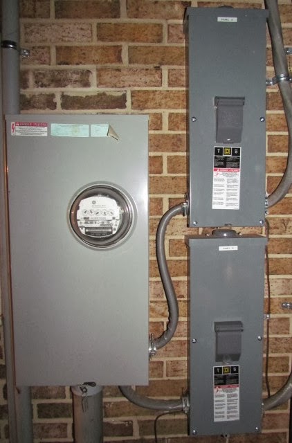
With my 400 amp service, the neutrals are bonded to a ground shared by the two 200 amp exterior disconnects, each of which power a separate 200 amp interior load center.

IMG_3582.JPG


I installed a TED 5002 to monitor my energy usage and confirmed that 15KW would suffice.

newey.jpg


I installed two Square D QOCGK2C interlock kits and two 50 amp double-pole breakers to occupy spaces 2 and 4 of each panel.

41Y-8pUQ9eL._AA160_.jpg
cd0410b5-e7e7-4c18-bcbe-d50d5f8b8df2_145.jpg
41Y-8pUQ9eL._AA160_.jpg
cd0410b5-e7e7-4c18-bcbe-d50d5f8b8df2_145.jpg


I used 
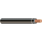
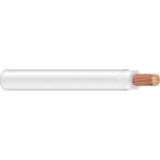
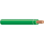
3/4 in. Flex Aluminum Conduit and 8 gauge THHN wire (rated for 50 amps and much easier to work with than Romex 6/3 with ground).

9269b8b9-81fb-47ca-990b-70bad966bbf5_145.jpg
0cd332ed-3a28-4e59-954d-18f30c9189a9_145.jpg
8a55d87c-148a-435e-845d-bd647629db60_145.jpg
85dd08f0-ddd5-42c2-bac3-236b7b9da9ca_145.jpg
2c80b84a-89a6-49e9-8b0b-c18bf0323b5e_145.jpg


I also used EMT to go through the wall.

7fbeb5e0-dfc9-4cfa-9c46-05370242e0f4_145.jpg
64ca02f4-9b81-491d-9ccd-5b60ee74e1da_145.jpg
d12f9936-5b81-4f7c-9e33-ad991a30cf7e_145.jpg
f48e4b3a-8493-4e5d-bb7d-37bfdaf8bb36_145.jpg


As discussed at length in this thread, a single inlet box would create a permanent parallel neutral path.


The secondary path would be sized for the generator and not for the utility so could be dangerous in the event of a primary neutral fault.


I opted to go with two inlet boxes as suggested earlier in this thread:

i thought of another more affordable option: you could install an interlock kit in each panel and give each panel its own inlet. Then you have the option of using two generators, or one generator with a Y cable. (you wouldnt want the Y cable connected when on utility power due to the bridging neutral situation)
The Y cable would not be installed unless the generator was connected and operating. With other proposed installations, the neutral connection would remain (both panels to where the generator connected) and this would be a permanent secondary neutral tie between the two panels, which you do not want.

And yes, the primary neutral is still connected, even with the Y cable, so in effect, the original primary neutral becomes the secondary neutral tie between panels when the genny is connected and up and running, but this is not so bad a situation as the original primary neutral is much heavier than the Y cable neutral.

A Coleman Cable 50 amp Y adapter routes power to two GE 50 Amp Twist Lock Power Inlets (larger and more robust than the popular Reliance Controls PB50).

cc-01920.jpg
2137ecc6-c38d-4ddf-9dc6-a26166b578d2_145.jpg


A Conntek 1450SS2-15 Temporary Power Cord with NEMA 14-50P Generator Plug to CS6364 Locking Connector is used to connect a 15KW PTO generator.

41-N5adeMiL._SL500_SS100_.jpg
image_11353.jpg


The PTO generator takes advantage of the 37hp diesel engine that we already maintain with regular use of our tractor, providing considerable power and confidence that it will work when needed, even if we haven't had an outage for years. We are also able to drive that "genset" to wherever we need electricity on our property or adjacent farms or even a neighbor's house if they have a more desperate need. There will be times during an outage when we may require use of the tractor for other things (plowing out, moving trees, etc.), but not anything that would take long enough to significantly impact comfort, spoil food, jeopardize livestock, etc.

Anyway, this approach worked for me. YMMV
 
Last edited:
To avoid these ads, REGISTER NOW!
Top Bottom