To avoid these ads, REGISTER NOW!

Jib crane, not normal install.

zkdiesel

Well-known member
Joined
Oct 6, 2013
Messages
8,292
Location
chicagoland cornfields
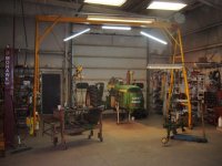
Gonna be custom making new shop from scratch and plans are for two jib cranes.
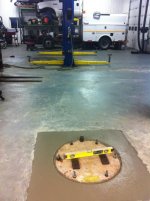
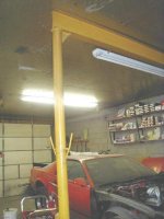
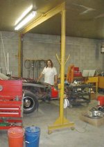
Did a while theead years ago about a retro jib crane install I did in my shop that’s a baseplate freestanding one. Busted out concrete, 4x4x4’ hole with rebar cage and anchors sticking out.


New ones, if I acquire the jib cranes before floor is poured, can I buy tubular steel that sleeve fits my jib crane od, and sink that 4 foot into my new floor with same rebar cage and massive cutout and have just a hollow tube sticking out of floor then? Drop crane in from top and then true and weld...... would save floor room without baseplates, only 12” tube sticking up
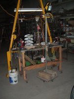
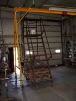
Cranes will be .5-1 Ton with 12’ ish reach

Would also allow me to buy shorter cranes and once I cut off bracing I could have floor stub sticking up extra to gain height....
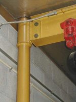
A foot of engagement with several plug weld locations down low and full bead at sleeve matchup would be more than adequate
 
To avoid these ads, REGISTER NOW!

driftpin

Well-known member
Joined
Dec 22, 2016
Messages
11,196
Location
Miami-Dade/Broward Co. Florida
A 4' X4' X4' pad would allow you to have a very long arm on that thing, and a much-higher lift capacity. Of course, that depends on the other specs of the jib crane too.

I suspect you're gonna want-to have the stationary immobile tube in-concrete machined for a tapered bearing at the bottom, and another at the top, but I'm no mechanical engineer. I'm assuming the drop-in post is going to be the pivoting part, or did I read it wrong and you intend the drop-in to be stationary (the welds)?
 
Last edited:
OP
Z

zkdiesel

Well-known member
Joined
Oct 6, 2013
Messages
8,292
Location
chicagoland cornfields
A 4' X4' X4' pad would allow you to have a very long arm on that thing, and a much-higher lift capacity. Of course, that depends on the other specs of the jib crane too.

I suspect you're gonna want-to have the stationary immobile tube in-concrete machined for a tapered bearing at the bottom, and another at the top, but I'm no mechanical engineer.

Only top would pivot. Taking exsisting jib crane and cutting off baseplate...

My exsisting crane. Would take crane similar to this and cut baseplate and stock round tube into inside diameter of tube that’s sunk in my 4x4x4 concrete square that’s cut deeper than exsisting floor would be
 

Attachments

  • F2E2E9AA-8BA3-4125-9C23-CC7CF0AE4FA5.jpg
    F2E2E9AA-8BA3-4125-9C23-CC7CF0AE4FA5.jpg
    154.2 KB · Views: 416
Last edited:

matt_i

Well-known member
Joined
Mar 14, 2008
Messages
10,725
Location
SE Michigan
It sounds like a huge pain to build in a way that can adjust-true and then weld. I can think of a set of jack bolts that are 90 degrees apart but keep in mind you are then talking about one weld bead at the top and 3-4 points of contact at the bottom.

What are existing dimensions? Around 12" OD column x 1/2" thick? It seems like it would be a big problem to source a 13" OD column thats 7/16" thick for example, to give you 1/8" of diametral clearance.

I would just stick with existing setup and not modify it. Is the 4' cube of concrete engineered for your setup or it seemed like enough overkill to prevent a problem?

I'm not quoting actual numbers but it seems like you'd be better off to be in the center of a 10' square (in the center of the saw cuts) that's poured 12" thick than a giant cube.

A few calcs, suppose your hole pattern is a 24" circle, 1" dia anchor bolts, 12" thick 'crete, You use epoxy with a 5ksi strength and a "working" strength of 2.5ksi (half). The circumference of the entire bolt is 1 * pi * 12 ~ 37 sq in * 2500 psi = 94000 lbs that fastener can support in tension, which is very likely stronger than the fastener itself (0.784 in^2 * 120ksi for B7 rods ~= 94ksi... and we should really use about 1/2 of that value) . Your 2000 lbs * 144 inches / 12 inch = 24000 lbs of uplift if its all on a single fastener which is well within the above.

Obviously your numbers would have to be put in, I'm not a P.E, etc. Just saying that the industrial installs (not the design) I've been part of don't have huge blocks sawn out of the floor, but the prep of the anchors is obvious
 
OP
Z

zkdiesel

Well-known member
Joined
Oct 6, 2013
Messages
8,292
Location
chicagoland cornfields
This was last time in an exsisting nice floor
J bolts with bits welded onto very ends to prevent pull out/straightening


Main reason I’m asking is it’s a cheap way to increase height of jibs. Lots of them at the 10’ mark, not many at the 14-15’ tall. So to extend a cheap one would require the same effort as installing them this way and gaining less above ground interfirance
 

Attachments

  • 13722ECB-E3E2-4FD6-A46A-B84F84B4E1C4.jpg
    13722ECB-E3E2-4FD6-A46A-B84F84B4E1C4.jpg
    90.8 KB · Views: 214
  • F85FCF9A-816B-4755-A494-E5BA0102C147.jpg
    F85FCF9A-816B-4755-A494-E5BA0102C147.jpg
    97.3 KB · Views: 225

Strouty

Well-known member
Joined
Mar 21, 2010
Messages
38,212
Location
Southern Maine
ZK, if building a new shop, why not make a bridge crane with two bridges? It could be incorporated into the building structure. You can usually find some pretty big bridge cranes for not too much money, then you could size it down to fit your needs. I think this would be a really nice option if you are looking at 14' or 15' tall.
 

sberry

Banned
Joined
Jun 18, 2005
Messages
35,747
Location
Brethren, Michigan
My pics are goofed up from here but just cause you had one design doesn't mean it needs to be the same. Lots of ways to do this, some easier and cheaper.
 
OP
Z

zkdiesel

Well-known member
Joined
Oct 6, 2013
Messages
8,292
Location
chicagoland cornfields
ZK, if building a new shop, why not make a bridge crane with two bridges? It could be incorporated into the building structure. You can usually find some pretty big bridge cranes for not too much money, then you could size it down to fit your needs. I think this would be a really nice option if you are looking at 14' or 15' tall.
Ideal but think would get very costly. Would have 75’ run of track, then getting electric to the hoist on a situation like that gets expensive in a hurry unless you run a 110 hoist and an extension cord on the ground

Think if I have 150’ of run, 20’ wise bean I’d have to have multiple support beams. Cost would probably be pretty good....
Where as a pair of jib cranes can be done for 2k
 

matt_i

Well-known member
Joined
Mar 14, 2008
Messages
10,725
Location
SE Michigan
I'd look into what it would take to fabricate a new, taller, larger diameter column as one piece and adapt your arm to that. If you are dead set on cutting, I'd cut it up high. The stresses are max in a cantilever at the fixed end, and go down from there. So if you are going to fabricate, put the joint in a low stress area.

I'm most familiar with the Gorbel design, its a big tube, has one solid metal post on the top of it to support the inner race of a tapered roller bearing. The outer race is in the top of the arm. They use what I term "X-678 turn rollers" to bear a couple feet down on the arm and roll around the OD of the big tube. The arm itself is all square tubing except for their rolled/formed unistrut-style track (of course bigger & heavier gage).

Bridge cranes are expensive. Even if you integrate it into a red iron building, the X-bracing for the building gets a lot more serious because of this side-load thats being put into the structure by the starting and stopping load. Columns are a must, have to buy the square-bar track (its like a railroad rail for large cranes) to match the wheels which have to have flanges. Bridge cranes sell at auctions but beware the 5 figure rigging fees to remove them with due-care. Everything has to be set level and track width adjusted within 1/8" or less. And you mentioned electrification...also consider the crane bay can't have any cords or pipes dropped from overhead, it all must come in from the sides....
 

kbs2244

Well-known member
Joined
Nov 11, 2006
Messages
14,065
Just remember that the pivot point on a jib crane is at the floor level of the vertical post.
The height of the vertical is not as important as the length of the arm.
Longer arms mean more stress for the same lifted weight.

I like a sub slab steel plate to provide a large footprint pushing down on the working side of the crane.
Down pressure is stronger than any pull pressure on the J bolts.
 
To avoid these ads, REGISTER NOW!
OP
Z

zkdiesel

Well-known member
Joined
Oct 6, 2013
Messages
8,292
Location
chicagoland cornfields
Just remember that the pivot point on a jib crane is at the floor level of the vertical post.
The height of the vertical is not as important as the length of the arm.
Longer arms mean more stress for the same lifted weight.

I like a sub slab steel plate to provide a large footprint pushing down on the working side of the crane.
Down pressure is stronger than any pull pressure on the J bolts.

Good idea. A circle welded onto my sink pipe below grade will prevent this
 

cbacres

Well-known member
Joined
May 28, 2010
Messages
5,998
Location
SW Florida
I like your plan on this, nice and clean floor area right by upright.

Another ahvantage is the floor slab can be tied into the footer.

You can run conduit to pole also for outlets, welders whatever.

Look forward to your new build.
 

sberry

Banned
Joined
Jun 18, 2005
Messages
35,747
Location
Brethren, Michigan
I will see if I can find some pics tomorrow. There are versions can hear on normal floor that don't need hi engineering and cost only a fraction.
 

sberry

Banned
Joined
Jun 18, 2005
Messages
35,747
Location
Brethren, Michigan
This is a simple one I did for a bud, depends on bay size. I was going to do one but kept and modified an A frame I already had and my building I big, at one time thought I might move it and did once for one job, been sitting within the same 5 ft for the last 25 years.
These were cheap, didn't require building mods, there is a slight difference compared to jib but I don't use it a lot. I got to have it when I need it but not in service every day. I have a heavy duty cherry picker which I actually use more. It replaced a forklift for a lot, most shop rigging jobs.
 

Attachments

  • a frame tool back.jpg
    a frame tool back.jpg
    92.1 KB · Views: 85
  • A frame paint.jpg
    A frame paint.jpg
    99 KB · Views: 96
  • motor crane 4.JPG
    motor crane 4.JPG
    22.2 KB · Views: 89
  • motor crane 2.JPG
    motor crane 2.JPG
    24.4 KB · Views: 88
  • motor crane 6.JPG
    motor crane 6.JPG
    32.6 KB · Views: 98
  • motor crane1.JPG
    motor crane1.JPG
    16.6 KB · Views: 94
  • tractor lights.jpg
    tractor lights.jpg
    147.8 KB · Views: 91
OP
Z

zkdiesel

Well-known member
Joined
Oct 6, 2013
Messages
8,292
Location
chicagoland cornfields
This is a simple one I did for a bud, depends on bay size. I was going to do one but kept and modified an A frame I already had and my building I big, at one time thought I might move it and did once for one job, been sitting within the same 5 ft for the last 25 years.
These were cheap, didn't require building mods, there is a slight difference compared to jib but I don't use it a lot. I got to have it when I need it but not in service every day. I have a heavy duty cherry picker which I actually use more. It replaced a forklift for a lot, most shop rigging jobs.

But it’s not near as handy and in the way a lot more than a pair of 14’ 360 jobs that can cover 56’ of shop distance..... makes it easy and handy to use for many things
Unloading trucks it commonly gets used for, skidsteer Work all the time, and the crane also services the loft in old and soon to be new building
 

sberry

Banned
Joined
Jun 18, 2005
Messages
35,747
Location
Brethren, Michigan
In the first it rolled out of the way against the wall. I will agree a 360 covers more ground but does leave a big pole out in the way in some cases, it could rotate 270 also and come from a corner too. There are other styles, I don't have pics. Jib also works good in building with heavy columns can often be made in to it.
The downside is they have to be very heavy to avoid deflection or droop, they may be costly. There are a couple guys on Miller have crane rails but they are in the biz, they fab heavy sections constantly. I am an occasional user, I can make do a little for occasional work. I can go a long time though between heavy lifts.
 

metlmunchr

Well-known member
Joined
Sep 10, 2011
Messages
1,278
The size crane you're considering is going to likely have a column made from 12" pipe (12.75" OD). Once you pass 12", pipe is sized by OD and wall. 14" x 1/2" wall is common, and would give you 1/8" clearance all around. Taking into account the fact that neither piece of pipe will be truly round, that's probably about as close a fit as you can safely assume will telescope together.

All that said, IMO sinking an oversize sleeve into your base and trying to get away without any flange and gussets at the floor level isn't a good idea. The concrete is going to shrink as it sets, and will pull back noticeably from the pipe. The only way to deal with this would be to put a removable oversize sleeve in the base, like a piece of Sonotube and then install the pipe sleeve after the base concrete is set, using epoxy non shrink grout. The grout would likely cost as much, if not more than, the 2.5 or so yards of concrete you put in the hole.

If you skip the grout, any clearance between the sleeve and the concrete wil cause the point loading against the concrete to go up exponentially. If the sleeve is dead tight, then you can assume the load is reacted by something approaching 180 degrees of the pipe. Any clearance, and the load is reacted by only whatever portion of the pipe is in contact with the concrete. This could easily be as little as 20 degrees, and would tend to get worse over time due to the loading over a small area.

Personally, I'd cut the column and add whatever length I wanted, leaving the base and gussets intact. Use the same pipe as was originally used in constructing the column. Bevel the ends for a standard **** weld and weld it out with 6010 or 7018.

To avoid making a bunch of welds in a ditch, I've welded as much as 120 ft of 6" sch 40 pipe together and set it in a ditch with a crane using a couple long wire rope slings spaced about 10 ft apart. The bending moment on the weld at the center of that length is about 36,000 ft-lbs. Looks like a rainbow when you lift it but never had any problems with the welds.

If you have 2000 lbs at the end of your 14 ft jib, that would give you a moment of 28,000 ft lbs reacted by the column. Add another 5000 ft lbs for the weight of the beam to be generous, and the moment is 33,000 ft lbs. That's a smaller moment than I have had on 6" pipe. As long as your welds are good, the load is nothing to worry about.

I realize it would be desirable to get rid of the flange and ring of bolts at the floor level, and it can be done. But, to do it right would likely cost you 4x to 5x as much as the cost of extending the column.
 

BD1

Well-known member
Joined
Mar 18, 2007
Messages
4,602
Location
north side
Check with manufactures on what they recommend for their products. Theirs are proven and tested .
 
To avoid these ads, REGISTER NOW!
Top Bottom